Hello everyone, I'm happy to share with you the teardown for Milfra TB-23 wall socket.
It is a 3 gang wall socket and following there are the photos of the box.
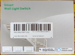
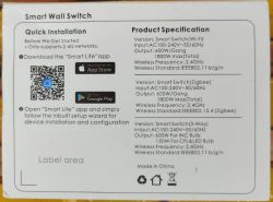
The product looks like this. Don't mind about the dimensions since it is available in different sizes
![[BK7231N] Disassembling Milfra TB-23 Wall Socket: A Detailed Guide [BK7231N] Disassembling Milfra TB-23 Wall Socket: A Detailed Guide](https://obrazki.elektroda.pl/1752500000_1713616453_thumb.jpg)
![[BK7231N] Disassembling Milfra TB-23 Wall Socket: A Detailed Guide [BK7231N] Disassembling Milfra TB-23 Wall Socket: A Detailed Guide](https://obrazki.elektroda.pl/9156598000_1713616453_thumb.jpg)
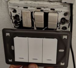
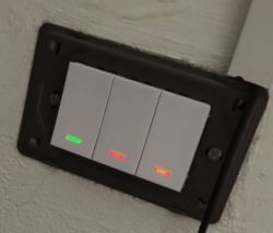
Teardown
To disassemble the socket it is necessary to remove the metal plate by pressing on the small stops highlighted in the picture.
Note that you need to remove them on both sides.
WARNING!: In the picture you can see two wires attached to the socket. Do NOT connect the socket to the power supply for any reason while you are disassembling it! the wire you see in the picture are NOT connected to the main and you don't neet to attach any wire at all in this phase. Unfortunately I did these photos only once I finished because I didn't know I would write the teardown yet, and that wires are connected because I was testing the socket.
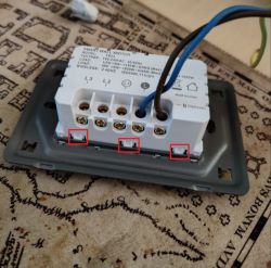
After removing it, there are others similar stops in the edge, which support the front buttons. Unfortunately I do not have these photos.
Once the frontal button are removed we will see this PCB board
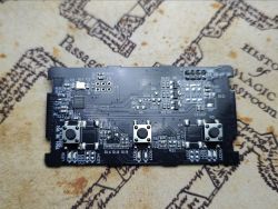
It is connected to another PCB board by the J1 jumper in the top right corner, but we don't need it. Everything we need is the PCB board showed in the photo.
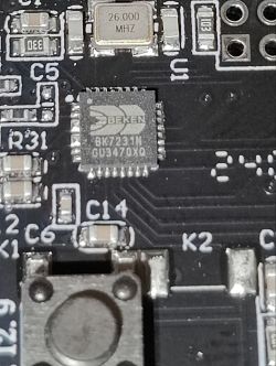
My device mounts a BK7231N chip, check your version by zooming on the chip with the camera of your phone for a better view.
Thanks to this post and with the help of a tester I was able to find the holes on the PCB that match to the RX, TX, CEN and 3v pins, while for GND and 5V pins I used those reported on the PCB.
These are the pins
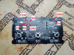
I used only TX and RX, while for power supply I used GND and 5V in the top right corner.
I do not tested the 3V pin and I suppose it is 3V because should be directly connected to the chip. If you do not want to take risks use 5V in the top right corner you too
The connection should look like this
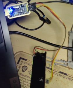
I'm sorry for the bad quality of the photo but I get it from a video I made for a friend. I didn't know I would write this guide yet.
Now you can solder the wires to the board, connect the programmer and flash OpenBeken!
I had some errors while flashing the firmware but then I noticed that I was writing with a too high baud rate, I decreased it to 115200 and it worked.
OpenBeken configuration
This is the configuration I found.
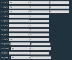
All the leds are working as expected: green light when off and red light when on. I didn't tried to change the colors so I do not know if it is possible.
HomeAssistant automatically recognized the device by mqtt.
I hope you would find this teardown helpful!
It is a 3 gang wall socket and following there are the photos of the box.


The product looks like this. Don't mind about the dimensions since it is available in different sizes
![[BK7231N] Disassembling Milfra TB-23 Wall Socket: A Detailed Guide [BK7231N] Disassembling Milfra TB-23 Wall Socket: A Detailed Guide](https://obrazki.elektroda.pl/1752500000_1713616453_thumb.jpg)
![[BK7231N] Disassembling Milfra TB-23 Wall Socket: A Detailed Guide [BK7231N] Disassembling Milfra TB-23 Wall Socket: A Detailed Guide](https://obrazki.elektroda.pl/9156598000_1713616453_thumb.jpg)


Teardown
To disassemble the socket it is necessary to remove the metal plate by pressing on the small stops highlighted in the picture.
Note that you need to remove them on both sides.
WARNING!: In the picture you can see two wires attached to the socket. Do NOT connect the socket to the power supply for any reason while you are disassembling it! the wire you see in the picture are NOT connected to the main and you don't neet to attach any wire at all in this phase. Unfortunately I did these photos only once I finished because I didn't know I would write the teardown yet, and that wires are connected because I was testing the socket.

After removing it, there are others similar stops in the edge, which support the front buttons. Unfortunately I do not have these photos.
Once the frontal button are removed we will see this PCB board

It is connected to another PCB board by the J1 jumper in the top right corner, but we don't need it. Everything we need is the PCB board showed in the photo.
My device mounts a BK7231N chip, check your version by zooming on the chip with the camera of your phone for a better view.

Thanks to this post and with the help of a tester I was able to find the holes on the PCB that match to the RX, TX, CEN and 3v pins, while for GND and 5V pins I used those reported on the PCB.
These are the pins

I used only TX and RX, while for power supply I used GND and 5V in the top right corner.
I do not tested the 3V pin and I suppose it is 3V because should be directly connected to the chip. If you do not want to take risks use 5V in the top right corner you too
The connection should look like this

I'm sorry for the bad quality of the photo but I get it from a video I made for a friend. I didn't know I would write this guide yet.
Now you can solder the wires to the board, connect the programmer and flash OpenBeken!
I had some errors while flashing the firmware but then I noticed that I was writing with a too high baud rate, I decreased it to 115200 and it worked.
OpenBeken configuration
This is the configuration I found.
Code: JSON

All the leds are working as expected: green light when off and red light when on. I didn't tried to change the colors so I do not know if it is possible.
HomeAssistant automatically recognized the device by mqtt.
I hope you would find this teardown helpful!


