logo elektroda
logo elektroda
X
logo elektroda

LampSmart Pro compatible LED light: communication with TMALLGENIE chip or how to addr. LED directly?

socrates324 2907 6
ADVERTISEMENT
  • #1 21120534
    socrates324
    Level 2  
    Hi @ all,

    so I bought this LED "smart" ceiling light.

    It works with what seems to be a proprietary 2.4 GHz remote and a Chinese App called "LampSmart Pro".

    I stumbled across this HomeAssistant post  and was hoping that I could use that. Unfortunately the lamp does not pair.

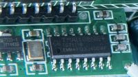
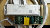
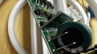
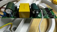
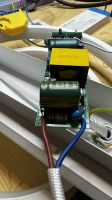
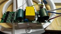
    I opened up the LED driver and found what seems to be the "communication board" (where the antenna wire is connected to) which uses a TMALLGENIE TG7111B (EMM4912324DDWF) chip.
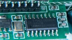
    Close-up of a communication board with a TMALLGENIE TG7111B chip.

    Now I would like to integrate the lamp into my Home Automation. As the ESP32 integration linked above does not work I'm trying to figure out alternative routes.

    I asked on the Home Assistant Forum where I was encouraged to post my question here.

    Possible routes to take that come to my mind:

    - reverse engineer (replay?) the commands sent by the proprietary 2.4 GHz remote
    - replace the communication daughter board with e.g. ESP32

    - replace the LED driver with a Shelly. This way my latest attempt, using a Shelly RGBW2. I can successfully turn on the LED lights, but only in "cold white", i.e. I cannot change the color temperature. Oddly enough, the LED driver that the lamp was shipped with only has two output wires (white and black). I wonder how they manage to change the color temperature?

    Anyway, any insights on how to process are very welcome as this is my first endeavor of this kind :)

    have a nice weekend!
  • ADVERTISEMENT
  • #2 21120661
    p.kaczmarek2
    Moderator Smart Home
    Welcome to forum, can you provide any more details on the device?
    It's not Tuya, so we can't hope for TuyaMCU?
    Are you saying that there is a separate WiFI module inside and separate MCU?
    How are they connected, do they use UART port for communication?
    Is the RF circuit connected directly to WIFI module, or to the MCU?

    We can try to figure out something for you, but we really need more information first. Maybe also a basic draft of connections could help.

    Added after 6 [minutes]:

    socrates324 wrote:

    - replace the LED driver with a Shelly. This way my latest attempt, using a Shelly RGBW2. I can successfully turn on the LED lights, but only in "cold white", i.e. I cannot change the color temperature. Oddly enough, the LED driver that the lamp was shipped with only has two output wires (white and black). I wonder how they manage to change the color temperature?

    There are three types of possible CW controls that I have encountered so far:
    - two PWM - one controls cool LEDs, second warm LEDs (classic control)
    - "alternate CW control" - two PWMs - but first controls temperature, second brightness
    - "I2C-like" protocol for chips like SM2135, BP5758, they are often used for full RGBCW
    EDIT: Option 4 is a WS2812B-like protocol. That requires 3 wires, power, ground, and data.

    Again, I am not yet able to to fully visualise how your lamp works, so any more photos/information will be very helpful


    EDIT2: If the communication board has only this SOIC chip, no WiFI module then maybe the simplest way would be replacing it with ESP, we can also try that. But if the communication board has only this SOIC chip, then how does this lamp talks to mobile App via WiFi? But there is no WiFI mention in the description... that could mean it indeed has no WiFI but maybe a Bluetooth instead? So the question then would be how to connect a Bluetooth lamp to HA....
    Helpful post? Buy me a coffee.
  • ADVERTISEMENT
  • #3 21120986
    socrates324
    Level 2  
    Thanks for having me :-)

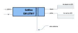
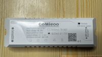
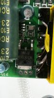
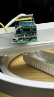
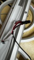
    As far as I can tell it is not Tuya but some proprietary stuff. As far as a drawing is concerned: at this point I have little information myself but I'll share what I hope is helpful. If there is any specific thing you'd like me to try - just ask. Connection diagram of GoMioo GM-LXTM-F with wire antenna and LED connections But I've made additional photos covering what I hope will / might be relevant:

    EDIT: the guy who implemented the ESP32 Home Assistant integration found out that the App communicates via BLE. And Bluetooth Low Energy would be rather difficult to reverse-engineer as I was told in the Home Assistant thread.
  • ADVERTISEMENT
  • #4 21121257
    p.kaczmarek2
    Moderator Smart Home
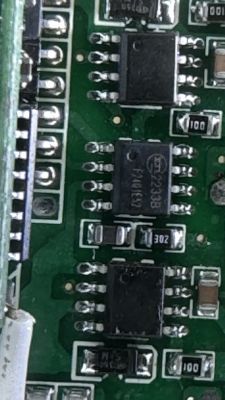
    So that's not even WiFi.. okay ,the simplest way would be to investigate this part:
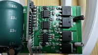
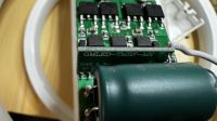
    Close-up of a printed circuit board with various electronic components in SOIC packages.
    Are those MOSFETs? Or LED drivers? How are they connected?
    And then try to replace RF section with ESP8266 or similiar WiFi module.

    Which pins of RF chip (SOIC case) are connected to those MOSFETs/LED drivers?
    Helpful post? Buy me a coffee.
  • ADVERTISEMENT
  • #5 21122403
    socrates324
    Level 2  
    >>21121257
    just a small update: I didn't manage to investigate this yesterday and I'm currently on business travel so I won't have a chance to look at it again until coming weekend.
  • Helpful post
    #6 21122406
    p.kaczmarek2
    Moderator Smart Home
    Ok, we can wait. We will try to do "brain transplant" to ESP once you're ready. It should be very easy, as the RF module also seem to be running on on 3.3V.
    Helpful post? Buy me a coffee.
  • #7 21127944
    socrates324
    Level 2  
    So I tried to get to the bottom of this and found a few "obstacles"...

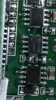
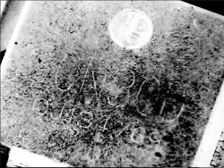
    1. The manufacturer seems to have tried to scrape off the labeling on the IC's. On two of the three ICs in a row it is totally gone, the other one is barely readable. I used a USB microscope hoping to get better results.
     Close-up of a circuit chip with partially scraped-off markings.The big ones seem to be "30N30D" but I couldn't find any datasheets online.

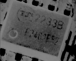
    Close-up of an integrated circuit with barely visible 2233B marking.The small ones read 2233B, again I wasn't able to find any datasheets.

    2. I currently lack the equipment to really "ping" the circuit. I have a multimeter at hand but the tip is too large to be sure where I connect and verify continuity.

    3. The lamp really smells bad as if it is full of chemicals that get into the air. Not something I will install in my living room soon.

    4. I found this Github repository lampify which provides a small CLI application to pair via BLE to the lamp and send commands. It's not perfect and it requires a Raspberry PI but it seems to work. In a perfect world I would be able to port this code to ESP32, but as I'm lacking any C knowledge, this is out of scope for me.

    5. I will now put the lamp into the garage in order to get rid of the smell. And I will try to tinker a python script to be able to control the lamp via MQTT making use of the "lampify" binary.


    I would have loved to embark on this endeavor of replacing the brain of the lamp because I'm sure I could have learned a lot. And I very much appreciate your support and would like to thank you again.

    But for now I will put the "lamp project" away until all the chemicals have subsided. 

    Have a nice weekend!
Topic summary

The discussion revolves around integrating a proprietary LED ceiling light, which operates via a 2.4 GHz remote and the LampSmart Pro app, into a home automation system. The user discovered that the lamp uses a TMALLGENIE TG7111B chip for communication. Initial attempts to pair the lamp with Home Assistant were unsuccessful, leading to suggestions for alternative approaches, including reverse engineering the remote commands or replacing the communication board with an ESP32 or ESP8266 module. The user provided images of the internal components, including MOSFETs and LED drivers, but faced challenges due to obscured IC labeling and a lack of testing equipment. A GitHub repository named "lampify" was mentioned as a potential resource for BLE pairing.
Summary generated by the language model.
ADVERTISEMENT