Teardown of Litemate LM044: SmartHome WiFi LED Lamp 9W B22 BK7231N (CBLC5) with BP5758 driver
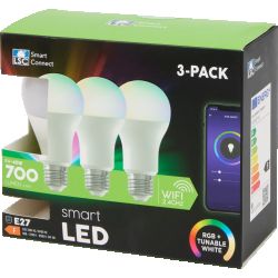
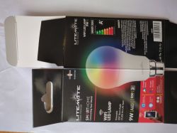
Packaging:
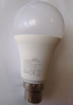
Bulb with markings:
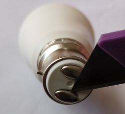
Prise out the press fitted electrical contacts:
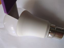
Loosen silicone sealant before twisting the plastic bulb cover back and forth to free it:
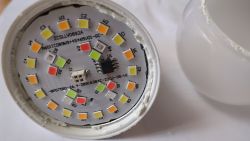
First sight of the BP5758 driver and four pin connector surrounded by Red, Green and Blue LEDs as well as Cool and Warm white LEDs:
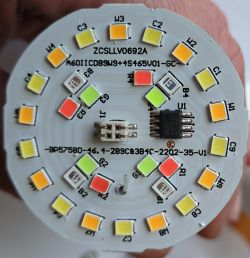
Close up of driver, and LEDs:
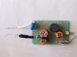
Board CX2228 with daughter-board CBLC5:
Bottom of board showing traces and SMDs:
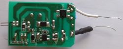
Back of daughter-board CBLC5 :
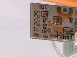
Front of daughter-board CBLC5 with BT7321N behind sticker:
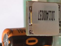
Front of daughter-board CBLC5 with sticker removed to show BT7321N:
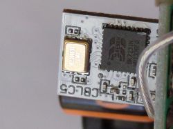
Tracing data and clock pins
J4 - P4 on BP5758 SCL
J3 - P3 on BP5758 SDA
J2 -
J1 - P2 on BP5758 High Voltage Input
J4 - CBLC5 PWM0 P6
J3 - CBLC5 PWM4 P24
Ergo:
BP5758 S-Clock =PWM0 (P6)
BP5758 S-Data = PWM4 (P24)
Mapping order:
Red: 1
Green: 0
Blue: 2
Cool: 4
Warm: 3
Pin-out References:
https://github.com/dbuezas/esphome-bp5758/blob/main/BP5758D_EN_DS_Rev.1.1.pdf
https://docs.libretiny.eu/boards/cblc5/#pinout
AI: Did you encounter any issues or have specific questions about the components or functionality during the teardown?
Order of LEDs was off but specifying a mapping order sorted that out.
Packaging:

Bulb with markings:

Prise out the press fitted electrical contacts:

Loosen silicone sealant before twisting the plastic bulb cover back and forth to free it:

First sight of the BP5758 driver and four pin connector surrounded by Red, Green and Blue LEDs as well as Cool and Warm white LEDs:

Close up of driver, and LEDs:

Board CX2228 with daughter-board CBLC5:

Bottom of board showing traces and SMDs:

Back of daughter-board CBLC5 :

Front of daughter-board CBLC5 with BT7321N behind sticker:

Front of daughter-board CBLC5 with sticker removed to show BT7321N:

Tracing data and clock pins
J4 - P4 on BP5758 SCL
J3 - P3 on BP5758 SDA
J2 -
J1 - P2 on BP5758 High Voltage Input
J4 - CBLC5 PWM0 P6
J3 - CBLC5 PWM4 P24
Ergo:
BP5758 S-Clock =PWM0 (P6)
BP5758 S-Data = PWM4 (P24)
Mapping order:
Red: 1
Green: 0
Blue: 2
Cool: 4
Warm: 3
Pin-out References:
https://github.com/dbuezas/esphome-bp5758/blob/main/BP5758D_EN_DS_Rev.1.1.pdf
https://docs.libretiny.eu/boards/cblc5/#pinout
AI: Did you encounter any issues or have specific questions about the components or functionality during the teardown?
Order of LEDs was off but specifying a mapping order sorted that out.


