This device was a challenging one to get working perfectly, but with some fantastic support from p.kaczmarek2 and a few firmware revisions we got it working perfectly. The following is a teardown and programming of the device as well as the required Home Assistant integration. It is available in Australia from Kmart. However there are many of what appear to be the exact same model available under a number of different brandings online.
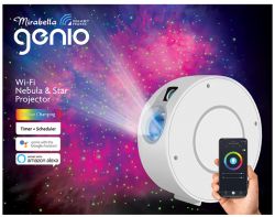
Genio Galaxy Lamp
This device differs from most normal ESP devices. It has 3 main componenets, and RGB led/driver, laser and a motor.
The basic operation is that the RGB led is projected through a calleidoscope like lense, which is then projected through a fresnel style glass plate and finally out of the unit through a magnification lense. What this achieves is a coloured cloud like image, akin to that of a nebula or galaxy. The laser, which looks to be fairly high power also projects through its on caleleidoscope style tube which then is projected through a diffusion lense and out of the unit. This creates the stars of the "galaxy". Where it gets interesting is that both the fresnel lense and calleidoscope tube for the laser have a gear attached to them. These gears mesh with each other and are geared down to be driven by the motor. This achieves an opposite rotation of the laser and RGB led, i.e. the stars spin clockwise and the LED counter-clockwise!
It makes for a fantastic effect on the ceiling of any room.


Interior
After removing 4 screws from the outside of the housing, the device can be slpit in half. There is a cable between the Button board and the main PCB.
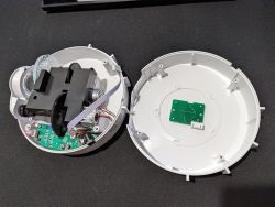
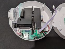
Remove 3 screws from the PCB to access programing headers.
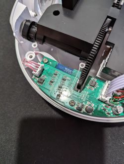
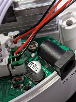
3rd screw hidden behind motor and laser connectors.
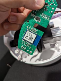
WB3s Chip (BK7231T)
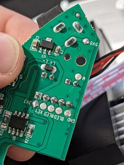
TX and RX Pins for programing. (Bottom of PCB)
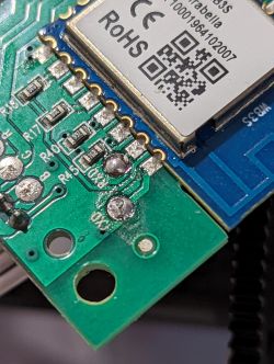
3v3 and GND pins for Programing. (Bottom of PCB)
Programming of the BK7321T
Programming BK7231T
Download the last batch binaries and BKwriter 1.60 from:
Link
All operations are performed after disconnecting the product from the electrical network.
Depending on your programmer, connect 3v3, GND RX and TX to their corresponding headers on the PCB. Examples of this can be seen in many other forum posts. Unfortunately I did not take any photos at the time.
Programming
Connect the USB UART converter, you may need to connect to the 5v pad depending on your programmer as some don't produce enough current to correctly start the Wifi module.
Run BKwriter 1.60. (Link)
Make a copy of the original batch (Read button), programming is done in the same way, we just first choose what batch we want to upload.
Choose what batch to upload (here, select the UA versions) and start programming (waiting for BK booting):
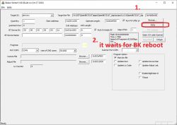
Now, as long as BKwriter is actively waiting for the BK boot signal, temporarily connect CEN to ground (here it is just on the USB dongle pin), literally for a second. Only then will the actual programming begin:
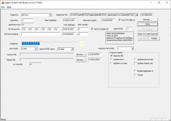
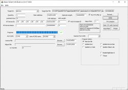
Programming Success:
The BK access point is already visible:
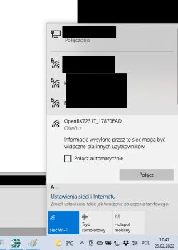
Connect to the WiFi point created by the BK7231T.
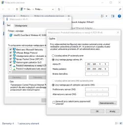
Here you may need to set our WiFi to a rigid IP, e.g. 192.168.4.10, in case DHCP does not work:
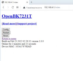
Open the page 192.168.4.1:
In Config, set your wifi credentials (e.g. information on our home WiFi):
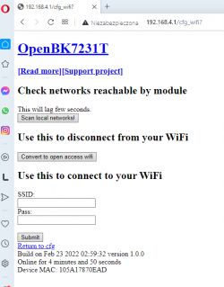
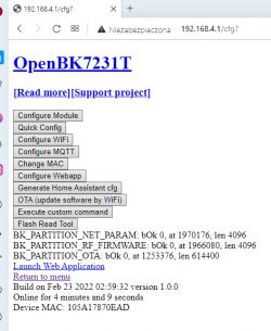
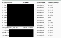
After connecting to your WiFi, reset the system. You may also need to disconnect the power supply temporarily or wait a minute for the device to join our network. Its new IP can be found on our router in the list of DHCP clients:
Pin Configuration
Once connected to the device. Click "Config" and then "Configure Module"
Your settings should be as follows. This may vary from device to device and depending on brand so you may have to experiment.
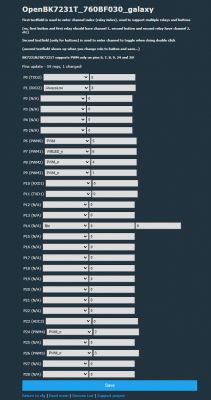
Click Save.
Next click "Configure General" It should be set like the following:
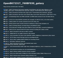
Thank you to p.kaczmarek2 for adding a few custom flags and settings to the firmware to get this working perfectly!
Click Save.
Finally we need to run a script on the device to enable proper control in Home Assistant.
On the home screen of the device click "Launch Web Application"
Go to the "Filesystem" tab
Click the "Create File" button
Create a file called "autoexec.bat"
In the editing box paste the following script:
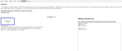
Click "Save, Reset SVM and Run the file as script thread"
Restart the device.
This script enables the PWM toggler.
PWM toggler provides you an abstraction layer over PWM channels
and allows you to enable/disable them without losing the set PWM value. The script also adds the ability to have RGB, laser and motor toggle via only toggling the RGB control. Bassically it tells the controller "if LEDState changes to 0, do a enable/disable on toggler."
You can choose to comment this part of the script out if you would prefer not to have it activated. To enable it at a later time just edit the scipt via the web application and un-comment the "addEventHandler" sections.
PWM toggler was created to support this lamp with RGB LED and PWM laser and PWM motor. This allows Home assistant to recognise the device as 3 light entities, giving full control over each aspect of the device whilst remebering the values they are set at.
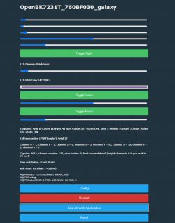
Your new home screen should look like the following:
Home Assistant Integration
Providing you have MQTT correctly set-up in Home Assistant, copy the following into your MQTT devices section of your configuration:
The Unique ID will be specific to your device and you will need to replace the example code with your device ID. This can be found on the Home Assistant Configuration page of the device. Only copy the Unique ID from the Home Assistant Configuration Page. The rest of the example configuration will not work in Home Assistant:
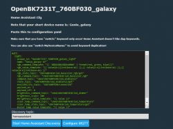
Adjust the unique ID to suit each part of the device e.g. OpenBK7231T_760BF030_galaxy_light, OpenBK7231T_760BF030_galaxy_laser and OpenBK7231T_760BF030_galaxy_motor. 3 of the same Unique IDs will not work and Home Assistant will only detect 1 entity.
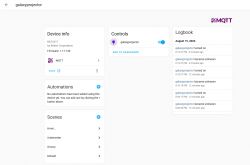
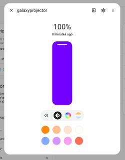
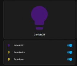
Once you have restarted Home Assistant you should have 3 entities named light.GenioRGB, light.GenioLaser and light.GenioMotor. Keep in mind changing the name of these entities in your configuration willl change the name that they are displayed with.

Operation
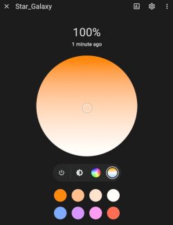
You should be able to select any RGB colour from the colour wheel, turn on the laser to any brightness and adjust the motor to any speed. Something to note is that the Laser and Motor are electrically connected within the device. This means that setting the laser to maximum brightness with the motor off will result in a dim laser output. Activating the motor immediately increases the laser brightness. The motor can spin extremely slow and this will still allow full brightness of the laser. I assume this is an effort to prevent the laser from damaging the internals of the device and outputing a static beam. Finally the button on the side of the device has been set as a master ON/OFF button for the lamp. It should retain all brightness values when toggled. You can change the function of this button by changing the assignment of the button channel on the module configuration page.
Your device should be fully operational now!
Again a huge thanks to p.kaczmarek2 for the firmware and for the modifications to get this device working flawlessly!

Genio Galaxy Lamp
This device differs from most normal ESP devices. It has 3 main componenets, and RGB led/driver, laser and a motor.
The basic operation is that the RGB led is projected through a calleidoscope like lense, which is then projected through a fresnel style glass plate and finally out of the unit through a magnification lense. What this achieves is a coloured cloud like image, akin to that of a nebula or galaxy. The laser, which looks to be fairly high power also projects through its on caleleidoscope style tube which then is projected through a diffusion lense and out of the unit. This creates the stars of the "galaxy". Where it gets interesting is that both the fresnel lense and calleidoscope tube for the laser have a gear attached to them. These gears mesh with each other and are geared down to be driven by the motor. This achieves an opposite rotation of the laser and RGB led, i.e. the stars spin clockwise and the LED counter-clockwise!
It makes for a fantastic effect on the ceiling of any room.


Interior
After removing 4 screws from the outside of the housing, the device can be slpit in half. There is a cable between the Button board and the main PCB.


Remove 3 screws from the PCB to access programing headers.

3rd screw hidden behind motor and laser connectors.

WB3s Chip (BK7231T)

TX and RX Pins for programing. (Bottom of PCB)

3v3 and GND pins for Programing. (Bottom of PCB)

Programming of the BK7321T
Programming BK7231T
Download the last batch binaries and BKwriter 1.60 from:
Link
All operations are performed after disconnecting the product from the electrical network.
Depending on your programmer, connect 3v3, GND RX and TX to their corresponding headers on the PCB. Examples of this can be seen in many other forum posts. Unfortunately I did not take any photos at the time.
Programming
Connect the USB UART converter, you may need to connect to the 5v pad depending on your programmer as some don't produce enough current to correctly start the Wifi module.
Run BKwriter 1.60. (Link)
Make a copy of the original batch (Read button), programming is done in the same way, we just first choose what batch we want to upload.
Choose what batch to upload (here, select the UA versions) and start programming (waiting for BK booting):

Now, as long as BKwriter is actively waiting for the BK boot signal, temporarily connect CEN to ground (here it is just on the USB dongle pin), literally for a second. Only then will the actual programming begin:

Programming Success:

The BK access point is already visible:

Connect to the WiFi point created by the BK7231T.
Here you may need to set our WiFi to a rigid IP, e.g. 192.168.4.10, in case DHCP does not work:

Open the page 192.168.4.1:

In Config, set your wifi credentials (e.g. information on our home WiFi):


After connecting to your WiFi, reset the system. You may also need to disconnect the power supply temporarily or wait a minute for the device to join our network. Its new IP can be found on our router in the list of DHCP clients:

Pin Configuration
Once connected to the device. Click "Config" and then "Configure Module"
Your settings should be as follows. This may vary from device to device and depending on brand so you may have to experiment.

Click Save.
Next click "Configure General" It should be set like the following:

Thank you to p.kaczmarek2 for adding a few custom flags and settings to the firmware to get this working perfectly!
Click Save.
Finally we need to run a script on the device to enable proper control in Home Assistant.
On the home screen of the device click "Launch Web Application"
Go to the "Filesystem" tab
Click the "Create File" button
Create a file called "autoexec.bat"
In the editing box paste the following script:
startDriver PWMToggler
toggler_channel0 4
toggler_name0 Laser

toggler_channel1 5
toggler_name1 Motor


// this will make disabling LED also disable both togglers (laser and motor)
addEventHandler LEDState 0 backlog toggler_enable0 0; toggler_enable1 0;
// this will make enabling LED also enable both togglers (laser and motor)
// Comment out if you don't want it!
addEventHandler LEDState 1 backlog toggler_enable0 1; toggler_enable1 1;

Click "Save, Reset SVM and Run the file as script thread"
Restart the device.
This script enables the PWM toggler.
PWM toggler provides you an abstraction layer over PWM channels
and allows you to enable/disable them without losing the set PWM value. The script also adds the ability to have RGB, laser and motor toggle via only toggling the RGB control. Bassically it tells the controller "if LEDState changes to 0, do a enable/disable on toggler."
You can choose to comment this part of the script out if you would prefer not to have it activated. To enable it at a later time just edit the scipt via the web application and un-comment the "addEventHandler" sections.
PWM toggler was created to support this lamp with RGB LED and PWM laser and PWM motor. This allows Home assistant to recognise the device as 3 light entities, giving full control over each aspect of the device whilst remebering the values they are set at.
Your new home screen should look like the following:

Home Assistant Integration
Providing you have MQTT correctly set-up in Home Assistant, copy the following into your MQTT devices section of your configuration:
  light:
    - unique_id: "OpenBK7231T_760BF030_galaxy_light"
      name: "GenioRGB"
      rgb_command_template: "{{ '%02x%02x%02x' | format(red, green, blue)}}"
      rgb_state_topic: "obk760BF030/led_basecolor_rgb/get"
      rgb_command_topic: "cmnd/obk760BF030/led_basecolor_rgb"
      rgb_value_template: "{{ value[0:2]|int(base=16) }},{{ value[2:4]|int(base=16) }},{{ value[4:6]|int(base=16) }}"
      #rgb_value_template: "{{ '%02x%02x%02x'| format(red, green, blue) }}"
      command_topic: "cmnd/obk760BF030/led_enableAll"
      state_topic: "obk760BF030/led_enableAll/get"
      availability_topic: "obk760BF030/connected"
      payload_on: 1
      payload_off: 0
      brightness_command_topic: "cmnd/obk760BF030/led_dimmer"
      brightness_scale: 100
      brightness_state_topic: "obk760BF030/led_dimmer/get"
      brightness_value_template: "{{value}}"

    - unique_id: "OpenBK7231T_760BF030_galaxy_laser"
      name: "GenioLaser"
      command_topic: "cmnd/obk760BF030/toggler_enable0"
      state_topic: "obk760BF030/toggler_enable0/get"
      payload_on: 1
      payload_off: 0
      brightness_command_topic: "cmnd/obk760BF030/toggler_set0"
      brightness_scale: 100
      brightness_state_topic: "obk760BF030/toggler_set0/get"
      brightness_value_template: "{{value}}"
      retain: true
      qos: 1

    - unique_id: "OpenBK7231T_760BF030_galaxy_motor"
      name: "GenioMotor"
      command_topic: "cmnd/obk760BF030/toggler_enable1"
      state_topic: "obk760BF030/toggler_enable1/get"
      payload_on: 1
      payload_off: 0
      brightness_command_topic: "cmnd/obk760BF030/toggler_set1"
      brightness_scale: 100
      brightness_state_topic: "obk760BF030/toggler_set1/get"
      brightness_value_template: "{{value}}"
      retain: true
      qos: 1
The Unique ID will be specific to your device and you will need to replace the example code with your device ID. This can be found on the Home Assistant Configuration page of the device. Only copy the Unique ID from the Home Assistant Configuration Page. The rest of the example configuration will not work in Home Assistant:

Adjust the unique ID to suit each part of the device e.g. OpenBK7231T_760BF030_galaxy_light, OpenBK7231T_760BF030_galaxy_laser and OpenBK7231T_760BF030_galaxy_motor. 3 of the same Unique IDs will not work and Home Assistant will only detect 1 entity.
Once you have restarted Home Assistant you should have 3 entities named light.GenioRGB, light.GenioLaser and light.GenioMotor. Keep in mind changing the name of these entities in your configuration willl change the name that they are displayed with.

Operation
You should be able to select any RGB colour from the colour wheel, turn on the laser to any brightness and adjust the motor to any speed. Something to note is that the Laser and Motor are electrically connected within the device. This means that setting the laser to maximum brightness with the motor off will result in a dim laser output. Activating the motor immediately increases the laser brightness. The motor can spin extremely slow and this will still allow full brightness of the laser. I assume this is an effort to prevent the laser from damaging the internals of the device and outputing a static beam. Finally the button on the side of the device has been set as a master ON/OFF button for the lamp. It should retain all brightness values when toggled. You can change the function of this button by changing the assignment of the button channel on the module configuration page.
Your device should be fully operational now!
Again a huge thanks to p.kaczmarek2 for the firmware and for the modifications to get this device working flawlessly!
Cool? Ranking DIY


