logo elektroda
logo elektroda
X
logo elektroda

Identifying SM-039 (BL602) Module in Woolley (Sonoff/Ewelink) SA-032 Smart Plug with BL0937

divadiow 1026 20
ADVERTISEMENT
  • Helpful post
    #1 21126246
    divadiow
    Level 35  
    Sometimes I look for user-posted pictures of IoT devices on Ali Express in the off-chance they've included an internal shot that reveals a module I do not have or one I've never seen before. This was the case for a South American smart plug - Woolley SA-032 - Ewelink/Sonoff/ITEAD origin device.

    https://vi.aliexpress.com/item/1005005782675033.html

    Advertisement for the Woolley SA-032 smart plug on AliExpress.

    I've scoured the internet for mention of the SM-039 inside, but there is nothing so far. It looks like it could be a Trolink SM-xx device, but they say their only BL602 modules are SDV-002 and SM-028. I've not heard back from Ewelink/Sonoff yet.

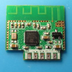
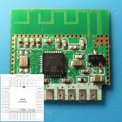
    This is the SM-039 and I attach a dump taken from BLDevCube 1.8.9
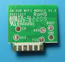
    SM-039 WiFi module with PCB markings. IoT module with visible electronic components and a BL602 chip on a blue background.

    uart boot:

    Code: Text
    Log in, to see the code


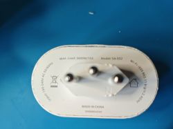
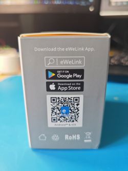
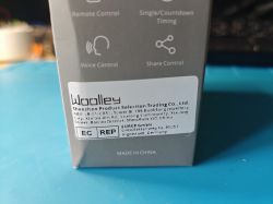
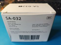
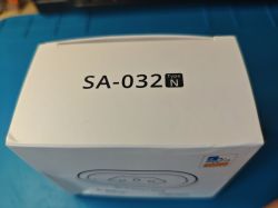
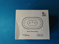
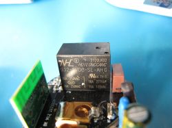
    The module in-situ and the device/packaging:
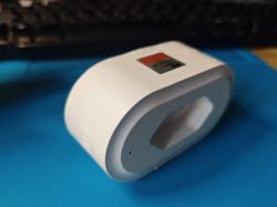
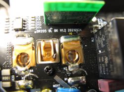
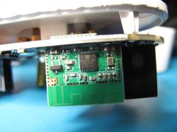
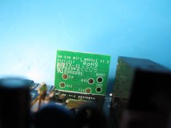
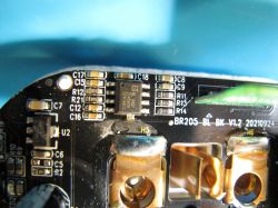
    White smart plug lying on a blue surface. Photo of the underside of a smart plug model SA-032 with visible technical specifications. Smart plug packaging with QR code to download eWeLink app. Photo of Woolley SA-032 smart plug packaging with manufacturer information. White packaging of the SA-032 smart plug with specifications. Box with the label SA-032 Type N. Box of a Wi-Fi smart plug supporting Google and Alexa on a blue background. Close-up of a relay on the circuit board of an IoT device. Close-up of the interior of an IoT module with visible components and connectors. Close-up of the BL602 module inside an IoT device. SM-039 WiFi module with markings on a green circuit board. Close-up of an electronic circuit board with components labeled as BR205_BL_BK_V1.2.

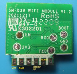
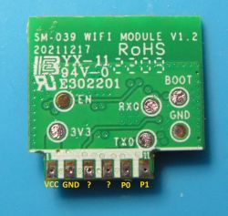
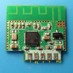
    The power monitoring chip is a standard BL0937. There are two LEDs but with OBK finder I can only light one, a blue one. The second LED does light when probed with a multimeter. I've done a lot of tracing but some of the module pads remain a mystery, not helped by resistors being in the way of paths, my lack of a decent magnifying glass and the width of the end of my multimeter probes.

    definitely a work in progress. Text is mostly scribbles about possibilities/unsureness.
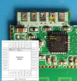
    BL602 module on PCB with pins and schematic
    SM-039 WiFi module with labeled connectors.

    The only 100% knowns are VCC and GND.

    The silk-screen number prints of 1, 11, 0 (or 9) and 12 (or 2) don't seem to correlate to where I am tracing them to on the BL602 chip.

    I have flashed with OBK and these are known:

    "0": "Btn",
    "1": "WifiLED", - Blue LED "LED1"
    "12": "Rel"

    I guess my question is, for the BL602 please confirm P# in OBK map to GPIO# on BL602

    eg OBK P0 = GPIO0 = Pin 1 of IC ?

    I ask because I'm just not seeing this map through when tracing with multimeter, though that could be because of the reasons given above.

    On a different note, here are some semi-interesting bits in the binary seen in HxD, though I'm unsure if they're general SDK mentions or actual config for this device

    cse7759 chip exist...cse7759b_uart_timer.cse7759bProcess.[%10u][%s: %s:%4d] cse7759b init OK (there's no mention of BL0937)

    A bunch of AT commands

    Code: Text
    Log in, to see the code


    mentions of the module, GPIOs, blinky LEDs and button presses

    Code: Text
    Log in, to see the code


    but maybe that's just from the SDK/dts https://github.com/bouffalolab/BLOpenFlasher/...device_tree/bl_factory_params_IoTKitA_40M.dts
  • ADVERTISEMENT
  • Helpful post
    #2 21127184
    p.kaczmarek2
    Moderator Smart Home
    I dont' see that shape of socket very often. It reminds me mostly of the old sockets, it's suprising to see it used now.

    The BL602 pin naming is very simple, you can see here:
    https://github.com/openshwprojects/OpenBK7231T_App/blob/main/src/hal/bl602/hal_pins_bl602.c
    There are no aliases, so internal pin numbers are used:
    Code: C / C++
    Log in, to see the code

    So that's how are pins manipulated:
    Code: C / C++
    Log in, to see the code

    It's simple as that on BL602. Still, keep in mind that it may be different for different platforms. On W800, for example, we have a lookup table to map artificial OBK pin numbers to W800/W600 ports and bits:
    https://github.com/openshwprojects/OpenBK7231T_App/blob/main/src/hal/w800/hal_pins_w800.c
    Helpful post? Buy me a coffee.
  • #3 21128204
    divadiow
    Level 35  
    Sonoff support have replied to say the datasheet contains proprietary information so they will not supply. At least that confirms it's theirs.

    I've asked them to supply what they can.
  • #4 21131462
    divadiow
    Level 35  
    on a slightly different note, it is curious how the factory firmware was fine booting on my external PSU (up to 5A available to connected devices) but with OBK it will boot loop unless it's plugged into the mains. Could there be something specific to OBK/old SDK that causes BL602 to be weird with power when running OBK?
  • ADVERTISEMENT
  • #5 21131465
    p.kaczmarek2
    Moderator Smart Home
    Measure current usage. They may have enabled powersave 1 by default. I could do it too, but I am not sure - I still remember those few strange reports about PowerSave breaking stuff. I know for certain that it breaks BL0937 and IR, but maybe there is more.
    Helpful post? Buy me a coffee.
  • #6 21131724
    divadiow
    Level 35  
    hmm. I don't really have a sensitive enough way to measure the module only. The XL4015 I'm using doesn't even register any current, which is unusual because it *does* register current for devices that draw less and do work fine.

    Anyway, this BL602 just reboots continuously at this point at uart output "Start Wi-Fi fw @99ms"

    I guess this is before powersave 1 can kick in, which is now set in startup command before I desoldered it again.

    Console display showing GPIO configuration errors and a romfs issue for BL602.

    Added after 55 [seconds]:

    I must have a load of AMS1117-3.3 I can make another ext PSU from to try.

    Added after 4 [minutes]:

    still doesn't make sense because the BL602 should be free to draw up to 1.5A (the cut-off I have set right now) from the XL4015

    Added after 34 [minutes]:

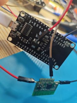
    forgot I had the lolin in my bits box. easy.

    Lolin module and green PCB board connected with wires on a blue mat.

    well it boots now. but has rebooted because of Reboot reason: BL_RST_POWER_OFF

    fine. now I get on with attaching LEDs to work out the GPIOs properly.
  • Helpful post
    #7 21131810
    miegapele
    Level 15  
    Flimsy wires is most likely the issue. I noticed the same while dealing with bl602. It looks sensible to voltage drops. And that's why it works fine powered from original source.
    You can make your wires better, or increase voltage to 3.6v and it should be fine
  • ADVERTISEMENT
  • #9 21131835
    p.kaczmarek2
    Moderator Smart Home
    maybe connecting 100nF capacitor between GND and VDD on the BL602 module itself can help it working while keeping wires long?
    Helpful post? Buy me a coffee.
  • #10 21132126
    divadiow
    Level 35  
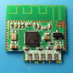
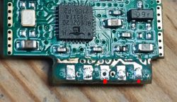
    interesting. no wonder I was getting confused/frustrated. there appears to be two P1s. yes, test LEDs on both light when toggling P1 high

    Screenshot of GPIO Doctor Pins interface with settings for P0 and P1.

    Close-up of an electronic module with visible components on a green circuit board. SM-039 WiFi module board with visible connector labels.


    The unknowns do not light an LED or even blip the multimeter toggling any of the 3 IO doctor buttons
  • #12 21132459
    divadiow
    Level 35  
    well, they do. I had traced the BL0937 CF, EL, CF1 and had made notes in pics above. There also appears to be two P12s. There's continuity between the yellow P12 label and the red dots right to the BL602 GPIO12 pin.

    Weird. Or is there a plausible explanation?

    Electronic board with an integrated circuit and pin labels P1 and P12.
  • #13 21132878
    p.kaczmarek2
    Moderator Smart Home
    This is very strange. Maybe you could peel of some of the soldermask to investigate the tracks futher. I'd rather expect to find a short somewhere, but you've posted full photos of board and I see nothing like that...
    Helpful post? Buy me a coffee.
  • #14 21132884
    divadiow
    Level 35  
    indeed. Im hoping two more devices with same module will arrive soon. If they do, I wouldn't mind destroying this one just to find out. It's entirely possible I've damaged it, though it does still work.

    I could do with an acid bath or something remove top layer of protection.

    Added after 1 [hours] 53 [minutes]:

    >>21132459

    they looked connected to me
    Close-up of a printed circuit board with an integrated circuit and other electronic components.
  • #15 21133100
    p.kaczmarek2
    Moderator Smart Home
    By the way, what is that 09 part doing? Is this a transistor? How is it connected?
    Helpful post? Buy me a coffee.
  • ADVERTISEMENT
  • #18 21133148
    divadiow
    Level 35  
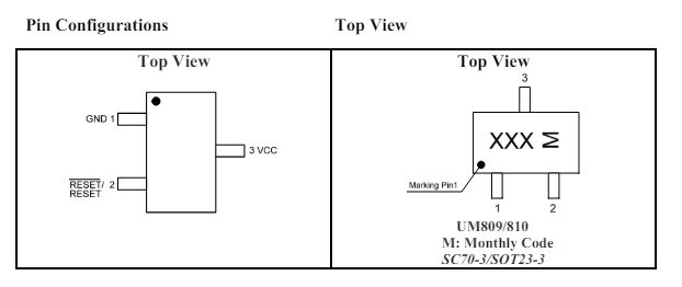
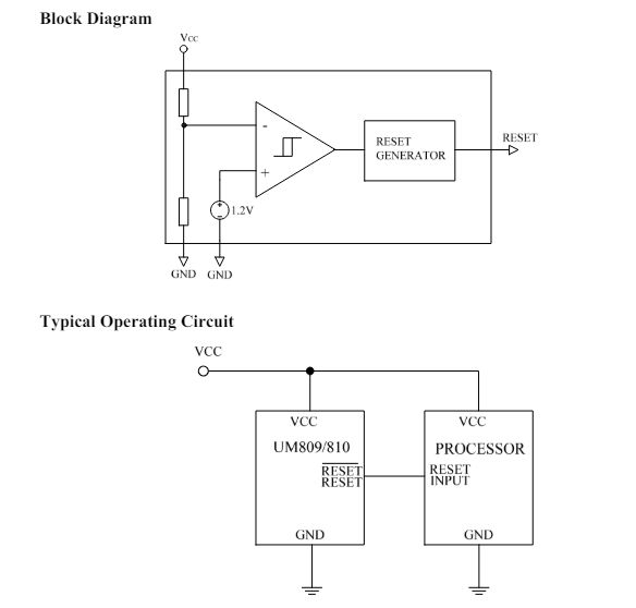
    yes, continuity between 09R GND and module GND, same for VCC to module VCC. reset leg goes to CEN

    Circuit board with an integrated circuit and electronic components along with a connection diagram.
  • Helpful post
    #19 21133154
    p.kaczmarek2
    Moderator Smart Home
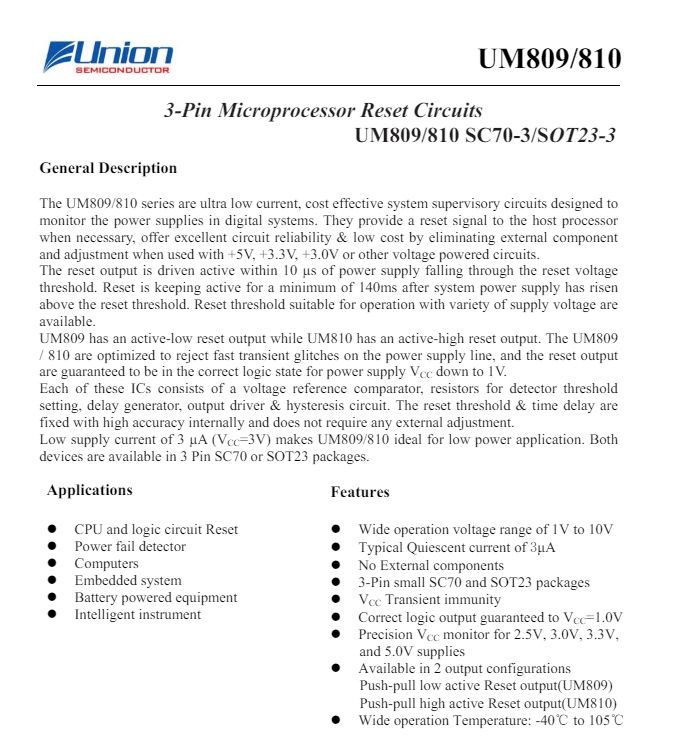
    This is both very interesting and very strange. Why would they randomly start using UM809RS (power supervisor) in this particular WiFi module?

    By the way, having this UM809RS chip on the board of Beken battery-powered sensors, may be a good way to prevent them breaking themselves while battery discharges.
    Helpful post? Buy me a coffee.
  • #20 21133163
    divadiow
    Level 35  
    that I do not know. I'm trying every angle to get a datasheet but it seems something is a secret about this module.
  • #21 21133171
    p.kaczmarek2
    Moderator Smart Home
    It reminds me of old industrial circuits that I sometimes check out in my teardowns. They often have voltage supervisor circuits next to their 8051 MCUs.
    Here's a sample one: https://www.elektroda.pl/rtvforum/topic3917123.html
    Helpful post? Buy me a coffee.

Topic summary

The discussion revolves around identifying the SM-039 module within the Woolley SA-032 smart plug, which is associated with Ewelink/Sonoff/ITEAD. The user is seeking information about the module, suspecting it may be a Trolink device, but has found no documentation confirming this. Responses include insights on the BL602 module's pin configuration, issues with power supply when using different firmware, and suggestions for troubleshooting, such as measuring current usage and improving wire connections to reduce voltage drops. The conversation also touches on the presence of an UM809RS power supervisor chip on the board, raising questions about its purpose in the design. The user expresses frustration over the lack of available datasheets and proprietary information from Sonoff.
Summary generated by the language model.
ADVERTISEMENT