Hello
I present my efforts with an Elivco 20A smart plug with power monitoring features. I first saw this variant in this thread here when sithyoda posted about a new Tuya module, the WL2S, which uses a Lightning Semiconductor LN882HKI chip. Fast-forward a few weeks and OpenBeken was developed to run on the LN882H chips thanks to the hard work of several posters in that thread. @p.kaczmarek2 has now posted a LN882H flashing guide here.
Other LN882H based modules and devices are being seen, including the usual 16A DIY mini switches of the Cozylife flavour.
This smart plug is not labelled as Elivco or LSPA9, as seen on @sithyoda's original post, but is instead marked as a BSD34, which is also seen here using a CB2S module and branded as Ledlux. It's also been seen with an ESP module in the past.
As with most of my toys, this was purchased from Ali Express, specifically from the Digitaling store.
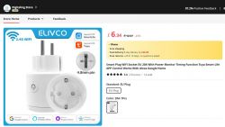
I live in the UK, so have no immediate use for an EU plug, but I was intrigued to get my own WL2S to open and flash with OpenBK.
External pics of the unit and packaging received 5 days after the order was placed:
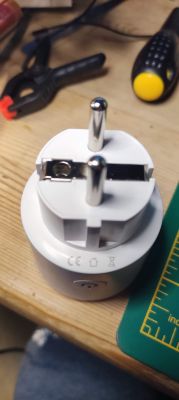
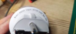
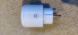
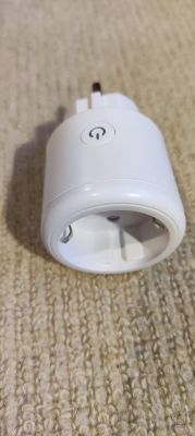
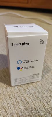
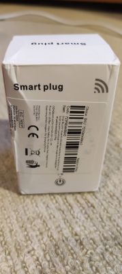
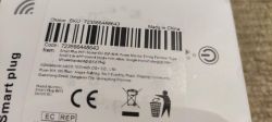
From teardowns in other posts, and by visual inspection, it was obvious where the unit would open up, -where the unit was glued/clipped along the top rim. Not happy with how some of the UK plug I've had to open have turned out, all gnarled up and battered, I sought a better, less destructive way. Maybe EU plugs are generally easier anyway, but this method was excellent for opening
.
The casing is a little different and I don't have F clamps, but I did use G-clamps and a bit of targeted force. Position the clamps just below the joining line then tighten until you hear the glue cracking - then loosen and move to a slightly new place and tighten again. Quite quickly the unit broke open without damage. With the top loose only the earth wire keeps the two sections joined.
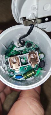
Unscrewing fully the single screw on the PCB allowed me to push the two power prongs up and out of the case. I had to loosen the earth screw slightly to move the connector round a bit to allow the PCB to slide out.
Now that it's free I can photograph the internals:
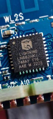
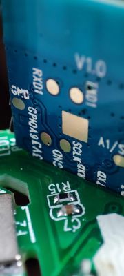
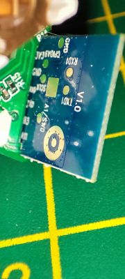

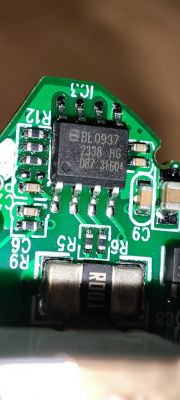
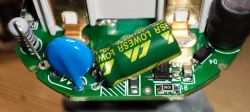
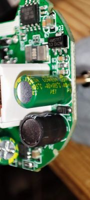
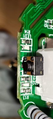
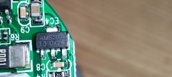
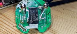
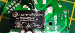
silkscreen: BSD34-202110
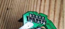
Knowing this unit has powering monitoring by way of a BL0937 chip and not wanting this to get in the way of any flashing efforts (and also the angle and position of the module makes access to some of the pads difficult for in situ flashing), I took the plunge to desolder the entire WL2S module. I first applied lots of flux to both sides of the board, covering the soldered contacts completely. I then used extra pb solder to make a single sausage blob of solder along both sides, so the factory solder was melted and mixed into one. I then pasted copper solder braid with flux and used the soldering iron to soak up all solder. Very quickly the module dropped out of the main board. This technique has been demonstrated by Elektroda:
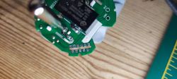
After cleaning the module with isopropyl alcohol I set up pogo pins connected to a USB-TTL adaptor, and separate (ie not the VCC from the USB adaptor) 3.3v power supply.
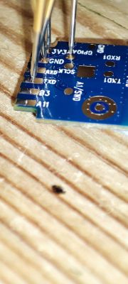
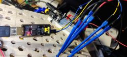
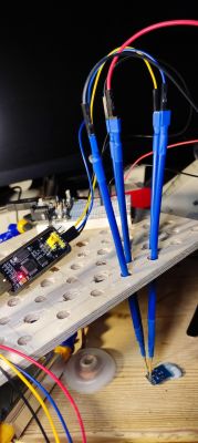
TX0 -> USB-TTL RX
RX0 -> USB-TTL TX
GND -> USB-TTL GND
3V3 -> External 3.3V PSU
External 3.3V PSU GND -> USB-TTL GND (so all 3 share a ground)
with this config, I could collect the uart boot log on power-up, which output as:
Then with A9/BOOT pad grounded I could continue with the factory flash dump and upload of the work-in-progress LN882H OBK firmware.
Unplug USB-TTL, power off external 3.3v
Plug in USB-TTL with A9/BOOT ground (and all other connections) in place
Power up 3.3v
The LN882H will see that A9 is pulled low and enter BOOT mode and await flashing.
Using a slightly modified LN882H_Flash_Dumper.py (with flash size capped at 0x00200000 after this discovery), I dumped the factory firmware which I attach to this post. I also attach the modified LN882H_Flash_Dumper.py, which will instead say complete when it hits 2mb, rather than erroring.
The dump speed is fixed and is very slow, so this took ~30-40 minutes.

After unplugging and replugging everything to reset and get into BOOT mode again, I could download (that is, download to the device from my PC) the latest OpenLN UART flash firmware. This was all done from the LN882H_CMD_TOOL (see flashing guide thread), where OpenLN882H_1.17.432.bin had been downloaded.
The output from this is just an "OK!". Thankfully this step only took a few seconds to complete.

Removing the A9/BOOT gnd and resetting the power resulted in a new "LN882H_XXX" AP to which I connected and got a 192.168.4.100 IP address.

browsing to 192.168.4.1 presents you with the OBK web config pages
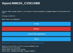
With a steady hand, plenty of flux, a small point on the soldering iron and some patience I soldered the module back in place. I think I did OK!
Thanks to @sithyoda is looks like we have the GPIOs for the BL0937 but I don't believe we can test this yet (as at 29th January 2024) as the driver is not functional.
Using the GPIO finder in the web app I was able to determine the following for the other bits
A0 LED (red)
A3 Btn
A10 LED_n (blue)
A11 Rel
which makes the OBK template for this device
I have tested this to work as expected. When off, the red LED is lit and when on the blue LED is lit. The 20A relay clicks on and off as expected.
I present my efforts with an Elivco 20A smart plug with power monitoring features. I first saw this variant in this thread here when sithyoda posted about a new Tuya module, the WL2S, which uses a Lightning Semiconductor LN882HKI chip. Fast-forward a few weeks and OpenBeken was developed to run on the LN882H chips thanks to the hard work of several posters in that thread. @p.kaczmarek2 has now posted a LN882H flashing guide here.
Other LN882H based modules and devices are being seen, including the usual 16A DIY mini switches of the Cozylife flavour.
This smart plug is not labelled as Elivco or LSPA9, as seen on @sithyoda's original post, but is instead marked as a BSD34, which is also seen here using a CB2S module and branded as Ledlux. It's also been seen with an ESP module in the past.
As with most of my toys, this was purchased from Ali Express, specifically from the Digitaling store.

I live in the UK, so have no immediate use for an EU plug, but I was intrigued to get my own WL2S to open and flash with OpenBK.
External pics of the unit and packaging received 5 days after the order was placed:


From teardowns in other posts, and by visual inspection, it was obvious where the unit would open up, -where the unit was glued/clipped along the top rim. Not happy with how some of the UK plug I've had to open have turned out, all gnarled up and battered, I sought a better, less destructive way. Maybe EU plugs are generally easier anyway, but this method was excellent for opening
The casing is a little different and I don't have F clamps, but I did use G-clamps and a bit of targeted force. Position the clamps just below the joining line then tighten until you hear the glue cracking - then loosen and move to a slightly new place and tighten again. Quite quickly the unit broke open without damage. With the top loose only the earth wire keeps the two sections joined.

Unscrewing fully the single screw on the PCB allowed me to push the two power prongs up and out of the case. I had to loosen the earth screw slightly to move the connector round a bit to allow the PCB to slide out.
Now that it's free I can photograph the internals:


silkscreen: BSD34-202110
Knowing this unit has powering monitoring by way of a BL0937 chip and not wanting this to get in the way of any flashing efforts (and also the angle and position of the module makes access to some of the pads difficult for in situ flashing), I took the plunge to desolder the entire WL2S module. I first applied lots of flux to both sides of the board, covering the soldered contacts completely. I then used extra pb solder to make a single sausage blob of solder along both sides, so the factory solder was melted and mixed into one. I then pasted copper solder braid with flux and used the soldering iron to soak up all solder. Very quickly the module dropped out of the main board. This technique has been demonstrated by Elektroda:

After cleaning the module with isopropyl alcohol I set up pogo pins connected to a USB-TTL adaptor, and separate (ie not the VCC from the USB adaptor) 3.3v power supply.


TX0 -> USB-TTL RX
RX0 -> USB-TTL TX
GND -> USB-TTL GND
3V3 -> External 3.3V PSU
External 3.3V PSU GND -> USB-TTL GND (so all 3 share a ground)
ADVERTISEMENT
with this config, I could collect the uart boot log on power-up, which output as:
bootloader build time: 13:48:19
config item not found perip_param value
-- tuya project compile time: Jun 27 2023 16:30:24--
ble mac[e3:c7:f2:e1:82:c4]
[BLIB_I]BLIB Ver: 1.0.3 [build time:Jan 19 2023 12:14:45][0x010003ff]
xTaskCreate, name: rw_task, priority: 9, stack size: 2048
xTaskCreate, name: worker, priority: 2, stack size: 1536
xTaskCreate, name: ty_main, priority: 3, stack size: 4096
xTaskCreate, name: IDLE, priority: 0, stack size: 1024
xTaskCreate, name: Tmr Svc, priority: 10, stack size: 2048
Before enter tuya_main, Total:165888; Free:153552
GPIOA_9 high level, will enter Normal mode!
Failed to enter ate mode! Start tuya user main.
xTaskCreate, name: tuya_app_main, priority: 4, stack size: 4096
xTaskCreate, name: TUYA_TCPIP, priority: 9, stack size: 2048
tkl_ethernetif_init
tkl_ethernetif_init
[01-01 00:00:00 ty I][lr:0x100b662b] mqc app init ...
xTaskCreate, name: wq_system, priority: 3, stack size: 5120
[01-01 00:00:00 ty I][tal_thread.c:184] thread_create name:wq_system,stackDepth:                                                                                   5120,totalstackDepth:7168,priority:3
xTaskCreate, name: wq_highpri, priority: 4, stack size: 4096
[01-01 00:00:00 ty I][tal_thread.c:184] thread_create name:wq_highpri,stackDepth                                                                                   :4096,totalstackDepth:11264,priority:4
xTaskCreate, name: sys_timer, priority: 5, stack size: 4096
[01-01 00:00:00 ty D][tal_thread.c:203] Thread:wq_highpri Exec Start. Set to Run                                                                                   ning Stat
[01-01 00:00:00 ty D][tal_thread.c:203] Thread:sys_timer Exec Start. Set to Runn                                                                                   ing Stat
[01-01 00:00:00 ty I][tal_thread.c:184] thread_create name:sys_timer,stackDepth:                                                                                   4096,totalstackDepth:15360,priority:5
[01-01 00:00:00 ty D][lr:0x10078c65] init fs. Path: null
[01-01 00:00:00 ty D][lr:0x100aa331] *****************kvs_init.
[01-01 00:00:00 ty D][lr:0x100cdbe1] protected init. addr:0x001eb000
[01-01 00:00:00 ty D][lr:0x100cd9f1] init protected data length 495
[01-01 00:00:00 ty N][lr:0x100ac72b] key_addr: 0x1ec000   block_sz 4096
[01-01 00:00:00 ty N][lr:0x100aca05] get key:
0xaf 0x5 0x23 0x8e 0x2b 0xbe 0xbc 0x6f 0xda 0xc6 0x16 0x50 0x76 0x4d 0x78 0xbb
[01-01 00:00:00 ty D][lr:0x100cdbff] protected verify begin
[01-01 00:00:00 ty D][lr:0x100cdc61] check [gw_bi][282]
[01-01 00:00:00 ty D][lr:0x100cdc61] check [gw_wsm][141]
[01-01 00:00:00 ty D][lr:0x100cdc81] protected verify end
[01-01 00:00:00 ty D][lr:0x100ab97f] begin try update kv version
[01-01 00:00:00 ty D][lr:0x100ab99b] pre kv version is 2
[01-01 00:00:00 ty D][lr:0x100acea1] 111 k=3  i=18 0
[01-01 00:00:00 ty N][lr:0x100b2729] uni_random_init...
[01-01 00:00:00 ty N][lr:0x100b29cd] tuya_tls_rand_init ok!
[01-01 00:00:00 ty D][lr:0x10090ef9] init watchdog, interval: 60
----- tkl_watchdog_init
wdg shift_left_num:0x10, set num:65535, top:0x0d
[01-01 00:00:00 ty D][lr:0x10090e4b] add new node,type:0
[01-01 00:00:00 ty D][lr:0x10090e4b] add new node,type:1
[01-01 00:00:00 ty D][lr:0x10090e4b] add new node,type:2
[01-01 00:00:00 ty D][lr:0x10090e4b] add new node,type:3
[01-01 00:00:00 ty D][lr:0x10090e4b] add new node,type:4
[01-01 00:00:00 ty D][lr:0x10090e4b] add new node,type:5
[01-01 00:00:00 ty D][lr:0x10090e4b] add new node,type:6
[01-01 00:00:00 ty D][lr:0x10090e4b] add new node,type:7
[01-01 00:00:00 ty D][lr:0x10090e4b] add new node,type:8
[01-01 00:00:00 ty D][lr:0x10091009] watch_dog_interval:60, monitor_detect_inter                                                                                   val:600
xTaskCreate, name: health_monitor, priority: 5, stack size: 1536
[01-01 00:00:00 ty D][tal_thread.c:203] Thread:health_monitor Exec Start. Set to                                                                                    Running Stat
[01-01 00:00:00 ty I][tal_thread.c:184] thread_create name:health_monitor,stackD                                                                                   epth:1536,totalstackDepth:16896,priority:5
[01-01 00:00:00 ty D][lr:0x100b6531] mq_pro:5 cnt:1
[01-01 00:00:00 ty D][lr:0x100b6531] mq_pro:31 cnt:2
[01-01 00:00:00 ty D][lr:0x100b15b5] svc online log init success
[01-01 00:00:00 ty E][lr:0x100b5d3f] logseq empty
[01-01 00:00:00 ty N][lr:0x1006afcf] < TuyaOS V:3.5.4 BS:40.00_PT:2.3_LAN:3.5_CA                                                                                   D:1.0.5_CD:1.0.0 >
< BUILD AT:2023_01_09_16_12_01 BY ci_manage FOR tuyaos-iot AT ln882h >
IOT DEFS < WIFI_GW:1 DEBUG:1 KV_FILE:0 LITTLE_END:1 SL:0 OPERATING_SYSTEM:98 REL                                                                                   IABLE_TRANSFER:0 >

[01-01 00:00:00 ty N][lr:0x1006afd9] ln_elec_plug:1.0.4
[01-01 00:00:00 ty N][lr:0x1006afe3] firmware compiled at Jul  5 2023 15:01:06
[01-01 00:00:00 ty N][lr:0x1006affd] REST INFORMATION IS 0
[01-01 00:00:00 ty N][lr:0x1006b25f] ,over_vol: is 0
[01-01 00:00:00 ty N][lr:0x1006b25f] ,lose_vol: is 0
[01-01 00:00:00 ty N][lr:0x1006b25f] ,over_cur: is 20000
[01-01 00:00:00 ty N][lr:0x1006b28f] ,chip_type: is 0
[01-01 00:00:00 ty N][lr:0x1006b28f] ,ele_fun_en: is 1
[01-01 00:00:00 ty N][lr:0x1006b25f] ,ele_pin: is 26
[01-01 00:00:00 ty N][lr:0x1006b25f] ,vi_pin: is 8
[01-01 00:00:00 ty N][lr:0x1006b25f] ,sel_pin_lv: is 1
[01-01 00:00:00 ty N][lr:0x1006b25f] ,sel_pin_pin: is 24
[01-01 00:00:00 ty N][lr:0x1006b25f] ,resistor: is 1
[01-01 00:00:00 ty N][lr:0x1006b28f] ,vol_def: is 0
[01-01 00:00:00 ty D][lr:0x1006b1dd] ,zero_select: is not exsit  1
[01-01 00:00:00 ty D][lr:0x1006b1dd] ,zero_t: is not exsit  1
[01-01 00:00:00 ty D][lr:0x1006b1dd] ,zero_io_pin: is not exsit  1
[01-01 00:00:00 ty N][lr:0x1006b28f] ,ffc_select: is 0
[01-01 00:00:00 ty N][lr:0x1006b28f] ,rl1_type: is 0
[01-01 00:00:00 ty D][lr:0x1006b1dd] ,rl_type: is not exsit  1
[01-01 00:00:00 ty D][lr:0x1006b1dd] ,rl1_drvtime: is not exsit  1
[01-01 00:00:00 ty D][lr:0x1006b1dd] ,rl_drvtime: is not exsit  1
[01-01 00:00:00 ty N][lr:0x1006b28f] ,jv: is 1.0.4
[01-01 00:00:00 ty N][lr:0x1006b28f] ,module: is CB2S
[01-01 00:00:00 ty N][lr:0x1006b28f] ,net_trig: is 4
[01-01 00:00:00 ty D][lr:0x1006b1dd] ,total_led_lv: is not exsit  1
[01-01 00:00:00 ty D][lr:0x1006b1dd] ,total_led_pin: is not exsit  1
[01-01 00:00:00 ty D][lr:0x1006b1dd] ,total_bt_lv: is not exsit  1
[01-01 00:00:00 ty D][lr:0x1006b1dd] ,total_bt_pin: is not exsit  1
[01-01 00:00:00 ty D][lr:0x1006b1dd] ,bt_type: is not exsit  1
[01-01 00:00:00 ty N][lr:0x1006b28f] ,bt1_type: is 0
[01-01 00:00:00 ty N][lr:0x1006b25f] ,netled1_lv: is 0
[01-01 00:00:00 ty N][lr:0x1006b25f] ,netled1_pin: is 7
[01-01 00:00:00 ty N][lr:0x1006b28f] ,nety_led: is 0
[01-01 00:00:00 ty N][lr:0x1006b28f] ,netn_led: is 1
[01-01 00:00:00 ty N][lr:0x1006b28f] ,netled_reuse: is 0
[01-01 00:00:00 ty N][lr:0x1006b25f] ,reset_t: is 5
[01-01 00:00:00 ty N][lr:0x1006b28f] ,ch1_stat: is 2
[01-01 00:00:00 ty D][lr:0x1006b1dd] ,total_stat: is not exsit  1
[01-01 00:00:00 ty N][lr:0x1006b25f] ,ch_num: is 1
[01-01 00:00:00 ty N][lr:0x1006b131] channal num is 1
[01-01 00:00:00 ty N][lr:0x1006b38b] ,rl1_lv: is 1
[01-01 00:00:00 ty N][lr:0x1006b38b] ,rl1_pin: is 6
[01-01 00:00:00 ty D][lr:0x1006b31d] ,rl_on1_lv: is not exsit 5
[01-01 00:00:00 ty D][lr:0x1006b31d] ,rl_on1_pin: is not exsit 5
[01-01 00:00:00 ty D][lr:0x1006b31d] ,rl_off1_lv: is not exsit 5
[01-01 00:00:00 ty D][lr:0x1006b31d] ,rl_off1_pin: is not exsit 5
[01-01 00:00:00 ty N][lr:0x1006b38b] ,bt1_lv: is 0
[01-01 00:00:00 ty N][lr:0x1006b38b] ,bt1_pin: is 10
[01-01 00:00:00 ty N][lr:0x1006b38b] ,led1_lv: is 0
[01-01 00:00:00 ty N][lr:0x1006b38b] ,led1_pin: is 23
[01-01 00:00:00 ty N][lr:0x1006b38b] ,ch_dpid1: is 1
[01-01 00:00:00 ty N][lr:0x1006b38b] ,ch_cddpid1: is 9
[01-01 00:00:00 ty D][lr:0x1006b1dd] ,ble_pair_time: is not exsit  1
[01-01 00:00:00 ty D][lr:0x1006b6b3] get_measure_chip_type is 0
[01-01 00:00:00 ty D][lr:0x1006b727] get_standard_vol is 0
[01-01 00:00:00 ty D][lr:0x1006b6b3] get_measure_chip_type is 0
[01-01 00:00:00 ty N][lr:0x1006b929] product have measure , chip is 0 vol is 220                                                                                   0  res is 1
[01-01 00:00:00 ty D][lr:0x10078c65] init fs. Path: null
[01-01 00:00:00 ty D][lr:0x100aa331] *****************kvs_init.
[01-01 00:00:00 ty N][lr:0x10097513] mf is open need stop fastconnect
[01-01 00:00:00 ty D][lr:0x1007b151] mf_core_init success
[01-01 00:00:00 ty D][lr:0x100cde05] protected read [gw_bi]
[01-01 00:00:00 ty D][lr:0x100cde93] protected read ret:0 length:282
[01-01 00:00:00 ty D][lr:0x1008e8eb] gw_bi read ret:0
set work mode 1, is open 0, current ln mode: 0
wifi not start, turn on first
adapt wifi start <m:1>, hw_ready:0
start rf preprocess and image cal
[WLIB_E]idx=00, iq_hex_cal=0x7B7F, i=123, q=127, iavg= 35, qavg= 37
[WLIB_E]idx=01, iq_hex_cal=0x797C, i=121, q=124, iavg= 69, qavg=  3
[WLIB_E]idx=02, iq_hex_cal=0x7679, i=118, q=121, iavg= 10, qavg=  4
[WLIB_E]idx=03, iq_hex_cal=0x7173, i=113, q=115, iavg= 25, qavg= 72
[WLIB_E]idx=04, iq_hex_cal=0x6870, i=104, q=112, iavg=  4, qavg= 47
[WLIB_E]idx=05, iq_hex_cal=0x7B7F, i=123, q=127, iavg= 52, qavg= 38
[WLIB_E]idx=06, iq_hex_cal=0x7A7D, i=122, q=125, iavg= 46, qavg=  7
[WLIB_E]idx=07, iq_hex_cal=0x7779, i=119, q=121, iavg= 57, qavg=  9
[WLIB_E]idx=08, iq_hex_cal=0x7273, i=114, q=115, iavg= 35, qavg= 89
[WLIB_E]idx=09, iq_hex_cal=0x6A70, i=106, q=112, iavg=  9, qavg= 44
[WLIB_E]idx=10, iq_hex_cal=0x7B7F, i=123, q=127, iavg= 55, qavg= 39
[WLIB_E]idx=11, iq_hex_cal=0x7A7D, i=122, q=125, iavg= 40, qavg=  3
[WLIB_E]idx=12, iq_hex_cal=0x7779, i=119, q=121, iavg= 51, qavg= 11
[WLIB_E]idx=13, iq_hex_cal=0x7273, i=114, q=115, iavg= 38, qavg= 77
[WLIB_E]idx=14, iq_hex_cal=0x6B70, i=107, q=112, iavg=  4, qavg= 58
[WLIB_E]idx=15, iq_hex_cal=0x7B7F, i=123, q=127, iavg= 54, qavg= 34
[WLIB_E]idx=16, iq_hex_cal=0x7A7C, i=122, q=124, iavg= 40, qavg=  3
[WLIB_E]idx=17, iq_hex_cal=0x7778, i=119, q=120, iavg= 50, qavg=  3
[WLIB_E]idx=18, iq_hex_cal=0x7274, i=114, q=116, iavg= 49, qavg= 72
[WLIB_E]idx=19, iq_hex_cal=0x6A70, i=106, q=112, iavg=  9, qavg= 79
[WLIB_E]idx=20, iq_hex_cal=0x7A7F, i=122, q=127, iavg= 29, qavg=100
[WLIB_E]idx=21, iq_hex_cal=0x787E, i=120, q=126, iavg= 38, qavg= 46
[WLIB_E]idx=22, iq_hex_cal=0x747B, i=116, q=123, iavg= 41, qavg= 51
[WLIB_E]idx=23, iq_hex_cal=0x6E78, i=110, q=120, iavg= 51, qavg= 78
[WLIB_E]idx=24, iq_hex_cal=0x6376, i= 99, q=118, iavg= 45, qavg= 52
Then with A9/BOOT pad grounded I could continue with the factory flash dump and upload of the work-in-progress LN882H OBK firmware.
Unplug USB-TTL, power off external 3.3v
Plug in USB-TTL with A9/BOOT ground (and all other connections) in place
Power up 3.3v
The LN882H will see that A9 is pulled low and enter BOOT mode and await flashing.
Using a slightly modified LN882H_Flash_Dumper.py (with flash size capped at 0x00200000 after this discovery), I dumped the factory firmware which I attach to this post. I also attach the modified LN882H_Flash_Dumper.py, which will instead say complete when it hits 2mb, rather than erroring.
python LN882H_Flash_Dumper.py COMx flashdumpThe dump speed is fixed and is very slow, so this took ~30-40 minutes.

After unplugging and replugging everything to reset and get into BOOT mode again, I could download (that is, download to the device from my PC) the latest OpenLN UART flash firmware. This was all done from the LN882H_CMD_TOOL (see flashing guide thread), where OpenLN882H_1.17.432.bin had been downloaded.
LN882H_CMD_Tool.exe COM9 download flash 2000000 0x0 OpenLN882H_1.17.432.binThe output from this is just an "OK!". Thankfully this step only took a few seconds to complete.
Removing the A9/BOOT gnd and resetting the power resulted in a new "LN882H_XXX" AP to which I connected and got a 192.168.4.100 IP address.

browsing to 192.168.4.1 presents you with the OBK web config pages

With a steady hand, plenty of flux, a small point on the soldering iron and some patience I soldered the module back in place. I think I did OK!

Thanks to @sithyoda is looks like we have the GPIOs for the BL0937 but I don't believe we can test this yet (as at 29th January 2024) as the driver is not functional.
Using the GPIO finder in the web app I was able to determine the following for the other bits
A0 LED (red)
A3 Btn
A10 LED_n (blue)
A11 Rel
which makes the OBK template for this device
Code: JSON
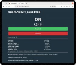
I have tested this to work as expected. When off, the red LED is lit and when on the blue LED is lit. The 20A relay clicks on and off as expected.
Cool? Ranking DIY


![[LN882H] [WL2S] Elivco 20A BSD34 EU Power Monitoring Plug [BL0937] [LN882H] [WL2S] Elivco 20A BSD34 EU Power Monitoring Plug [BL0937]](https://obrazki.elektroda.pl/5616128200_1707497772_thumb.jpg)
