FAQ
TL;DR: For 30 m runs, don’t send 3.3 V GPIO directly. Use local 5 V power at the relays and drive the optocouplers with a higher‑level signal; one user even ran 5 V over ~70 m — “I used to do about 70m on 5V.” [Elektroda, ArturAVS, post #21143153]
Why it matters: This avoids voltage drop headaches and makes long‑distance ESP‑to‑relay control reliable and safe for DIYers and field techs.
Quick Facts
- 3.3 V logic over 30 m is unreliable; change the concept or the signaling level. [Elektroda, Anonymous, post #21143122]
- A 24 V supply is available at the valve end; leverage it for signaling or local power. [Elektroda, PawelJuszczak, post #21147054]
- Target about 5 mA into the optocoupler LED; keep the relay board on clean 5 V. [Elektroda, Anonymous, post #21147407]
- Expect voltage drop on a 30 m twisted pair; place power near loads to avoid it. [Elektroda, madamsz1, post #21147466]
- Field report: ~70 m on 5 V signaling worked, but design conservatively. [Elektroda, ArturAVS, post #21143153]
How should I wire an ESP to control relays 30 m away?
Keep the relay module powered locally at 5 V near the valves. Use the 24 V line for signaling into the input optocouplers through a series resistor that sets about 5 mA LED current. Tie grounds only where required by the boards’ guidance. [Elektroda, Anonymous, post #21147407]
Is 30 m too far for a 3.3 V GPIO line?
Yes. 3.3 V over 30 m is marginal due to drop and noise susceptibility. Switch to higher‑level signaling or a different concept, then isolate at the relay inputs. “30m is a lot for 3.3V.” [Elektroda, Anonymous, post #21143122]
Can I just run 5 V logic over that distance?
It can work. One practitioner reports about 70 m on 5 V logic, though design margins are tight and environment‑dependent. Quote: “I used to do about 70m on 5V.” Prefer using local power and opto inputs for robustness. [Elektroda, ArturAVS, post #21143153]
How do I use 24 V to safely drive the relay board’s optocouplers?
Feed the optocoupler input through a calculated series resistor so the input LED sees about 5 mA. This uses the existing 24 V near the valves while keeping the relay board itself on stable 5 V power. [Elektroda, kindlar, post #21147214]
My module says 3.3/5 V control only—can 24 V still be used?
Yes, but only through the optocoupler input with proper current limiting or by modifying the front‑end network. Guidance includes removing jumpers and changing the input resistor on the “817” board for the desired input path. Verify GND/RGND before wiring. [Elektroda, Anonymous, post #21147716]
Where should I place the relay board and power supplies?
Place power near the loads and isolate control. Keep the relay board and its 5 V supply close to the valves. Use the available 12/24 V at that end for signaling or supply, reducing drop and noise on long runs. [Elektroda, madamsz1, post #21143291]
Can I use the twisted pair to feed 24 V to the solenoid valves?
You can, but expect voltage drop because valves draw real current. Long, thin twisted pairs add resistance. Better: put the power supply near the valves and run only the low‑current control signal over the pair. [Elektroda, madamsz1, post #21147466]
How do I size the resistor for ~5 mA into the optocoupler LED from 24 V?
Three steps: 1) Confirm the input is the optocoupler LED path. 2) Choose a resistor that limits LED current to about 5 mA from 24 V. 3) Wire 24 V → resistor → IN, and return to the relay board input ground as designed. [Elektroda, Anonymous, post #21147407]
Do I need a common ground between ESP and the remote module?
Check your board markings. Some “817” boards separate logic GND and RGND. Verify with an ohmmeter whether they are common before deciding. Wrong grounding can defeat isolation or prevent operation. [Elektroda, Anonymous, post #21147716]
What if I keep the relays near the ESP and send valve power 30 m?
Expect drops on the long power run, especially during valve inrush. The forum advice favors local power at the load and sending only conditioned control signals over distance. This improves reliability. [Elektroda, madamsz1, post #21147466]
Can I modify the “817” input to make low‑voltage control work better?
Yes. Users suggest removing the jumper and changing the series resistor on the “817” module to alter sensitivity. Follow the specific board’s silkscreen and confirm GND/RGND behavior before powering. [Elektroda, Anonymous, post #21147716]
What failure edge cases should I watch for with the 817 board?
A short at the 817 module output can overheat the optoisolator if jumpers route power incorrectly. Recheck jumper positions and resistor changes before tests. Quote: “be careful because such a connection… will heat up the optoisolator.” [Elektroda, Anonymous, post #21147716]


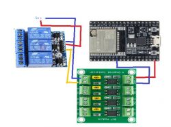
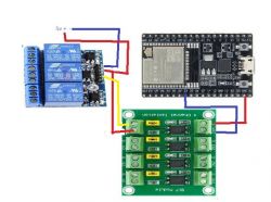
 I tried it like this.


