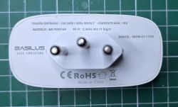
This BASILUS Smart Plug is quite common in Brazil and offers energy meter functionality when connected to Tuya.
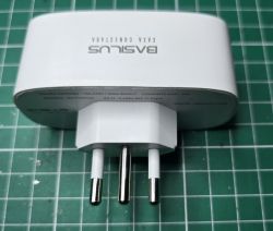
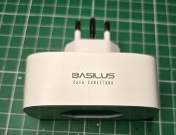
To begin our teardown process we can star disassembling the device from the back.
I used a thin knife near the edges until it started coming apart, with little to no damage to the outer casing. Doing so reveals the internal components:
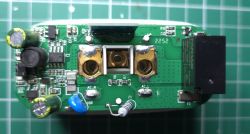
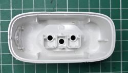
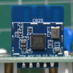
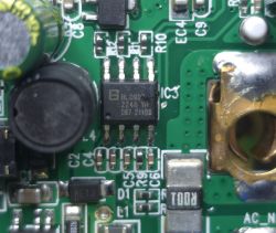
We can see that this smart plug uses a BK7231N in a separate board as the microcontroller and BL0937 IC for energy metering:
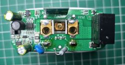
Unfortunately, we cannot immediately access the RX1 and TX1 pads on the microcontroller, so we first need to desolder the main PCB from the case in the following places:
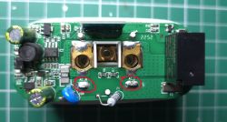
After desoldering, we can remove the main PCB from the casing:
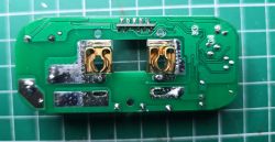
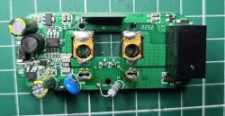
And now we can solder the GND, 3.3V, RX and TX wires according to the images below:
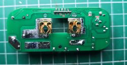
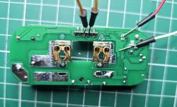
With all wires connected, we connect them to a computer using a serial adapter. Now we can download and run the flasher tool from https://github.com/openshwprojects/BK7231GUIFlashTool . Make sure to select the right COM port and change the chip type to BK7231N.
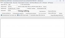
After that we can select "Do backup and flash new" and power cycle the microcontroller. The flash tool should read the current firmware and flash OpenBeken:
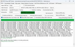
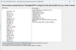
If everything went well, we can power cycle the microcontroller one more time and after a few seconds a new wifi network should appear. We can connect to that network and open the address 192.168.4.1 in a web browser to see the configuration page for OpenBeken. Now we can go to Config -> Configure WiFi & Web and type our SSID and password.
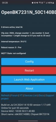
After some time the Smart Plug should connect to the Wifi and you can enter the web page again using its IP. Depending on your network configuration, you can find the IP address of the device by running the command nslookup DEVICE_NAME.local (in my case OpenBK7231N_50C140BD).
To finish configuring the Smart Plug, go to Launch Web Application and Import. The configuration found by the flasher is already very good, we just need to invert the signals for both LEDs, load the BL0937 and NTP drivers and setup energy stats to get power metering. You can import the following configuration:
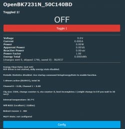
After importing the configuration, go to OTA -> Reboot and you can go to the main web page to test if the relay is working properly:
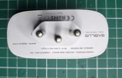
Now it's time to solder the PCB back to the contact points. Be careful during this step to make sure you get a good connection and prevent any issues in the future. The final mechanical step is to close the case with a bit of glue on the edges:
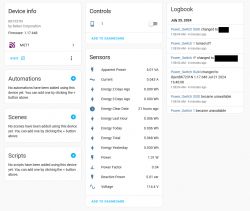
To add the device to Home Assistant, change its short name, configure MQTT and enable auto discovery. For more information on this process, you can follow the official video guide: https://www.youtube.com/watch?v=pkcspey25V4&list=PLzbXEc2ebpH0I8m_Cfbqv1MTlQuBKYvlx
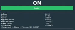
As a last step, you can calibrate the energy meter IC to get more accurate results. For this, head to the Tools tab in the Web application and find the Power metering section. First, you should measure the voltage using a multimeter, type the value in Voltage, and apply it. Then, you should connect a pure resistive load (such as an incandescent bulb or hair dryer) in the socket, in series with a multimeter in current mode. Turn on the socket, mesaure the current, type it in Current and apply. Finally, since the load is purely resistive, we can assume a factor of 1, so to calculate the real power you can multiply the voltage measured by the socket with the current measured by the multimeter. Type that value in Power and apply. This should get you fairly accurate results:


To begin our teardown process we can star disassembling the device from the back.

I used a thin knife near the edges until it started coming apart, with little to no damage to the outer casing. Doing so reveals the internal components:


We can see that this smart plug uses a BK7231N in a separate board as the microcontroller and BL0937 IC for energy metering:


Unfortunately, we cannot immediately access the RX1 and TX1 pads on the microcontroller, so we first need to desolder the main PCB from the case in the following places:

After desoldering, we can remove the main PCB from the casing:


And now we can solder the GND, 3.3V, RX and TX wires according to the images below:


With all wires connected, we connect them to a computer using a serial adapter. Now we can download and run the flasher tool from https://github.com/openshwprojects/BK7231GUIFlashTool . Make sure to select the right COM port and change the chip type to BK7231N.

After that we can select "Do backup and flash new" and power cycle the microcontroller. The flash tool should read the current firmware and flash OpenBeken:


If everything went well, we can power cycle the microcontroller one more time and after a few seconds a new wifi network should appear. We can connect to that network and open the address 192.168.4.1 in a web browser to see the configuration page for OpenBeken. Now we can go to Config -> Configure WiFi & Web and type our SSID and password.

After some time the Smart Plug should connect to the Wifi and you can enter the web page again using its IP. Depending on your network configuration, you can find the IP address of the device by running the command nslookup DEVICE_NAME.local (in my case OpenBK7231N_50C140BD).

To finish configuring the Smart Plug, go to Launch Web Application and Import. The configuration found by the flasher is already very good, we just need to invert the signals for both LEDs, load the BL0937 and NTP drivers and setup energy stats to get power metering. You can import the following configuration:
Code: JSON
After importing the configuration, go to OTA -> Reboot and you can go to the main web page to test if the relay is working properly:

Now it's time to solder the PCB back to the contact points. Be careful during this step to make sure you get a good connection and prevent any issues in the future. The final mechanical step is to close the case with a bit of glue on the edges:


To add the device to Home Assistant, change its short name, configure MQTT and enable auto discovery. For more information on this process, you can follow the official video guide: https://www.youtube.com/watch?v=pkcspey25V4&list=PLzbXEc2ebpH0I8m_Cfbqv1MTlQuBKYvlx

As a last step, you can calibrate the energy meter IC to get more accurate results. For this, head to the Tools tab in the Web application and find the Power metering section. First, you should measure the voltage using a multimeter, type the value in Voltage, and apply it. Then, you should connect a pure resistive load (such as an incandescent bulb or hair dryer) in the socket, in series with a multimeter in current mode. Turn on the socket, mesaure the current, type it in Current and apply. Finally, since the load is purely resistive, we can assume a factor of 1, so to calculate the real power you can multiply the voltage measured by the socket with the current measured by the multimeter. Type that value in Power and apply. This should get you fairly accurate results:


