logo elektroda
logo elektroda
X
logo elektroda

[T34/BL0937] Teardown Generic Wifi Smart Plug with Energy Measurement

Raufaser 17445 132
ADVERTISEMENT
  • #1 21003264
    Raufaser
    Level 10  
    I ordered some more cheap Smart Sockets / Smart Plugs from a big chinese online warehouse.
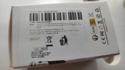
    The box with a badly copied label.
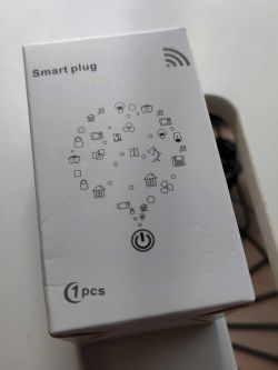
    White box with Smart plug label and icons of various devices. White box with a label featuring a barcode and product information, including CE markings and Made in China.

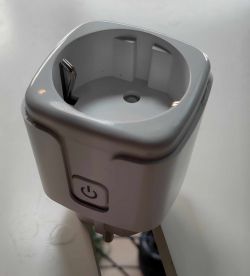
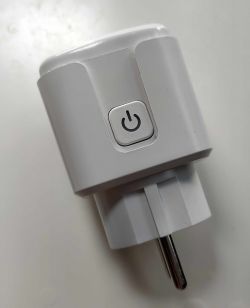
    The plug itself has label or so.
    Close-up of a smart plug with a power button. Photo of a white smart plug with a power button on the casing.

    Then i got my good old Tamron Macro lens and took some pictures of the internals.
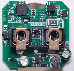
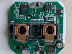
    Close-up of the inside of a smart plug showing electronic components on a green circuit board.

    Better lighting on the interesting chips:
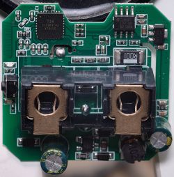
    Close-up of the interior of a smart plug showing electronic components.

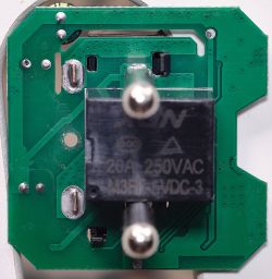
    And the backside:
    Close-up of the interior of a smart plug showing a green circuit board and a black relay.

    Soldering the wires to flash it seems to be not that easy. I will try that now and post my experience.
  • ADVERTISEMENT
  • #2 21005230
    p.kaczmarek2
    Moderator Smart Home
    This indeed looks like somewhat problematic. Are TX1/RX1 routed out anywhere, maybe to a button or a LED?

    If not, in the worst case scenario, you can desolder T34 itself and use approach from this topic:
    https://www.elektroda.com/rtvforum/topic4036975.html

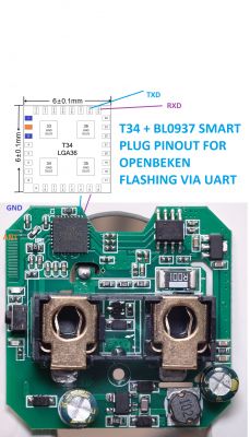
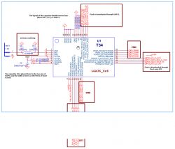
    Hm, I did a brief analysis myself, it seems that only one of UART lines is broken out. You need some flux and some precise soldering.
    Pinout diagram of T34 and BL0937 smart plug with a PCB view
    Helpful post? Buy me a coffee.
  • ADVERTISEMENT
  • #3 21005344
    Raufaser
    Level 10  

    At first i tried to solder the wires to the T34 as it was still soldered to the board. It didn't work.
    Then i desoldered the T34 from the board using my rework station. I soldered the wires directly to the pads on the bottom of the T34. Unfortunately i seem to have too much leverage when i was connecting the cables to the UART-USB converter and the pad 25 fell off the T34. So RIP my T34 XD

    I would try to avoid these kind of plugs. Much harder to work with than the user variants. I will try to get these probe tips for the next time.
    This is the item i bought. Maybe it helps someone to avoid it. Or if he is seeking for adventure, to get exactly this one.
  • #4 21005347
    p.kaczmarek2
    Moderator Smart Home
    The problem is it looks like a classic LSPA9 device, already described in several versions on our forum. I already had ESP8266-based LSPA9s, WB2S and CB2S based ones. So it's hard to tell from the outside which version you'll get.


    Helpful post? Buy me a coffee.
  • #5 21029565
    rufus4
    Level 10  

    Today I received three smart plugs like the ones here in the pictures from @Raufaser.

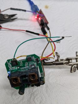
    I did try to solder the critical RXD wire directly to the microprocessor and had luck. TXD was easy because of the missing resistance and 3V3 / GND are as well easy to solder. CEN is not needed.

    After a few times trying to backup the original FW always ending in errors I did flash the T34 with newest OpenBeken. For sure I must have done something wrong with the backup process, but so far everything else works well.
    Now I do have to find the right pins and make things working again.

    Before messing everything up I did measure the power consumption of the device with the Tuya FW. And was surprised about efficiency: 2.5-5mA relay off and 6.5-8.5 relay on There must be something wrong about measuring after my isolating-transformator. Measured again and now it's 5-7mA relay off and 11-15mA relay on.
    And it seems that they set a power save mode even with the BL0937.

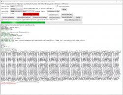
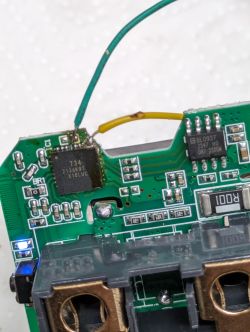
    Screenshot of BK7231 Easy UART Flasher showing a Reading failed error during firmware backup attempt. Close-up of a circuit board with several chips and soldered wires.The image shows an open smart plug with visible solder joints and wires.

    Is there something special to know for backing up original FW? So I can try with the other two devices. (I only did experiment with different baud rates, but this was not the problem.)
  • #6 21030449
    rufus4
    Level 10  
    --updated--

    Pin setting is quiet tricky because T34 and BK7231N have completely different pinouts. (pin numbers are different)
    Wiring diagram of the T34 system with pin and connector descriptions.

    So far I found these pins working:
    
    {
      "vendor": "Tuya",
      "bDetailed": "0",
      "name": "Full Device Name Here",
      "model": "enter short model name here",
      "chip": "BK7231N",
      "board": "TODO",
      "flags": "1024",
      "keywords": [
        "TODO",
        "TODO",
        "TODO"
      ],
      "pins": {
        "6": "BL0937CF;0",
        "7": "BL0937CF1;0",
        "8": "BL0937SEL;0",
        "24": "Rel;0",
        "26": "Btn;0",
        "28": "WifiLED;0"
      },
      "command": "",
      "image": "https://obrazki.elektroda.pl/YOUR_IMAGE.jpg",
      "wiki": "https://www.elektroda.com/rtvforum/topic_YOUR_TOPIC.html"
    }


    Added after 4 [hours] 6 [minutes]:

    optional startup command text:
    backlog startDriver NTP; ntp_setServer 192.168.1.1; ntp_timeZoneOfs +1; PowerSave 1


    optional autoexec.bat:
    
    startDriver NTP
    ntp_setServer 192.168.1.1
    ntp_timeZoneOfs +1
    
    PowerSave 1


    Additional setting:
    -remember relay channel state -1 at startup

    Maybe there are still some optimizations missing. But like this, everything works perfect.

    And once more mesured amps now whith all services working: 8mA and 16mA with relay on. (PowerSave 0)
    PowerSave 1 works after some minutes. 6-8mA and 11-15mA with relay on (mesured with clamp ammeter)
    and even less without open GUI in browser it is 4-6mA and 9-13mA.
    Power consumption looks the same like with original FW and is very efficient.

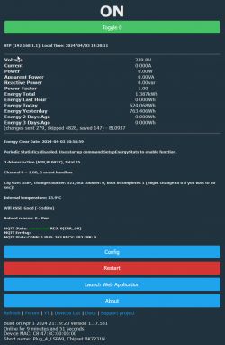
    Screenshot of a remote-controlled device interface displaying energy data.

    Now I did magage to backup the original Tuya FW:
    readResult...-57-17.bin Download (2 MB)
  • #7 21031175
    Mickaelf
    Level 3  

    hi, thank you for the work, you were faster than me, in your configuration you put "28": "LED_n;0" but this pin is that of the wifi led replaced by "28": "WifiLED_n;0" and you have the two LEDs that work, I just tested.
  • ADVERTISEMENT
  • #8 21031235
    rufus4
    Level 10  
    thank you!
    So I updated my config.

    Another thing: setting PowerSave 1 doesn't make any difference. But in general it should work with BK7231N? Is this right?
    PowerSave 1 works after some minutes. 6-8mA and 11-15mA with relay on (mesured with clamp ammeter)
    Power consumption looks the same like with original FW.
  • #9 21033183
    p.kaczmarek2
    Moderator Smart Home
    Yes, PowerSave is a bit tricky. It works, but it's easy to disturb it by, for example, having the Web App Log open. Well, maybe even having the main native page open can disturb power save more or less, that's because the native main http page is also often refreshing the state of the device thus preventing it from sleeping.
    Helpful post? Buy me a coffee.
  • #10 21033260
    rufus4
    Level 10  
    That is truth. Leaving the device overnight without active GUI, power dropped much more.
    Now I can measure 4-6mA and 9-13mA with relay on with my clamp ammeter. But like I said before, there would be an oscilloscope needed for accurate measuring power consumption.

    Finally I added a DHT22 and do start to really love it, even with the T34.
  • #11 21033318
    p.kaczmarek2
    Moderator Smart Home
    I am glad to hear it's working. It is also worth to mention that PowerSave is implemened on the most of our supported platforms (well, maybe except LN882H, currently). For example, here is a PowerSave test on WinnerMicro chip:


    Helpful post? Buy me a coffee.
  • #12 21038938
    Raufaser
    Level 10  

    Raufaser wrote:

    So RIP my T34 XD


    Yesterday I thought: "Hold my beer, while I try to unrip my T34"

    [T34/BL0937] Teardown Generic Wifi Smart Plug with Energy Measurement

    You can see the ripped off pad No. 26 (which is TXD) Under the microscope, I could see, that there is a tiny trace under the coating going to a slightly bigger trace very close to pad No. 24. So i took a very fine needle and started to scrape off the coating. I was able to get to the underlying trace without damaging it. Soldering something to it didn't work. Everything fell off. So:

    [T34/BL0937] Teardown Generic Wifi Smart Plug with Energy Measurement [T34/BL0937] Teardown Generic Wifi Smart Plug with Energy Measurement [T34/BL0937] Teardown Generic Wifi Smart Plug with Energy Measurement

    It worked :) I was even able to dump the firmware. And then I flashed OpenBeken :D
    readResult...-03-06.zip Download (1.04 MB)

    To establish a connection, I had to solder the chip back in place. I have never soldered QFN before. But even that i managed to do.

    [T34/BL0937] Teardown Generic Wifi Smart Plug with Energy Measurement

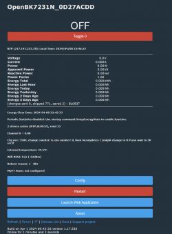
    The energy measurement isn't working.

    User interface displaying the status of the OpenBK7231N device

    At first I was wondering why, then i discovered, that is somehow yeeted a cap of the PCB. You can see that there is a cap missing on my pic of the main PCB on the far right side. I will just take a similar plug and measure what cap is used at this place. I will find a replacement.

    Another thing is, that the Wifi reception is really really bad. I seems, like the antenne is not connected at all. But the solder joint seems to be ok. I am wondering if that can have something to do with the not connected pad 26 ... The trace from this pad is connected to antenna ground via a 10k resistor. Maybe someone has in idea?

    So for me that is an absolute success. Even when i can only use the plug right next to my access point :D
  • #13 21038974
    Raufaser
    Level 10  

    Obviously not that easy to measure capacitance in place.

    [T34/BL0937] Teardown Generic Wifi Smart Plug with Energy Measurement

    Does someone have an idea what this can be? It is a cap right? But what value? ...

    The part above that cap is an AMS1117 3,3V voltage regulator. And the missing cap has something to do with its input.
  • #14 21039145
    rufus4
    Level 10  

    Nice one! You didn't give up. :)

    Yes, the marked SMD is a cap. Unluckily I glued my LSPA9 together already. So I can't measure the size atm.
    But I'm not sure if size does matter much.

    About the resistance from TX. My PCB version does not have this resistor at all.
    And another resistance on the line between pin 16 and pin 17 is missing as well.
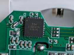
    Close-up of a circuit board with a chip labeled T34.

    Added after 7 [minutes]:

    It's not a good picture but here we can see little differences:
    Top view of a PCB with electronic components and two metal holders.

    Added after 13 [minutes]:

    Managed to open the plug again without damaging it.
    I measured 9.5uF at the cap without desoldering. Don't know if this is reliable.

    Added after 9 [minutes]:

    I do like these little contact-clamps you have. They seem to be very useful.

    One thought about your wifi problems. Antenna is connected to pin 2 only when you check the schematics design from T34.
  • #15 21039197
    p.kaczmarek2
    Moderator Smart Home
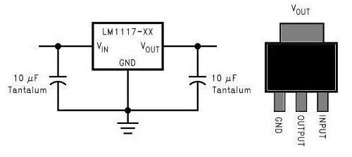
    The capacitor value at AMS117-3.3V is not critical. It seems to be usually 10uF. You can check out application schematics of AMS1117 for more info.

    Circuit diagram and package of LM1117.
    Helpful post? Buy me a coffee.
  • #16 21039554
    Raufaser
    Level 10  

    No success yet. I soldered a 5uF cap in place. I salvaged that from somewhere else.

    These are my pin settings:

    [T34/BL0937] Teardown Generic Wifi Smart Plug with Energy Measurement

    I noticed something very strange wifi-related. When I bring my plug to emergency mode and scan for wifi networks I get this:

    [T34/BL0937] Teardown Generic Wifi Smart Plug with Energy Measurement

    I reworked all pins with flux and solder. The joints look OK...

    Added after 1 [hours] 12 [minutes]:

    Screenshot showing electrical values: voltage 239.8 V, current 0.177 A, power 22.50 W, apparent power 42.66 VA, reactive power 36.25 var.

    Success :) I replaced the 5uF with a 10uF!

    Wifi is still &!"&$
  • ADVERTISEMENT
  • #17 21039782
    rufus4
    Level 10  

    Did you try already "clear all" and reflash with the BK7231flasher?
  • #18 21040011
    Raufaser
    Level 10  
    Wouldn't i have to rewire everything? No way ;)
  • #20 21040180
    p.kaczmarek2
    Moderator Smart Home
    "Clear All" and "Restore RF partition" are not recommended. The default RF partition (factory settings) are the best.

    Does your MAC end with 00 00 00 ? That could indicate that you actually already broke your RF and lost factory calibration.
    Helpful post? Buy me a coffee.
  • #21 21040846
    Raufaser
    Level 10  
    Nope. It ends in AC:DD ...

    Added after 1 [hours] 19 [minutes]:

    Hey guys! Big success 👍

    I reworked the T34 again completely. Took it off, cleaned the pads and everything (actually twice) and soldered in back in place using hot air. At the end i applied a little bit of pleasure on top. Now wifi works beautifully. And even the blinking LED when it is trying to connect to Wifi as well. I didn't even know the device had 2 LEDs :)

    And as cherry on top, today another T34 plug arrived from Aliexpress 🤣
  • #22 21041263
    p.kaczmarek2
    Moderator Smart Home
    So it was hardware issue?

    At least you didn't clear RF, because if you were to do that, then you'd actually make situation even worse.

    Hmm so T34 are getting popular?
    Helpful post? Buy me a coffee.
  • #23 21044837
    aliexpress
    Level 4  

    I just wanted to mention that I also received this very same T34 type Smart Plug.
    My strategy to get the device flashed:
    - keep the T34 on the PCB
    - use enameled copper wire to attach on the device side ("Kupferlackdraht" in German), I had one with 0.25 mm diameter. The advantage is that this wire is very thin and can fit better to pins of ICs. It also is light and quite flexible - when you move it, it does not provide high forces to the IC pins, so less chance of breaking them off, or stripping off the copper layer of the PCB. Disadvantage: To get the insulation layer off to be able to apply solder is sometimes a bit of a challenge. Then I used ordinary cables to extend these thin wires to attach to PSU and to Serial converter.
    - For P25, I soldered directly to IC pin.
    - For P26, I used the connection at the resistor
    - 3.3V and GND I attached directly to Pins 1 and 2 of AMS1117

    For flashing, I had to power cycle for like 5 times or so until the serial connection was established.
    The dump of original firmware did not contain Tuya keys, according to flasher tool. The socket was Tuya activated before.
  • Helpful post
    #24 21052214
    Raufaser
    Level 10  
    I just flashed the second T34 smart plug I got from Aliexpress. This time I did it like recommended before.
    Quote:
    - keep the T34 on the PCB
    - For P25, I soldered directly to IC pin.
    - For P26, I used the connection at the resistor
    - 3.3V and GND I attached directly to Pins 1 and 2 of AMS1117


    Nice username by the way ;)

    [T34/BL0937] Teardown Generic Wifi Smart Plug with Energy Measurement

    Please add the device to the list:
    {
      "vendor": "QNCX",
      "bDetailed": "0",
      "name": "Generic Smart Plug with Energy Measurement (T34)",
      "model": "T34 Smart Plug",
      "chip": "BK7231N",
      "board": "T34",
      "flags": "1024",
      "keywords": [
        "power metering,,",
        "smart plug",
        "bl0937"
      ],
      "pins": {
        "6": "BL0937CF;0",
        "7": "BL0937CF1;0",
        "8": "BL0937SEL;0",
        "24": "Rel;0",
        "26": "Btn;0",
        "28": "WifiLED;0"
      },
      "command": "",
      "image": "https://obrazki.elektroda.pl/4477082300_1710363453.jpg",
      "wiki": "https://www.elektroda.com/rtvforum/viewtopic.php?p=21044837"
    }
  • #25 21052473
    p.kaczmarek2
    Moderator Smart Home
    Sure, I have added this device:
    https://github.com/OpenBekenIOT/webapp/commit/dd2fe7d99e28619a41f182d488ebcf1b1c93dde4
    I also added LSPA9 mention because it looks like yet another LSPA9 version from the outside.

    However, I am not sure, should we treat T34 as a board or as a chip?
    Helpful post? Buy me a coffee.
  • #26 21052575
    rufus4
    Level 10  
    p.kaczmarek2 wrote:
    However, I am not sure, should we treat T34 as a board or as a chip?

    From the sight of an OBK-user T34 is more like an entire board. All components which are used on a board are integrated the same as on an entire board.
    On the other side physically it is a unique chip. So why not handling it as it is in real. I would go for T34 as a chip.

    Would there be any difference between this two options for dealing with it on OBK?
  • #27 21052766
    Raufaser
    Level 10  

    I would go for T34 as a board. On the Tuya developer site, it is handled as a module. Same as for example CB2S.
  • #28 21052849
    p.kaczmarek2
    Moderator Smart Home
    I think I can agree with that. So T34 will be treated as board and chip will stay as BK7231N.
    Helpful post? Buy me a coffee.
  • #29 21054371
    donotos
    Level 2  

    Hey.
    I just finished flashing my own so thanks for the help provided here.
    I wasn't able to flash by powering the T34 with the UART. Every time I disconnected 3v3 it disconnected from USB and killed the flasher app so I had to use an external PSU.

    BTW: inverting polarity did not kill the T34!

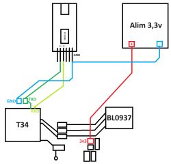
    I had some troubles wiring the chip so here is a small schematic:


    Diagram of a connection setup between T34, BL0937, and FT232RL with 3.3V power supply.

  • #30 21055174
    p.kaczmarek2
    Moderator Smart Home
    Did you invert 3.3V polarity on T34 alone or on the whole smart device board?
    Helpful post? Buy me a coffee.

Topic summary

The discussion revolves around the teardown and modification of a generic WiFi smart plug, specifically the T34 model, which features energy measurement capabilities. Users share their experiences with soldering connections for UART flashing, troubleshooting issues with the T34 chip, and the challenges faced during the process. Key points include the identification of the chip as BK7231N, the use of OpenBeken firmware, and the importance of proper pin connections for successful flashing. Users also discuss power consumption measurements and the implications of power-saving modes. The conversation highlights various techniques for soldering and the significance of component values, such as capacitors, in the device's functionality.
Summary generated by the language model.
ADVERTISEMENT