logo elektroda
logo elektroda
X
logo elektroda

[BK7231N] Teardown Action LCS Smart Plug (with Energy Meter) 3202087

mihaim1980 6720 20
ADVERTISEMENT
  • Hi!

    I've bought a new smart power socket from Action. Aparrently it's a new model that haven't been posted here. It is using CB2S module.

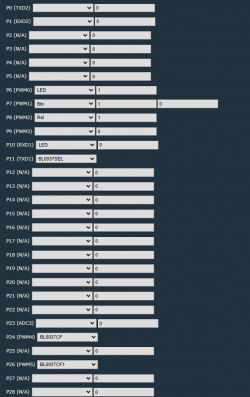
    Screenshot of pin configuration for a smart socket.
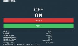
    Smart power socket user interface displaying measurement data.
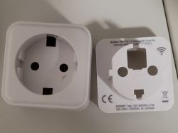
    New Action smart power socket in white color.
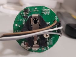
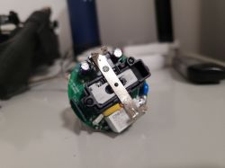
    Close-up of a circuit board inside a smart power socket with visible wires.
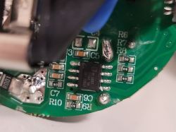
    Close-up of a circuit board featuring a BL0937 integrated circuit and various electronic components.
    Close-up of the internal components of a smart power socket showing the electronic module.
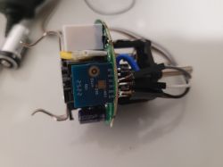
    Close-up of the interior of a smart socket with a CB2S module.
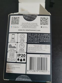
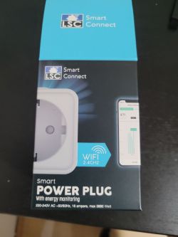
    Back of the LSC Smart Connect smart plug packaging.
    Box of LSC Smart Connect smart power plug.


    JSON config:
    Code: JSON
    Log in, to see the code


    Plaintext:
    Device configuration, as extracted from Tuya: 
    - BL0937 SEL on P11
    - Button (channel 1) on P7
    - LED (channel 1) on P6
    - BL0937 VI on P24
    - WiFi LED on P10
    - BL0937 ELE on P26
    - Relay (channel 1) on P8
    Device seems to be using CB2S module, which is using BK7231N.
    And the Tuya section starts, as usual, at 2023424

    Cool? Ranking DIY
    About Author
    mihaim1980
    Level 4  
    Offline 
    mihaim1980 wrote 18 posts with rating 5, helped 1 times. Been with us since 2023 year.
  • ADVERTISEMENT
  • Helpful post
    #2 20858024
    p.kaczmarek2
    Moderator Smart Home
    OBK config:
    Code: JSON
    Log in, to see the code


    Added after 13 [minutes]:

    Added, thank you:
    https://github.com/OpenBekenIOT/webapp/commit/6b2b0c0fd57f1b99a3bbf2a88d073ffe651e46c4
    Helpful post? Buy me a coffee.
  • ADVERTISEMENT
  • #3 20867538
    Dobie01
    Level 8  

    Hi,
    Thanks for the info. How did you open it without breaking the housing?

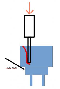
    Ok, found it: The hooks that hold it together are in the corners. So you have to press the edge on the side of a table at a 45° angle and then push on the left or right ground surface with a screwdriver.

    Schematic drawing showing how to remove a device cover using a table edge and screwdriver.
  • #4 20867542
    mihaim1980
    Level 4  

    In each corner on the back, there is a clip. I used a slim metal blade to force it a bit.
  • #5 20872104
    aldialbrecht2
    Level 4  

    Hello everyone,

    I also received the sockets today. Unfortunately, it is not possible for me to flash these with the Tuya Cloudcutter OTA. Which profile should you choose? The Tuya firmware is V1.1.17.

    Thanks in advance!
  • #6 20872184
    Dobie01
    Level 8  

    AFAIK, it is not in the profiles yet. I simply entered the settings listed in the JSON.
    In "BK7231 Easy UART Flasher," I used the button "change obk settings for flash write" and edited the details before flashing,
    switched "Automatically extract Tuya..." and
    "Do firmware backup" off
    and then it worked.
    I struggled a bit to get the flash process going under Linux. When you reset by "power off," Linux loses the UART port setting, and the CEN input somehow didn't do what I expect. For me, it is still unclear how to enter flash mode - it worked at one point, but I cannot say what I did.
  • #7 20872214
    p.kaczmarek2
    Moderator Smart Home
    Dobie01 wrote:
    Afaik it is not in the profiles yet. I simply entered the settings listed in the json.

    If you are referring to OBK profile, it seems to be here:
    Screenshot of an electronic devices database.

    Dobie01 wrote:
    When you reset by "power off" Linux looses the UART port setting

    Have you watched our tutorial videos? We have videos one per each device type showing the process:
    https://www.youtube.com/@elektrodacom
    By "power off", we mean that you need to disconnect you 3.3V from WiFi module (or 12V from LED strip). This will not work if you disconnect from USB to UART converter, because then COM port will diseappear.
    Also make sure to use good quality power supply, because in some rare cases, if you power device from 5V (to use onboard LDO regulator to get 3.3V), and you reset by disconnecting that 5V wire from USB, this may still cause UART port diseappear because you overload the USB port with too large inrush current
    Helpful post? Buy me a coffee.
  • ADVERTISEMENT
  • #8 20872260
    aldialbrecht2
    Level 4  

    Dobie01 wrote:
    AFAIK, it is not in the profiles yet. I simply entered the settings listed in the JSON. In "BK7231 Easy UART Flasher," I used the button "change obk settings for flash write" and edited the details before flashing,


    Thanks for the information. It's a shame that it's currently not possible to flash these sockets OTA. Unfortunately, I don't have the time for soldering work at the moment. I tried to create a custom profile in the tuya cloud cutter using the JSON data. Unfortunately, I failed.
  • #9 20905019
    setheal74
    Level 1  
    Don't lose too much time trying. This firmware version 1.1.17 is using the SDK 2.3.3 that is patched. Cloud cutter will not work with it.
  • ADVERTISEMENT
  • #10 20905026
    p.kaczmarek2
    Moderator Smart Home
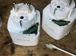
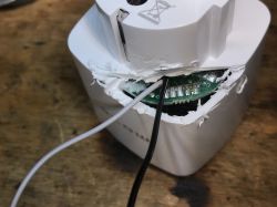
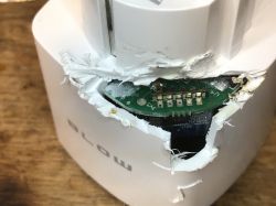
    It's easy to flash with wires, even if socket is hard to open. Here's how I handled one like that:
    Two damaged smart sockets with exposed internal electronics. Close-up of a damaged plastic device with visible wires and a circuit board. Close-up of a white plastic casing with damage exposing a green electronic circuit board.
    It's just import to secure the hole later.
    Helpful post? Buy me a coffee.
  • #11 20905481
    aldialbrecht2
    Level 4  
    setheal74 wrote:
    Don't lose too much time trying. This firmware version 1.1.17 is using the SDK 2.3.3 that is patched. Cloud cutter will not work with it.

    Thanks for the hint. I honestly didn't realize that.

    p.kaczmarek2 wrote:
    It's easy to flash with wires, even if socket is hard to open. Here's how I handled one like that:


    Fortunately, the LSC sockets are not glued and can be opened easily. Do you have a tutorial for flashing using a USB to TTL serial adapter? Thanks in advance!
  • #12 20905515
    p.kaczmarek2
    Moderator Smart Home
    We have many tutorials for that, here are two examples, N platform:


    T platform:


    Helpful post? Buy me a coffee.
  • #13 20914389
    aldialbrecht2
    Level 4  
    Hello everyone,

    today I successfully flashed said sockets to openbk using a USB to TTL converter.

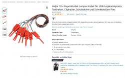
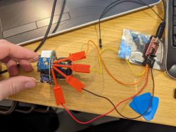
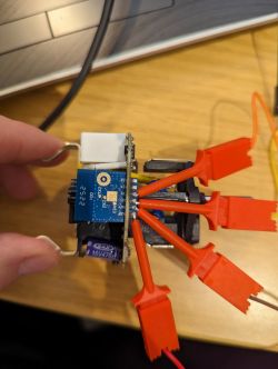
    The whole thing worked without soldering using jumper cables and test hooks. If you are interested, here is the link and two more pictures:
    Close-up of a Haljia DuPont cable set with test hooks, available on Amazon.
    https://amzn.eu/d/c8j3XUQ

    A hand holding an electronic setup with cables and test hooks connected to a USB to TTL converter on a wooden desk next to a laptop. Close-up of a hand holding an electronic board with connected red wires and test hooks.
  • #14 20915418
    dingsundbums
    Level 5  
    Great Tip !
    Just ordered those too !

    Hinzugefügt nach 4 [Minuten]:

    Just managed yesterday to also flash one by myself.
    But I am personally using ltchiptool on debian cli myself to flash.
    Worked perfect.

    Sensors have to be created a bit different than the profile suggest since the Voltage divider is wrong set and the second led is not created out of the dump.

    
    sensor:
      - platform: hlw8012
        model: BL0937
        cf_pin:
          number: P26
          inverted: true
        cf1_pin:
          number: P24
          inverted: true
        sel_pin:
          number: P11
          inverted: true
        current:
          name: Current
        voltage:
          name: Voltage
        power:
          name: Power
        energy:
          name: Energy
        #voltage_divider: 1600
        voltage_divider: 800
        current_resistor: 0.001 ohm
        update_interval: 6s


    and

    
    light:
      - platform: status_led
        id: blue_led
        pin: P10
        internal: True
      - platform: status_led
        id: red_led
        pin: P6
        internal: True
    
  • #15 20915514
    p.kaczmarek2
    Moderator Smart Home
    dingsundbums wrote:

    Sensors have to be created a bit different than the profile suggest since the Voltage divider is wrong set and the second led is not created out of the dump.

    The simplest way to get it automatically configured is to use our OBK Web App config extraction:


    Thanks to this, you can get GPIO config directly from Tuya partition. It's always better than guessing.

    Anyway, it's good to hear you got that working in your way.
    Helpful post? Buy me a coffee.
  • #16 20915526
    dingsundbums
    Level 5  
    Did it with a dump to get the pinout. Worked too.
    As said: only Voltage divider was wrong.
  • #17 21029538
    ElektroTechnikus
    Level 8  
    I have just spontaneously registered here to add some more information. Maybe it will help some successors. Thanks also for the help I found here.

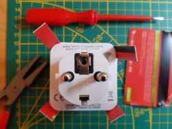
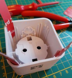
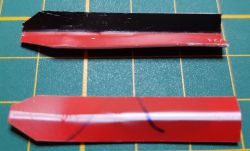
    "Action" in Germany still has some of these sockets on sale and as they are the cheapest with energy metering I could find, I thought I'd give them a try. Disassembly also seemed to be simple...

    However, I didn't find it quite so easy and "carved" four wedges from a credit card to release the tabs in the corners of the housing. I had to use another credit card and a pair of pliers to get them inserted. In the pictures you can see where they finally went in with some difficulty and a lot of wiggeling.

    Electrical socket with adapter and credit card wedges, tools on a measuring mat background. Close-up of an opened socket with credit cards inserted into the casing. Two wedges made from credit cards on a green cutting mat.

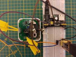
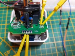
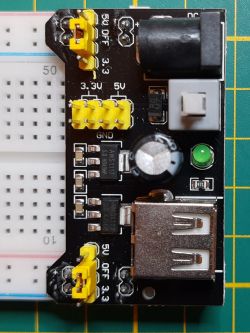
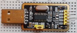
    In fact, the power supply from the CH340 adapter was not sufficient, but an existing breadboard power supply solved the problem quite easily, especially as it has its own switch. I also followed the tip with the mini terminals. Again, hopefully the photos show enough detail. The power was injected at the terminals of the 3.3 volts filter capacitor.

    (I did the backup and flashing in two separate steps.)


    Close-up of an electronic circuit with a socket and adapter on a breadboard. The image shows a dismantled electrical socket with an exposed circuit board and attached measurement wires. Close-up of a prototype development board with 3.3V and 5V markings and yellow jumpers. USB to TTL adapter with an integrated circuit on a breadboard
  • #18 21041242
    hrijneke
    Level 6  
    Hey! so i flashed the chip and all well. But when i calibrate the power, it stays on 2.5watt even the attached appliance is 100% off? Did i do something wrong or is the onboard powermeter not very reliable? I did an athom plug the same way and no problems there...
  • #19 21041264
    p.kaczmarek2
    Moderator Smart Home
    Apart from the 2.5W issue, which seems similiar to the problem I read in this topic:
    https://www.elektroda.com/rtvforum/topic4047633.html
    do everything else works correctly? Are 100W, 200W, etc, loads correctly measured?
    Helpful post? Buy me a coffee.
  • #20 21041328
    hrijneke
    Level 6  
    thank you for the quick reply. Ill have a new go at calibrating (although i did it the same way as the athom) and read the given topic.
    once i know more ill report bank!
  • #21 21544388
    4N6nerd
    Level 2  
    I had an old LSC smart plug without the energy monitor and with the strange labeled CB2S board (the one with the T cpu instead of the N version)
    Anyway.... I flashed it using my DOIT ESP32 devkit V1. Or actualy only the CP2102 USB-serial chip which is on that board. The power supply on that board can power the ESP32 so it should be, and is, ably to power a CB2S board.

    So i connected it as follows:
    3V3 to 3V3
    GND to GND
    TX to TX *
    RX to RX *
    EN to GND **


    * YES this is right. TX to TX and RX to RX.
    The TX/RX lables on the ESP32 devboard are labled from the ESP perspective. So from the CP2102 perspective it is the other way around.
    So the label TX on the board is the TX of the ESP and is connected to the RX of the CP2102

    ** This is the main trick in this method. EN is the "chip enable" pin of the ESP32.
    Pulling EN to GND makes the ESP32 inactive. Effectivaly leaving you with just the CP2102 USB to serial converter and a powerfull enough 3V3 powersupply.


    I bought myself a new LSC powerplug yesterday. It turns out to be the 3202087 from Action. Opened it with just two small screwdrivers and some plastic strips. The plug itself is made of soft plastic which makes it very forgiving with regard to eventual damage. I love them.

Topic summary

The discussion revolves around the teardown and flashing of the Action LCS Smart Plug (model 3202087) equipped with the BK7231N chip and CB2S module. Users share insights on disassembling the device, with tips on locating and releasing the housing clips. Several participants report challenges in flashing the device using Tuya Cloudcutter OTA due to firmware limitations (version 1.1.17) and suggest alternative methods, including using a USB to TTL converter and jumper cables. Calibration issues with the onboard power meter are also discussed, with users experiencing inaccurate readings when appliances are off. The community provides various configurations and troubleshooting advice, including JSON settings for flashing and sensor calibration.
Summary generated by the language model.
ADVERTISEMENT