FAQ
TL;DR: 1x10m RGBIC+CCT LSC 3202086 runs BK7231N; “Currently you also need to manually configure WS2812B-style LEDs.” Flash OpenBeken, set WS2812/PixelAnim, and map CW PWM pins per revision. [Elektroda, p.kaczmarek2, post #21101486]
Why it matters: This helps DIYers flashing OBK/ESPHome go cloud-free, fix “no light” issues, and avoid revision-specific pin traps.
Quick Facts
- SoC/module: BK7231N (CBU). OpenBeken works; RGBIC addressable plus CW PWM channels; manual WS2812 setup may be needed. [Elektroda, p.kaczmarek2, post #21101486]
- Rev 3202086.1: MOSI P16 drives RGB data; typical LedNum is 40. [Elektroda, divadiow, post #21337134]
- Rev 3202086.2: CW=P9, WW=P24, power pin=P6; button=P7; IR=P26; RGB data=P16 (ESPHome example). [Elektroda, xpeng, post #21358222]
- Rev 3202086.1: CW=P6, WW=P24, power pin=P22; button=P20; IR=P26; RGB data=P16 (ESPHome example). [Elektroda, matiserv4, post #21362240]
- PWM frequency: 1000 Hz; IR receiver on P26 (from Tuya extract). [Elektroda, divadiow, post #21337134]
What is the LSC 3202086 and can I flash OpenBeken for cloud-free control?
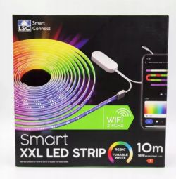
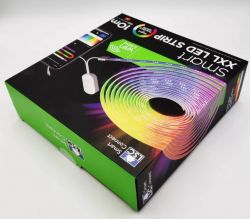
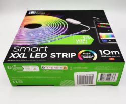
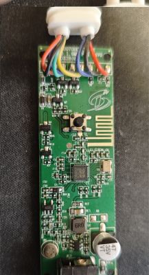
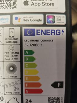
It’s an LSC Smart Led Strip 1x10m RGBIC + CCT using a BK7231N (CBU) Wi-Fi SoC. OpenBeken supports this chip. The strip has individually addressable RGB LEDs plus separate PWM channels for white. WS2812-style LEDs require manual setup in OBK’s PixelAnim panel. [Elektroda, p.kaczmarek2, post #21101486]
Which pin drives the addressable RGB LEDs on this controller?
P16 (hardware SPI MOSI) drives the per-pixel RGB data. As the maintainer notes, “It’s always P16, hardware SPI output.” Use this pin with SM16703P/WS2812 drivers in OpenBeken or beken_spi_led_strip in ESPHome. [Elektroda, p.kaczmarek2, post #21336982]
How many addressable LEDs should I configure?
Typical configuration for revision 3202086.1 sets LedNum to 40. If your effects look truncated or mirrored, adjust this count to match your strip length. The Tuya extract shows LedNum: 40 for that hardware. [Elektroda, divadiow, post #21337134]
What PWM frequency should I use for the CW/WW channels?
Use 1000 Hz PWM for the white channels. This value comes from the device’s Tuya configuration and works well with BK7231N-driven drivers. [Elektroda, divadiow, post #21337134]
What pins and ESPHome mapping work for LSC 3202086.1?
Use P16 for RGB data, CW on P6, WW on P24, and power/control on P22. IR receiver is P26 and the on-board button is P20. Example ESPHome sets num_leds: 40 and beken_spi_led_strip on P16. [Elektroda, matiserv4, post #21362240]
What pins and ESPHome mapping work for LSC 3202086.2?
Use P16 for RGB data, CW on P9, WW on P24, and power/control on P6. IR receiver is P26 and the button is P7. Example ESPHome uses num_leds: 40 with beken_spi_led_strip and power_supply on P6. [Elektroda, xpeng, post #21358222]
How do I enable RGB with PixelAnim in OpenBeken?
Run these commands (e.g., in autoexec):
- startDriver SM16703P
- SM16703P_Init 16
- startDriver PixelAnim
Then set pixel count and toggle power in the UI. This initializes WS2812 via P16. [Elektroda, Dratii, post #21337021]
I flashed successfully, but nothing lights. How do I fix it?
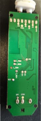
Verify 24 V is present on the strip rails. Many boards gate LED power with a transistor, enabled by a control pin. Use GPIODoctor to set suspected PWM/control pins high and watch for 24 V at the strip and any glow. Then configure PixelAnim on P16 to confirm RGB output. [Elektroda, p.kaczmarek2, post #21336982]
What does the power/control pin do on these boards?
It enables the LED power path, often gating 24 V to the strip. Some designs also modulate brightness there. If LEDs stay dark, assert this pin before driving CW/WW or RGB. The control sits between 24 V input and LED output via a transistor. [Elektroda, p.kaczmarek2, post #21336982]
How can I find the correct CW/WW pins if they’re unknown?
Open GPIODoctor and toggle each PWM-capable pin while measuring LED power. “Try playing with GPIO Doctor on PWM pins.” Note which pin brings up 24 V or lights cold/warm channels, then map those to CW/WW. [Elektroda, p.kaczmarek2, post #21327629]
Does OpenBeken now support combined RGBIC + CW?
Development progressed: “RGB IC + CW PWMs” was tested and working in the simulator. If your build predates this, use manual PixelAnim plus PWM. Update to a recent OBK release for integrated control. [Elektroda, p.kaczmarek2, post #21101992]
I lost power from 24 V input after tinkering. What should I check?
Inspect for mechanical damage and trace voltage from the 24 V jack through the step-down converter. Measure where voltage stops. If the regulator or fuse path is open, repair it before further tests. Provide clear board photos to aid diagnosis. [Elektroda, p.kaczmarek2, post #21327640]
BK7231N runs on 3.3 V but the board stays dark on 24 V—what does this indicate?
This points to a failed 24 V power path or regulator stage. One user saw 24 V at input, yet the controller board was unpowered, while the BK7231N worked when powered directly. Inspect the input path and regulator. [Elektroda, snakesrules94, post #21327635]
Is there a starter OpenBeken template I can import?
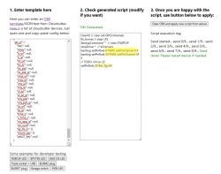
Yes. A base OBK template was shared with button on P7 and PWM on P9 (CW) and P24 (WW). WS2812 requires manual configuration via PixelAnim. Use it as a starting point and adjust for your revision. [Elektroda, p.kaczmarek2, post #21101486]
