logo elektroda
logo elektroda
X
logo elektroda

Converting LSC 3203632.1 5 Meters LED Strip RGB/C + CCT/C to OpenBeken

snakesrules94 1899 19
ADVERTISEMENT
  • Helpful post
    #1 21332211
    snakesrules94
    Level 8  
    In addition to the topic Converting LSC 3203632 Smart LED Strip to OpenBeken: Challenges with BK7231N Flashing , here's my attempt with the version 3203632.1 which seems different .

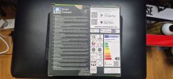
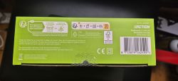
    To start with some pictures :
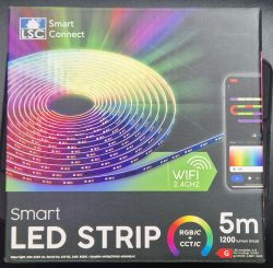
    LSC Smart LED Strip packaging with rainbow graphics.Back of the LSC Smart Connect box with QR codes and technical information.Green packaging with recycling information and FSC certification.

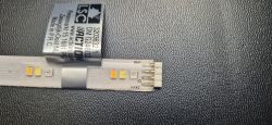
    There are 25 parts like this one to achieve the 5M strip :
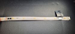
    Smart LSC 3203632 LED strip on a black background.
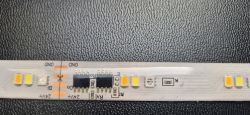
    Section of LSC LED strip with code 3203632.1.Section of LED strip with visible diodes and components.

    The 2 CI's on strip are totally black, no writing, no refs.

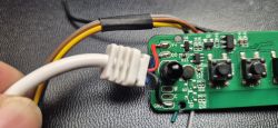
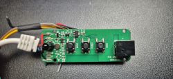
    And finally the board itself : 3 buttons, IR receiver, 24V power
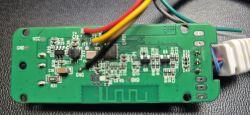
    Circuit board with wires and electronic components. Close-up of an electronic board with three buttons and an IR receiver, along with connected wires. Circuit board with three buttons and colored wires.

    As we can see, everything is driver by Do output. Cold/warm channels are not used .

    The backup from original BK7231N fw is ok but no way to retrieve the conf : "Failed to extract keys" with BK7231Flasher

    readResult...-10-09.zip Download (1.46 MB)Points: 1 for user

    after investigations, here are my results :

    PWM on P6 to control light
    REL on P8 to ON/OFF the 24V on the strip
    Buttons on P9 / P24 / P28
    and SM16703 on P16

    Right now, i can on/off the strip , Brightness is ok , IR Receiver ok, colors are ok ( BRG order )
    Buttons are working but each one acts as a toggle switch for the strip in the current conf.
    I didn't find yet how to control RGB from WHITE cool/warm are there is only one channel wired to the strip.

    "pins": {
        "6": "PWM;4",
        "8": "Rel;20",
        "9": "Btn;3",
        "16": "SM16703P_DIN;0",
        "24": "Btn;4",
        "26": "IRRecv;0",
        "28": "Btn;50"
      },


    Regards.
  • ADVERTISEMENT
  • #2 21333653
    p.kaczmarek2
    Moderator Smart Home
    Was Cool/Warm color working with Tuya app?

    So there is only VDD, GND and DATA going to strip? I see W (warm) and C (cool) pads not soldered...
    Helpful post? Buy me a coffee.
  • #3 21334397
    snakesrules94
    Level 8  
    Hello,
    yes, white cool/warm was ok within tuya app. You could choose either color and select, or white and select cool/warm.
    Indeed, only gnd/gnd and Do line between the controller and the strip, C/W pads on the PCB are not used.

    Regards.
  • #4 21338334
    snakesrules94
    Level 8  
    Hello,
    I've reflashed original FW this morning to check :

    Close-up of an LED strip with three diodes and power markings.

    When using RGB mode, only led 1 is used
    When using cool white mode, only led 2 is used
    When using warm white mode, only led 3 is used
    When using other white mode, leds 1 & 2 are used

    24V is always present when using the strip.

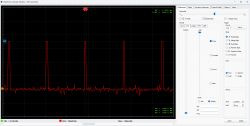
    I have a very basic Gabtronic Xscope on the computer but not sure what to check as there is only one output on the PCB and every action on the remote seems the same on the scope screen .

    Screenshot of the Gabotronics Xscope interface showing a signal graph.
  • Helpful post
    #5 21338404
    divadiow
    Level 34  
    I appreciate this isn't a direct help, but here's a bit more info. the storage area in that firmware contains the following after pairing with the Tuya app, when it pulls more information down. It does not contain any pin data, which from previous experience and what others have said, means the pin mappings are hardcoded into the firmware.

    Code: JSON
    Log in, to see the code


    just more info rather than a help
  • #6 21338479
    snakesrules94
    Level 8  
    I'm not a signal analysis expert, but could it be possible that the frequency change to drive RGB or white part on the same pin? It could make sense with the 2 IC on the strip, one for each "color"?

    From what I can monitor, I sometimes see some frequencies at 400Hz, sometimes 533Hz and sometimes 800Hz, but as told before, I only have basic equipment and not sure at all about the readings.
  • ADVERTISEMENT
  • #7 21344971
    twoenter
    Level 4  
    snakesrules94 wrote:
    I'm not a signal analysis expert, but could it be possible that the frequency change to drive RGB or white part on the same pin? It could make sense with the 2 IC on the strip, one for each "color"?

    From what I can monitor, I sometimes see some frequencies at 400Hz, sometimes 533Hz and sometimes 800Hz, but as told before, I only have basic equipment and not sure at all about the readings.


    Yesterday I've tried to make the strip work with WLED, without the tuya controller. Just the strip connected to a ESP32 with WLED firmware. With some settings the strip lit up when I connected it, but none of the possible settings led to a fully working addressable ledstrip. Still I want to connect it to Home Assistant with addressable options like in WLED.

    After this I tried flashing the same esp32 with esphome. I used the following config:
    
    spi:
      mosi_pin: 16
      clk_pin: 18
    
    light:
      - platform: spi_led_strip
        num_leds: 3
        id: rgb_led
        name: "RGB LED Strip"
        data_rate: 1MHz


    It seemed to be working but after giving a command the strip lighted up in the requested color and I think the esp32 blew up and is not accesible anymore.

    For now I've connected it to the official Tuya integration with the original firmware of the controller on it. But there are no options for segments/partitions...

    What I understand is that the device cloudcuttable is via cloudcutter. There is no esphome yaml available yet. So I searched further, I came up to this page: https://esphome.io/components/light/beken_spi_led_strip.html and make separate segments with https://esphome.io/components/light/partition.html

    In the list with supported chips is the SM16703. But P16 must be available on the chip. My question: is P16 available on the chip, and maybe you can test it by flashing esphome to it? If P16 is not available, maybe spi_led_strip may work? I can test it also by myself but I want to have the possibility to revert back to original firmware. Is that possible with you attached file in the previous post?
  • ADVERTISEMENT
  • #10 21345443
    divadiow
    Level 34  
    oh. yes. it's what looks like a discussion about the same LED strip in the WLED Discord
  • #11 21345456
    snakesrules94
    Level 8  
    I have this message with the link

    Graphic displaying the message NO TEXT CHANNELS with additional information about the lack of access to text channels on the server.
  • #12 21345460
    divadiow
    Level 34  
    what if you join the WLED Discord first? https://discord.com/invite/e2NW9hwPeV

    Added after 3 [minutes]:

    there's not a lot to see though. the conclusion was that WLED didn't support whatever it is. There was mention of WS2805 strips supporting two white channels but this mode didnt work either in WLED.
  • #13 21345792
    twoenter
    Level 4  
    After rereading the whole topic I think the esphome approach will work because @snakesrules94 said there is a SM16703 on pin 16. I will try cloudcutter and flash it to esphome with my config above
  • #15 21348244
    twoenter
    Level 4  
    What profile did you use to cloudcut the led strip @snakesrules94? I have bk7231n with version 1.0.2. All of the profiles I tried are not working.
  • #16 21348401
    snakesrules94
    Level 8  
    >>21348244
    Hello, I didn't use cloudcutter to flash as the BK is directly accessible and flashable by UART.
  • #17 21355395
    User0815
    Level 5  
    Hallo,

    meine Frage ist, ob Sie es schon geschafft haben, die RGB-Farben passend über die autoexec.bat zuzuordnen und ob Sie sie veröffentlichen könnten.
  • ADVERTISEMENT
  • #19 21360449
    twoenter
    Level 4  
    Now I am soldering the strip in parts with some lan cables between it. I'm facing some issues with broken strip parts. Some parts are working but uncontrollable, with brightness of all LEDs 100%, others stay always on if 24v is supplied. Don't know the reason for this.

    On the chip I can see the chip number: gzx16703 Damaged LED strip with visible components and chip gzx16703.

Topic summary

The discussion revolves around converting the LSC 3203632.1 RGB/C + CCT/C LED strip to work with OpenBeken firmware. Users share their experiences with flashing the BK7231N chip, noting challenges with the LED strip's functionality when interfaced with various firmware, including Tuya, WLED, and ESPHome. Key observations include the strip's operation in different color modes, the presence of unutilized pads on the PCB, and the need for specific configurations to achieve full control over the addressable LEDs. Some users report successful flashing and integration with Home Assistant, while others face issues with unresponsive or malfunctioning LED segments. The conversation also touches on the technical aspects of signal frequencies and pin mappings related to the LED control.
Summary generated by the language model.
ADVERTISEMENT