 .
.
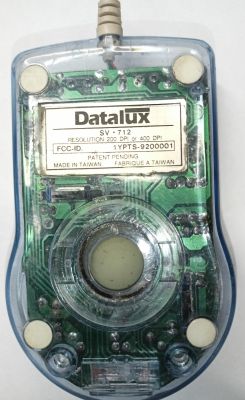
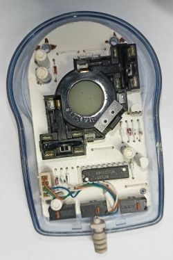
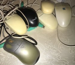
I will present here the insides of several old computer mice. Some of these mice are only two-button and do not even have a wheel. Here we will see how they are built and what circuits they are based on, we will also look at their communication protocol. What does the ball mouse look like inside? Let's find out.
Trekker mouse .
We start with a mouse without a wheel. Personally I don't remember ever having one, was it even possible to work on this? What were those times like? That's all I can find out from your comments.
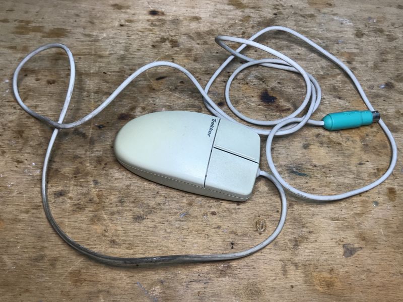
Trekker Two Button Mouse 2.0A PS/2 Compatible
PN X04-81530 90318-OEM-
5V 15mA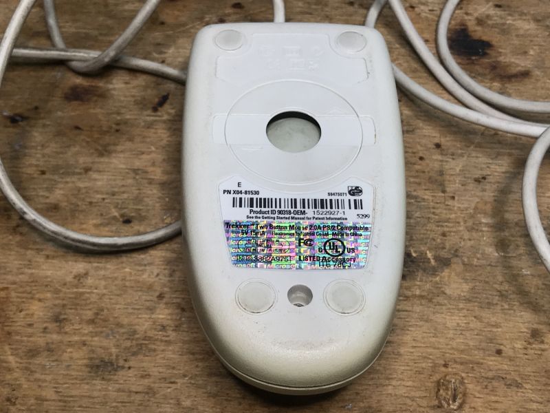 .
.
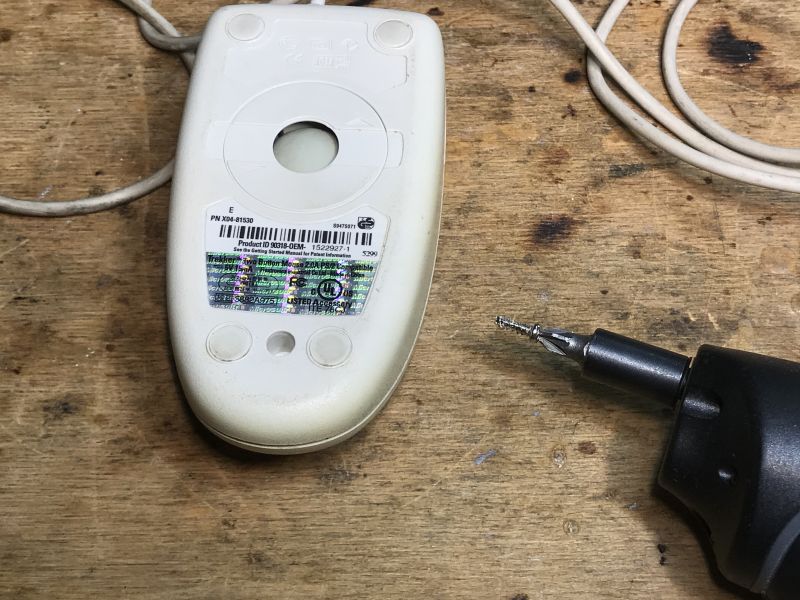
Unscrew one screw and look inside:
 .
.
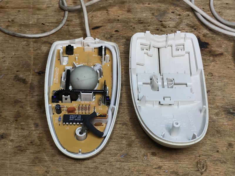
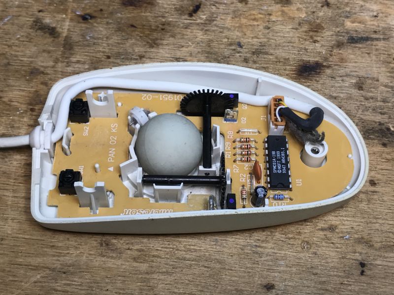
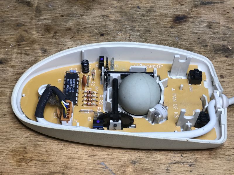
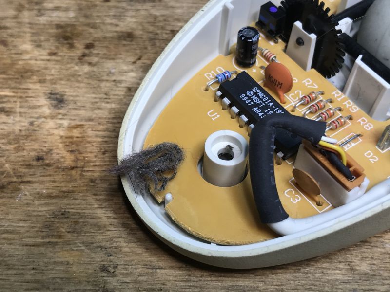
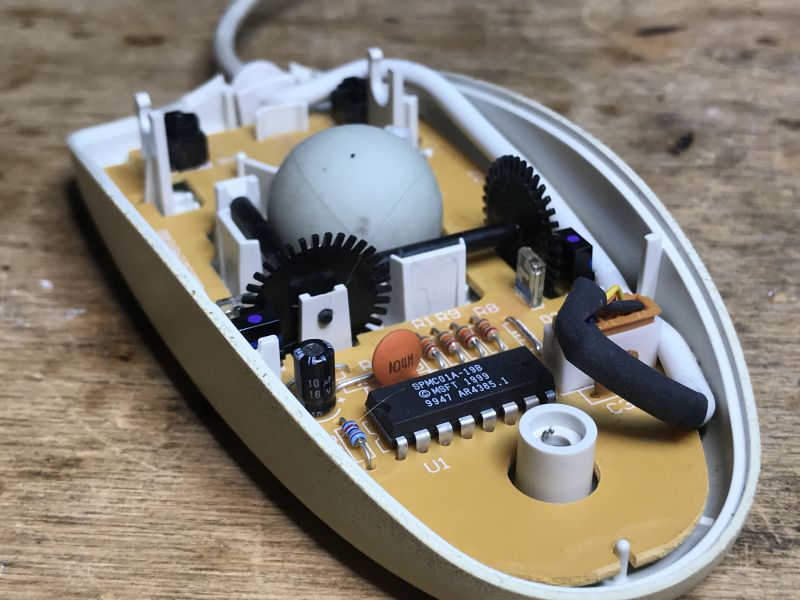
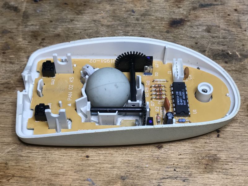
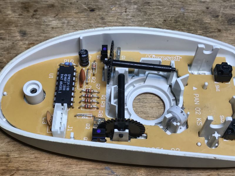
The mouse is based on the SPMC01A-19B. In the centres you can see two buttons (left and right) and two diode-phototransistor pairs, one each for the X and Y axis.
 .
.
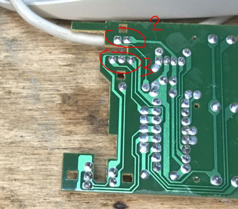
These teeth, due to the rotation of the ball, cover and expose the diode and the phototransistor collects the pulses and determines the movement on this basis. But we still need to know which way the movement is, for this reason two phototransistors are needed per axis. Here, by the way, you can see that the diode has two legs and the receiver has three:
 .
.
A similar concept with encoders is used in printers and I discussed this in more detail in the printer topic:
Teardown of the HP Deskjet D1360 printer and an example of using its parts with Arduino .
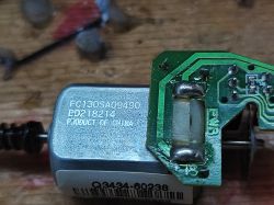
The same mechanism is also, for example, with the scanner motor from the printer, a DC motor, as manufacturers do not want to use stepper motors there as a cost-saving measure:
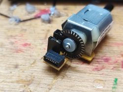
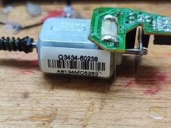 .
.
Anyway, see to the mentioned topic , there I implement support for this in the Arduino.
 .
.
Let's get the ball rolling:
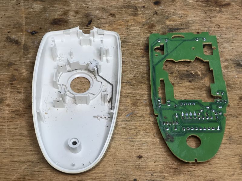
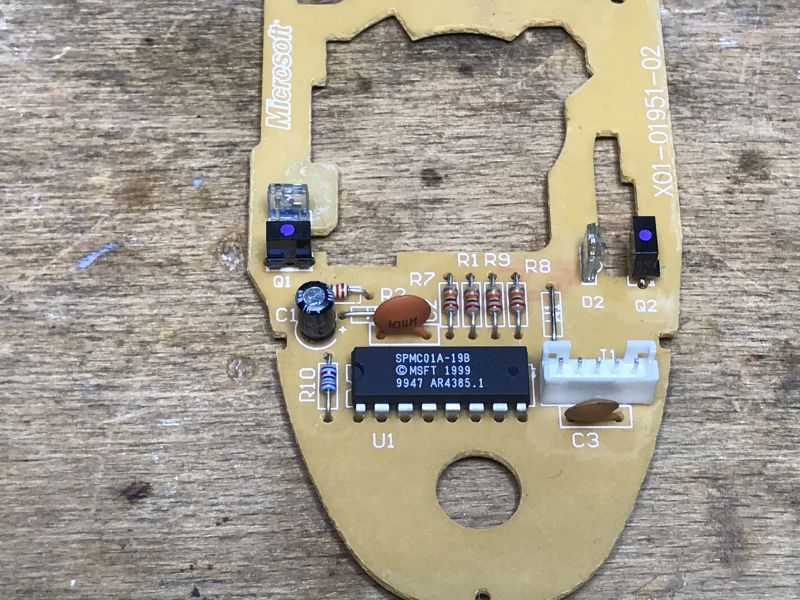
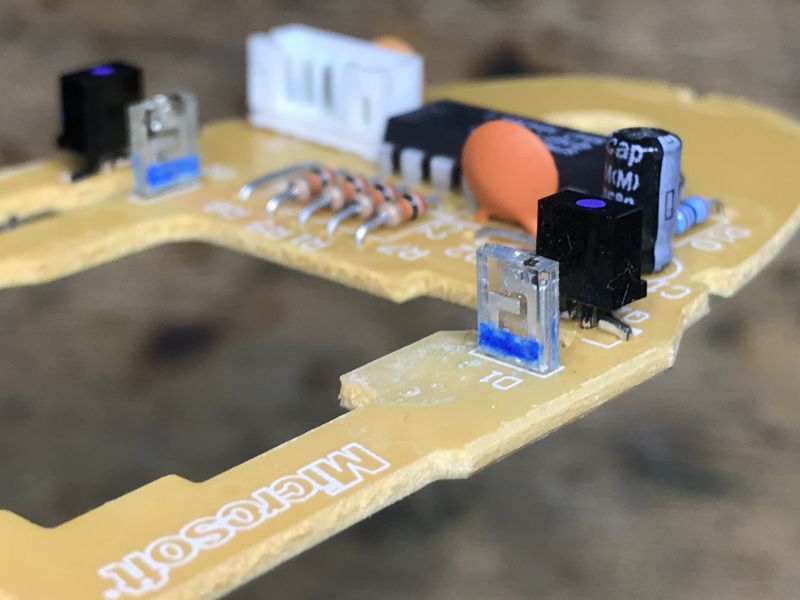
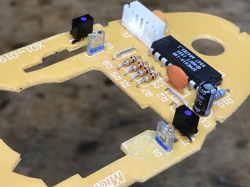

Trekker mouse with wheel .
The second mouse is also a Trekker, this time 3.0A, interestingly here at 5V and 20mA current rather than 15mA. Is this because there is a wheel here too?
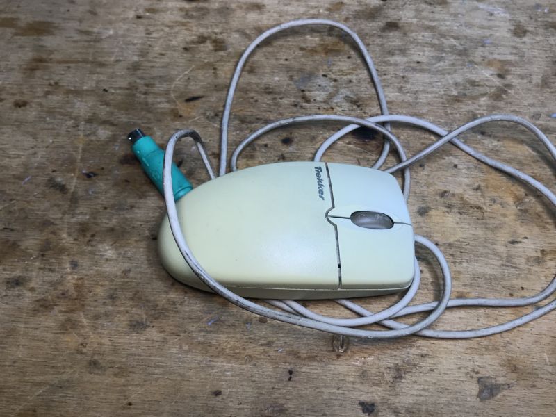 .
.
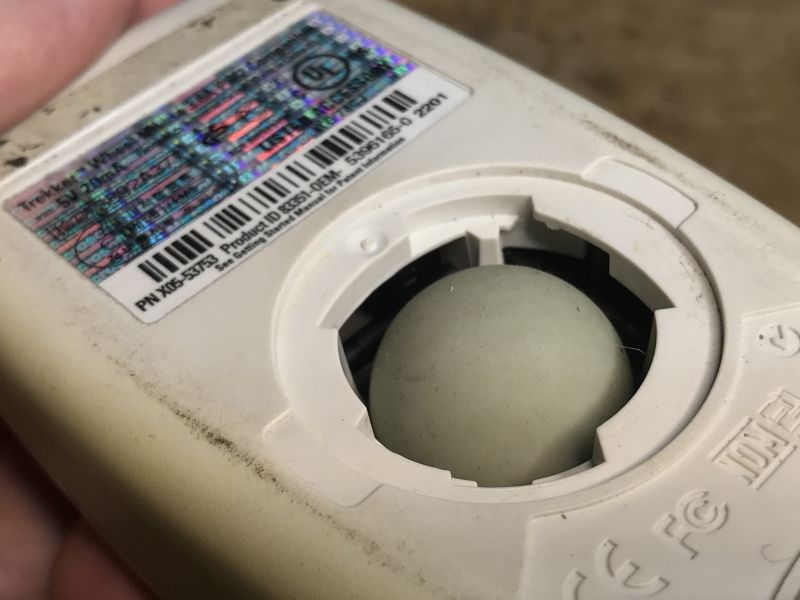
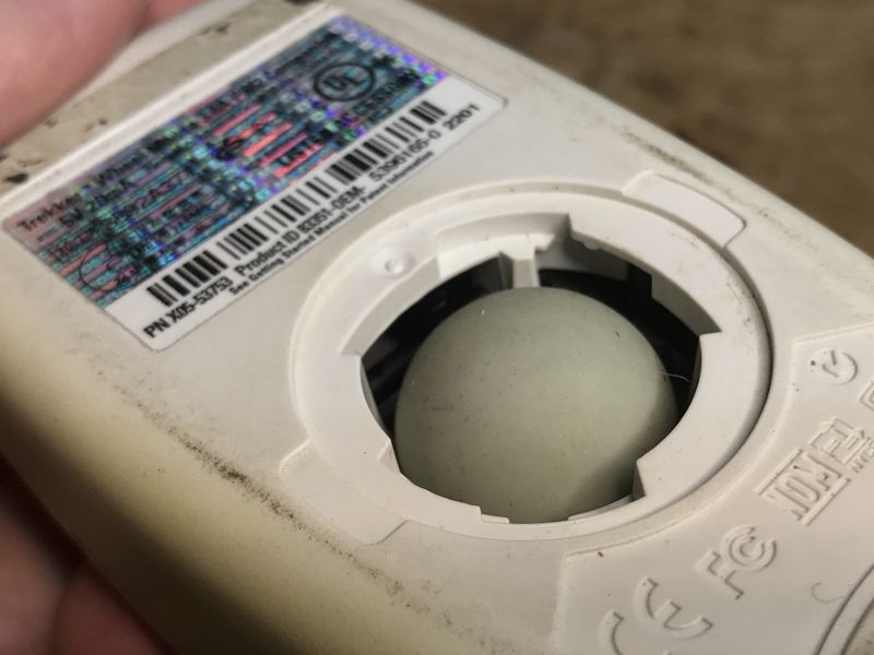
PN X05-53753 Product ID 83351-OEM-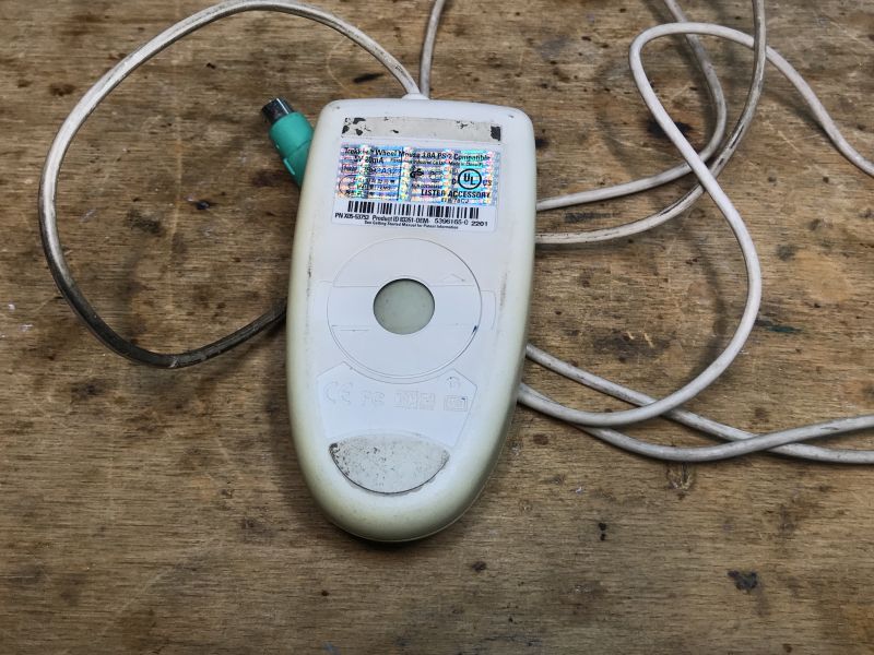 .
.
The screw is behind the ball:
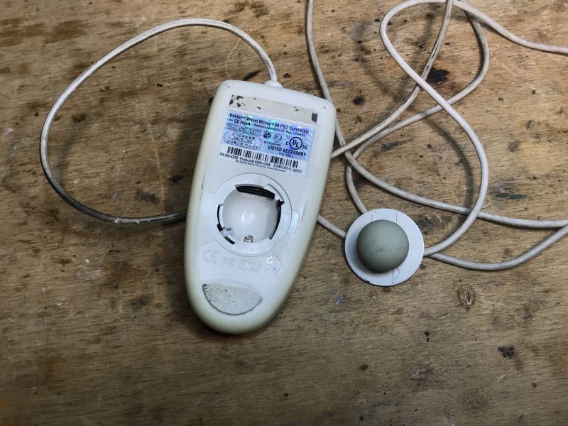
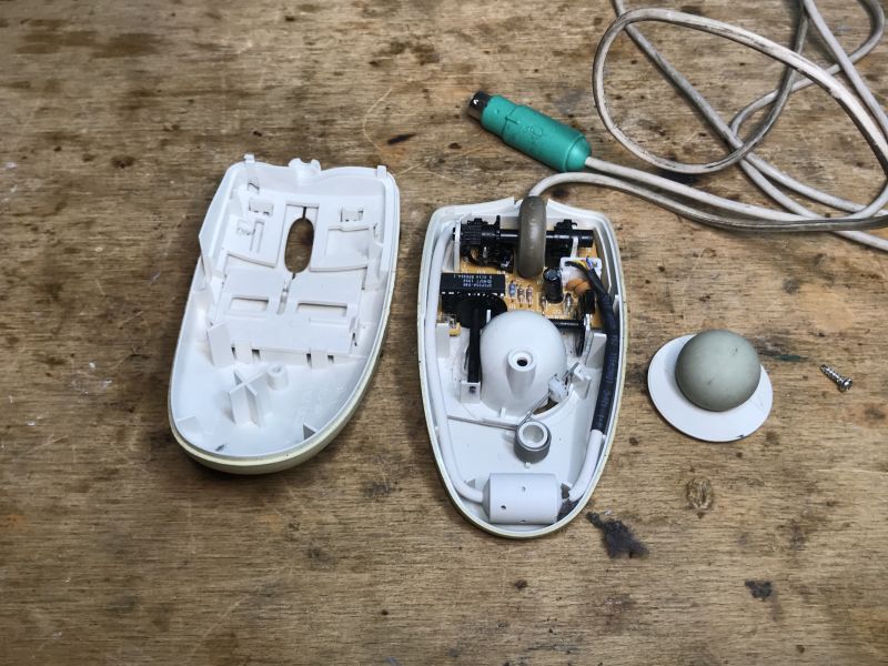 .
.
Here we have two additions - a third axis (wheel) and a third button.
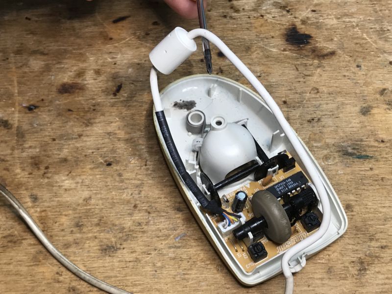
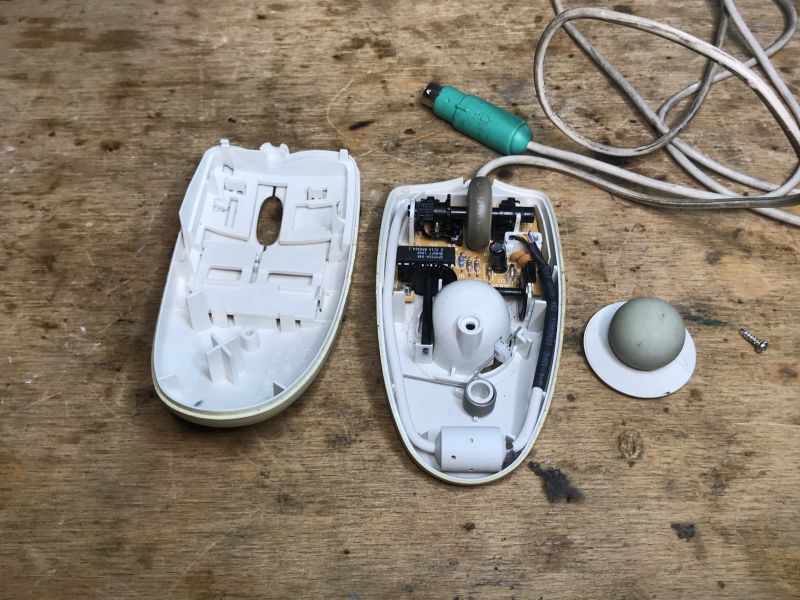
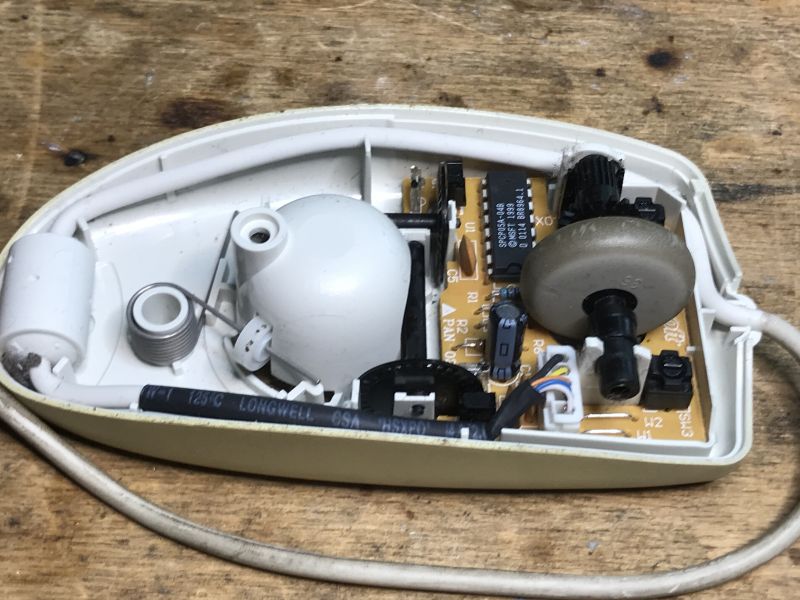 .
.
But the third axis is realised in the same way as the first two:
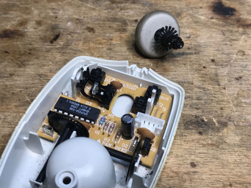 .
.
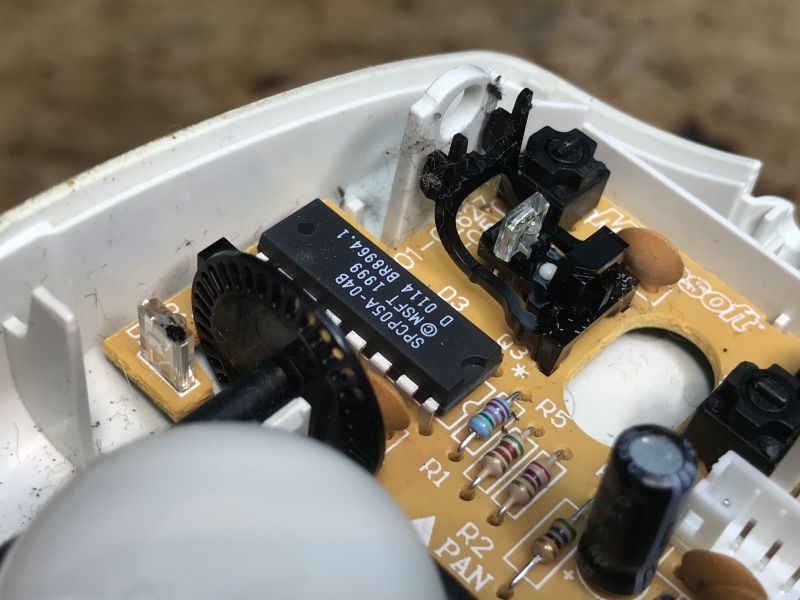
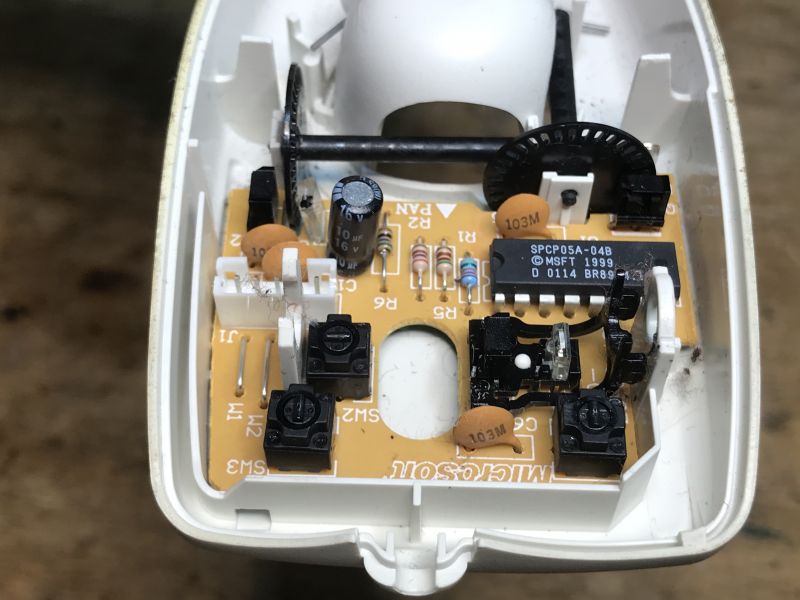
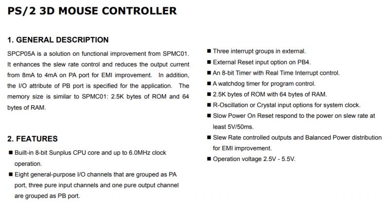
The controller is the SPCP05A-04B:
 .
.
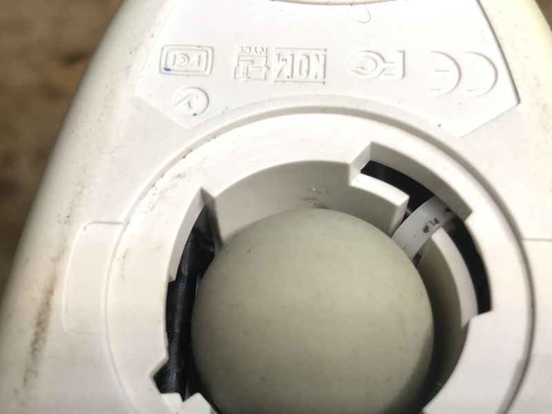
Ball attachment:
 .
.
It is interesting to note that the SPCP05A is programmable:
 .
.
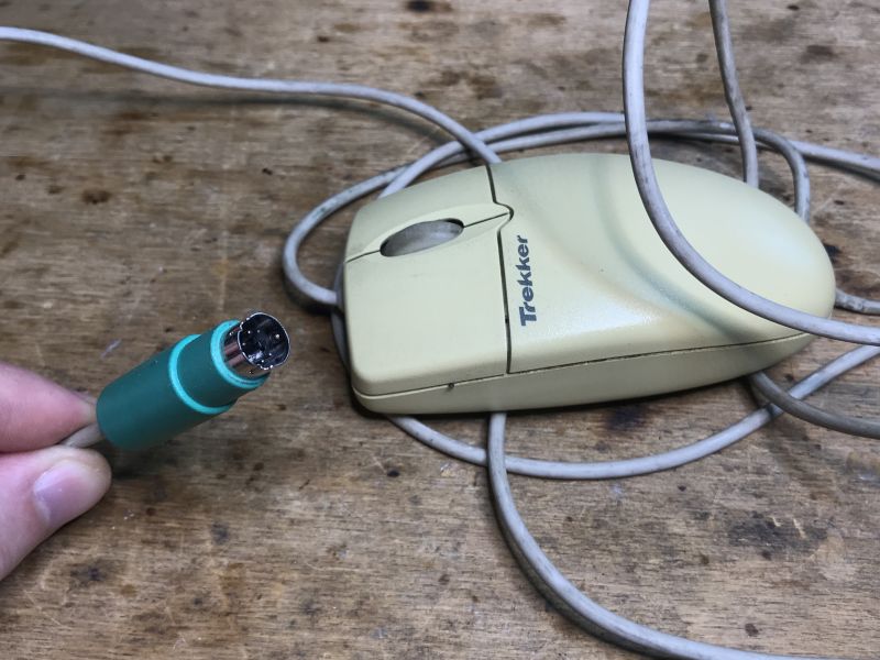
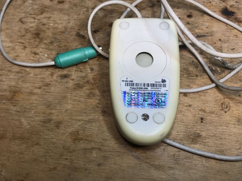
Third Trekker Third Trekker.
This time a mouse with a wheel but rated at 5V 15mA, could it be that they have optimised something?
 .
.
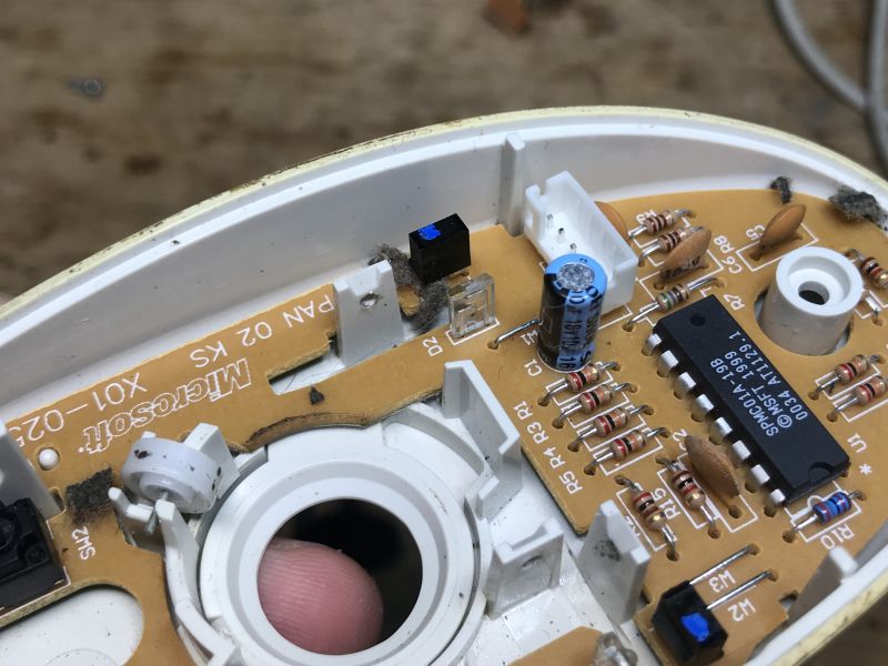
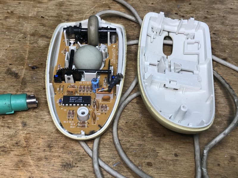
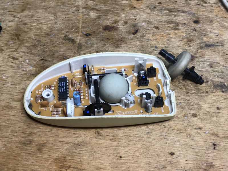
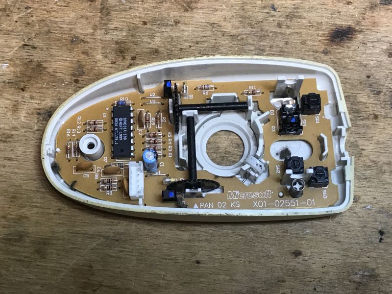
We take a look inside - the build is very similar to previous builds. This one is based on the SPMC01A-19B:
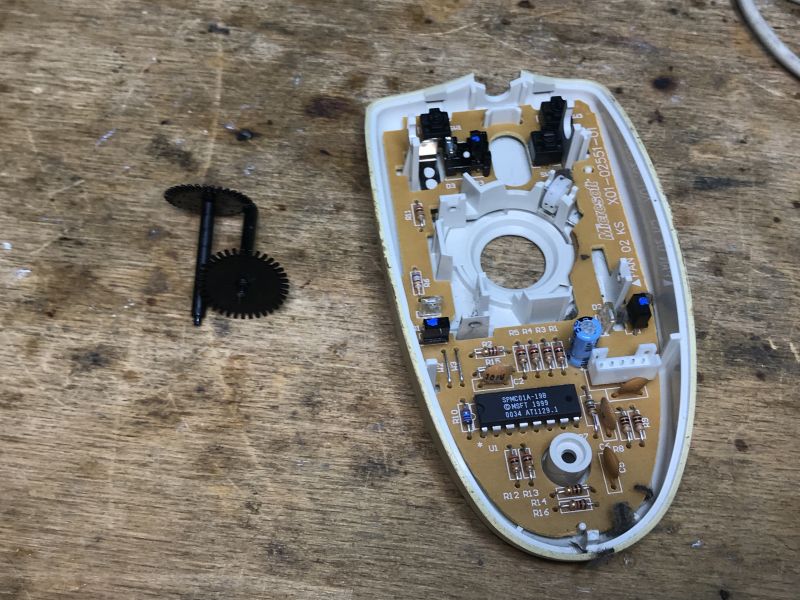
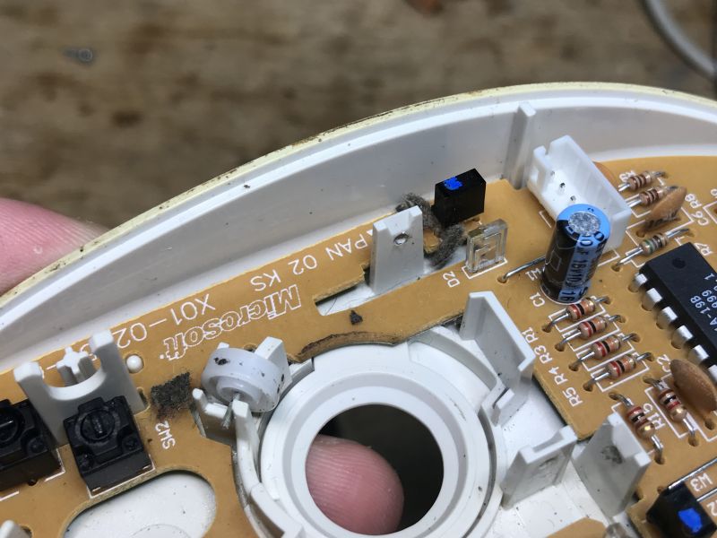 .
.
Removed:
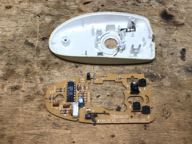
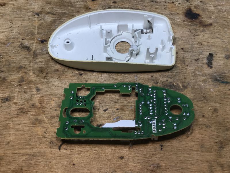 .
.
A4Tech OK-720 .
Time for a break from the Trekker. This time a mouse under the famous A4Tech logo:
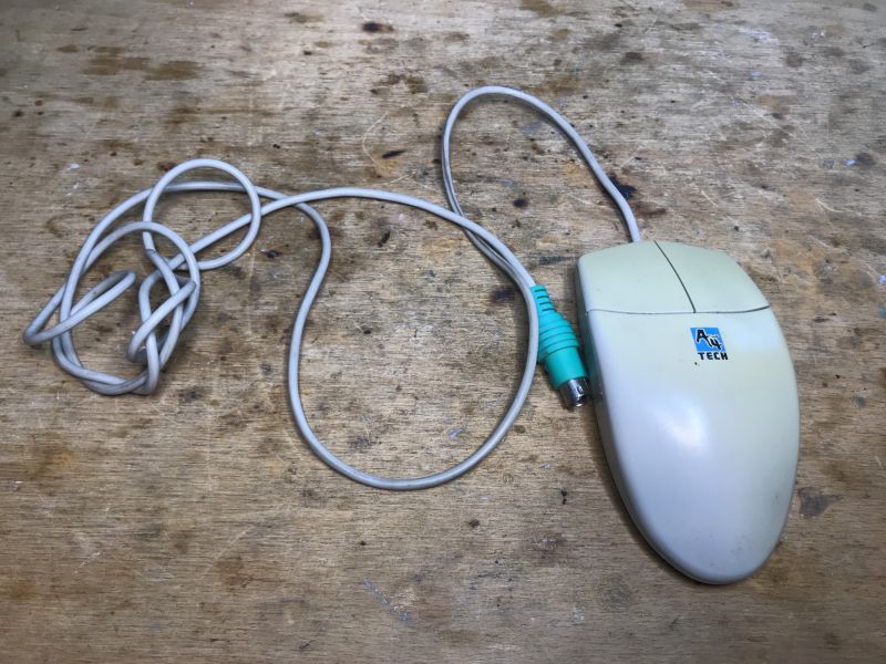 .
.
Fast Mouse
OK-720
12V.....10mA
12V? It's the PS/2 port that doesn't have 5V?
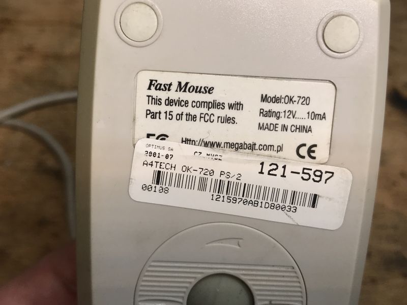
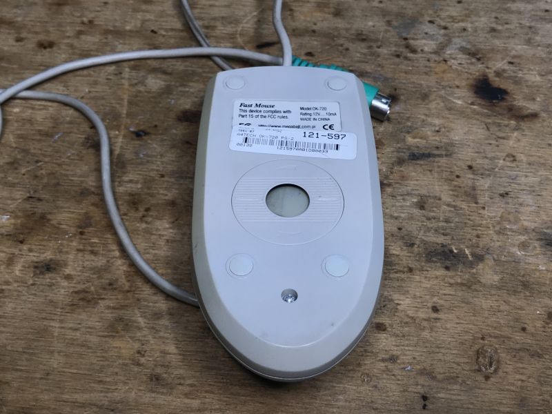 .
.
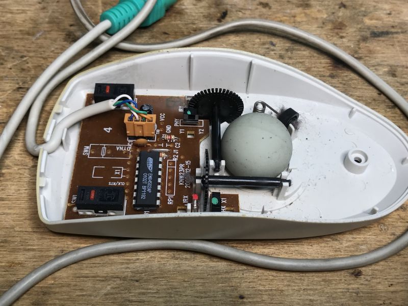
This mouse is two-button, but the board was also for the wheel version:
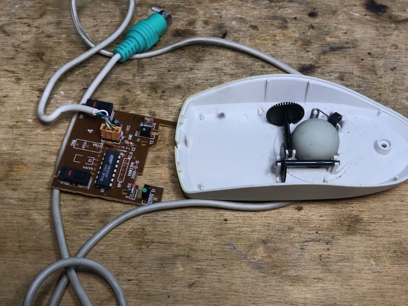 .
.
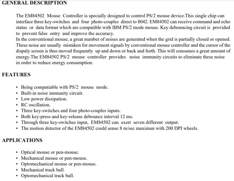
The date on the board is 2000-12-15, at this point it's about 24 years ago! The main controller is an EM84502AP.
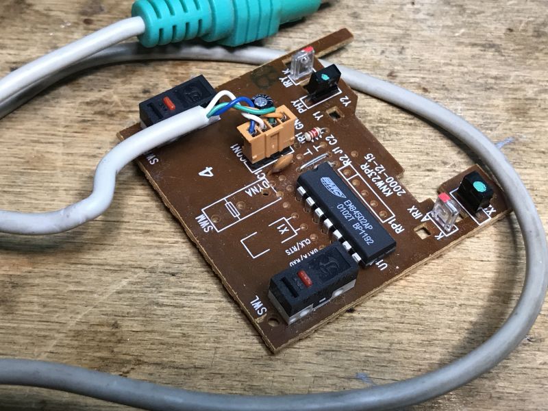 .
.
Switches:
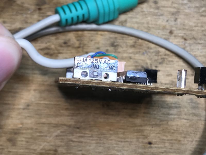 .
.
Simple, single-sided board:
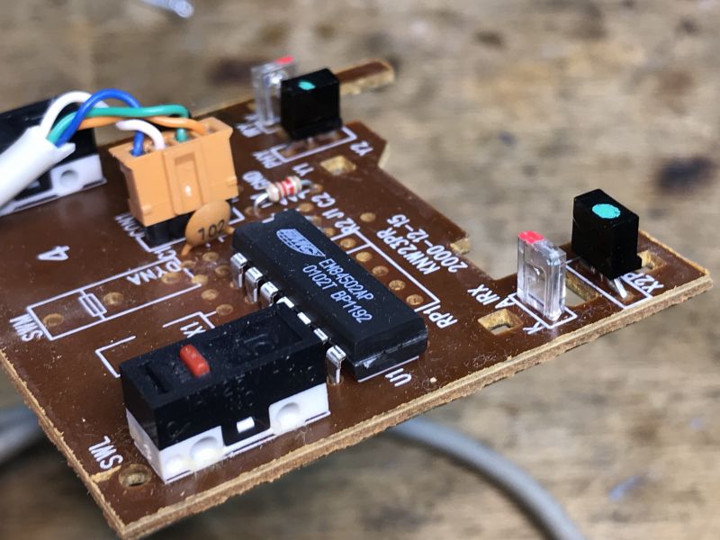
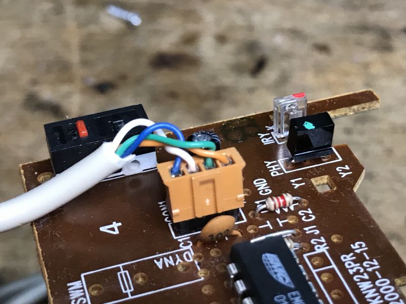
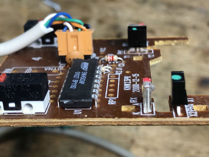
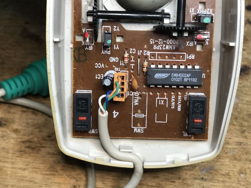
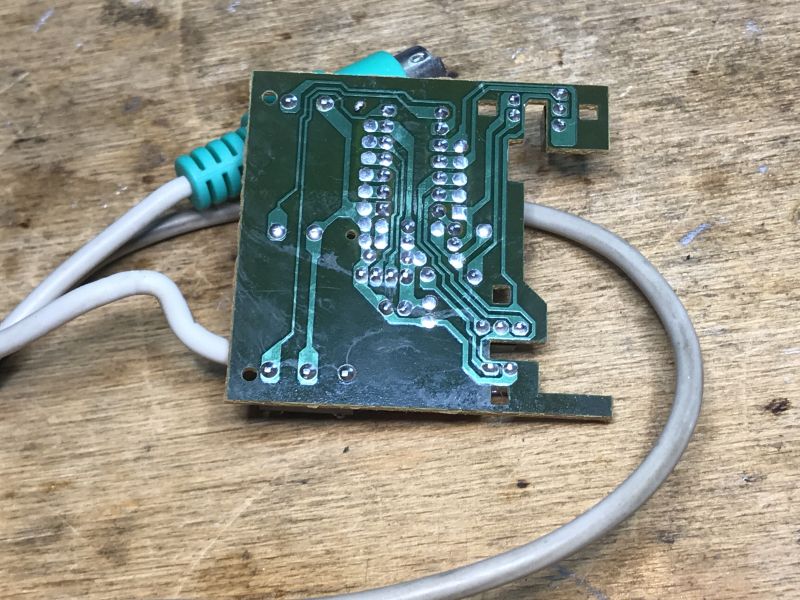 .
.
The EM84502AP, on the other hand, does not appear to be programmable:
 .
.
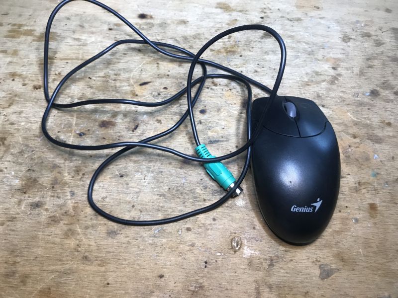
Slightly newer Genius .
Another mouse:
 .
.
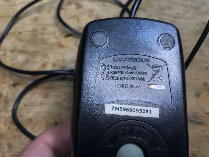
Model: NetScroll, a little less information.
 .
.
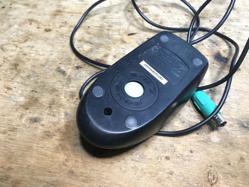
Looking in:
 .
.
As usual, the mouse qualifies for cleaning inside:
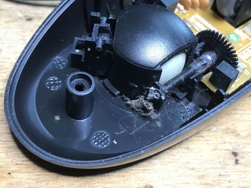 .
.
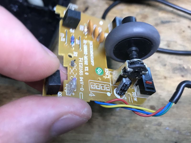
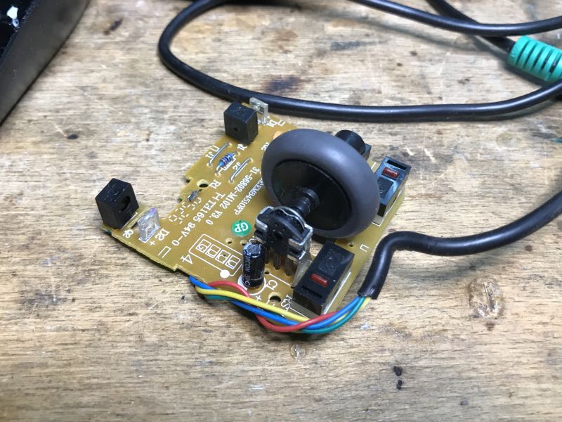
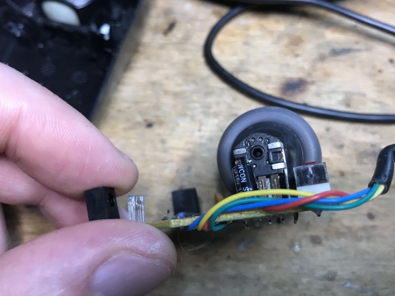
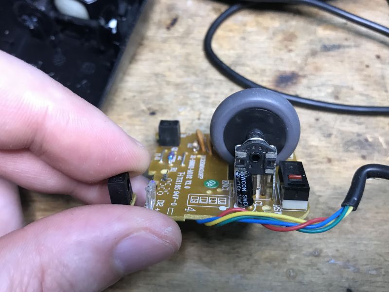
Oh, that's interesting, here the wheel is implemented differently - there is an encoder for the wheel.
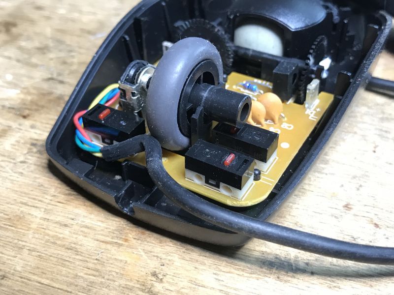
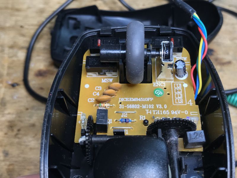
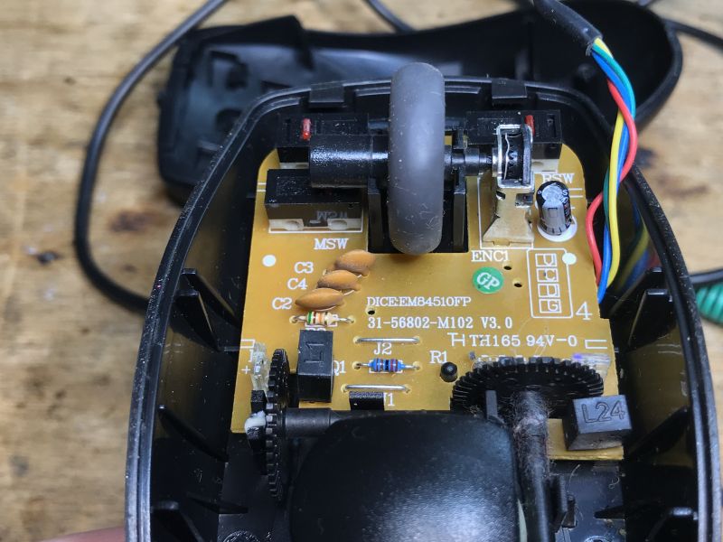 .
.
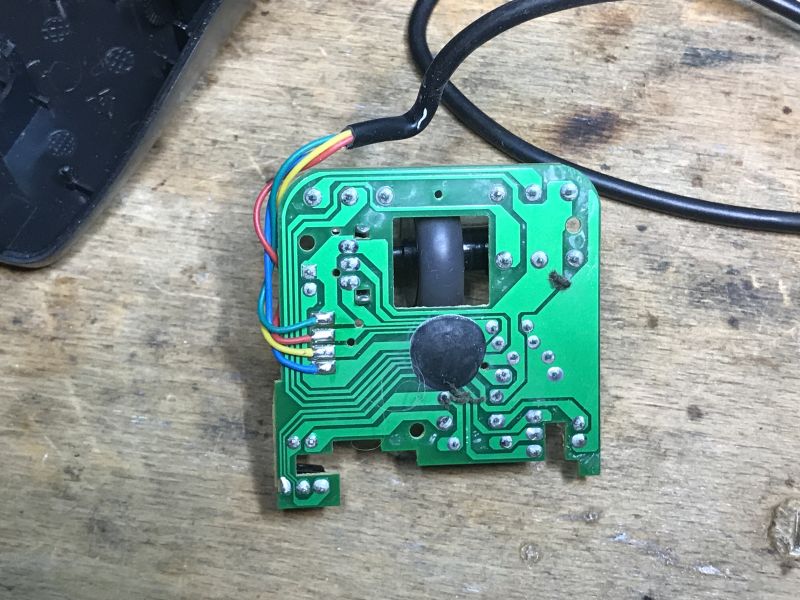
But where is the integrated circuit? Let's make the PCB free:
 .
.
Unfortunately.... and the wires are also soldered to the PCB, you can see that they have learned to save money over time. Why pay for a plug and connector?
Profiled mouse .
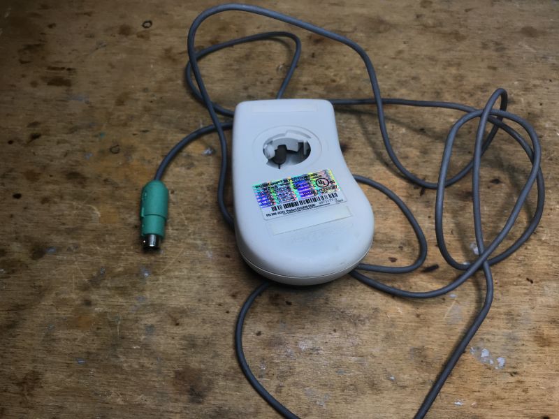
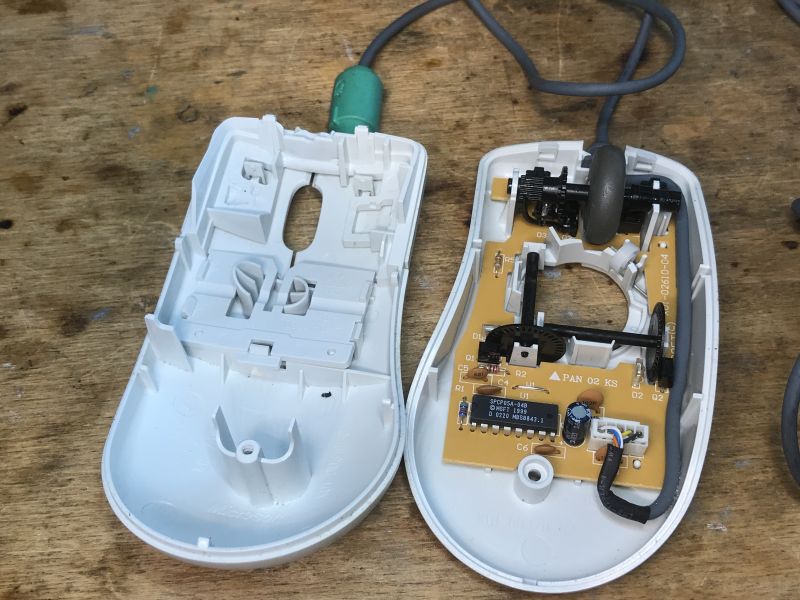
Now it is time for equipment that is not symmetrical:
 .
.
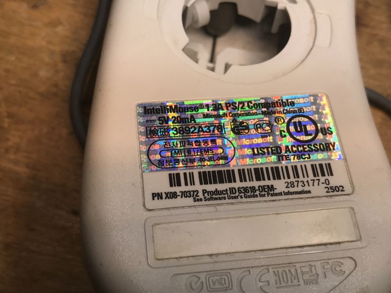
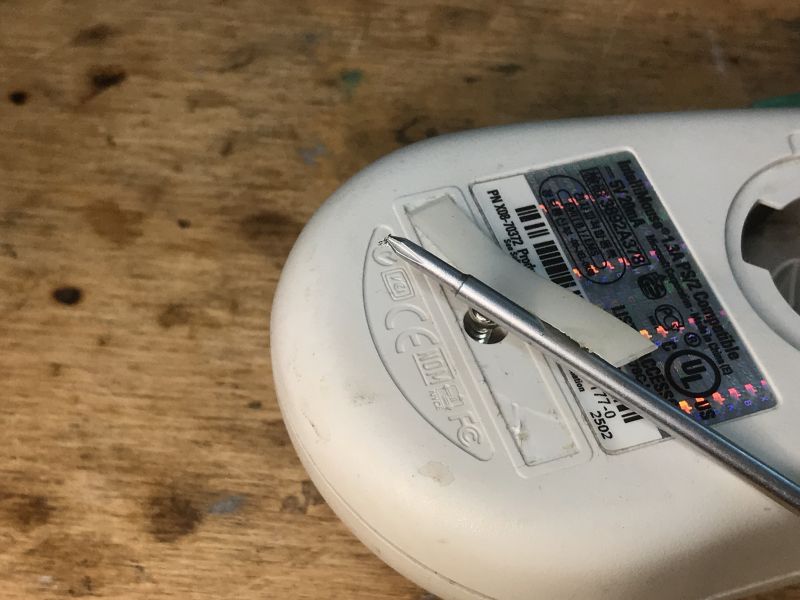
This time without the ball. We are looking for a screw:
 .
.
We take a look inside:
 .
.
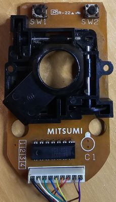
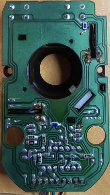
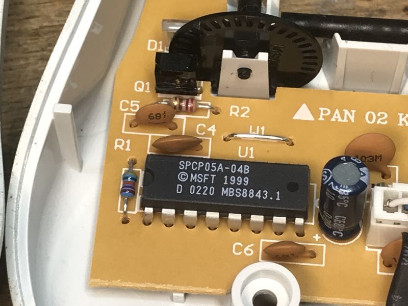
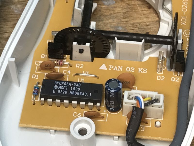
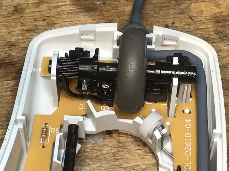
This mouse is based on the SPCP05A:
 .
.
I have already mentioned the SPCP05A a few mice above.
This is another one.... but without the ball .
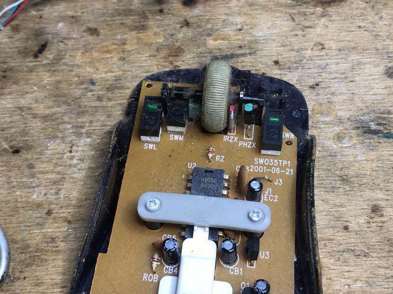
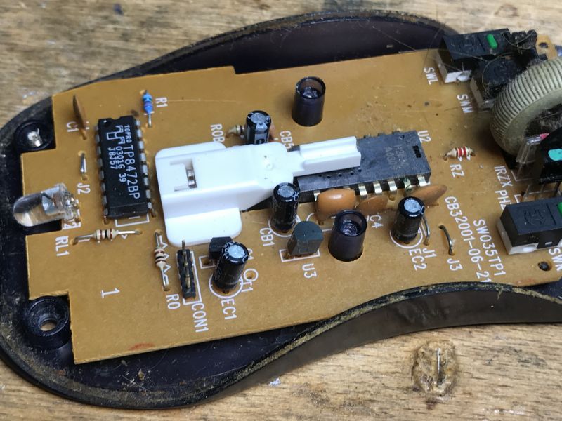
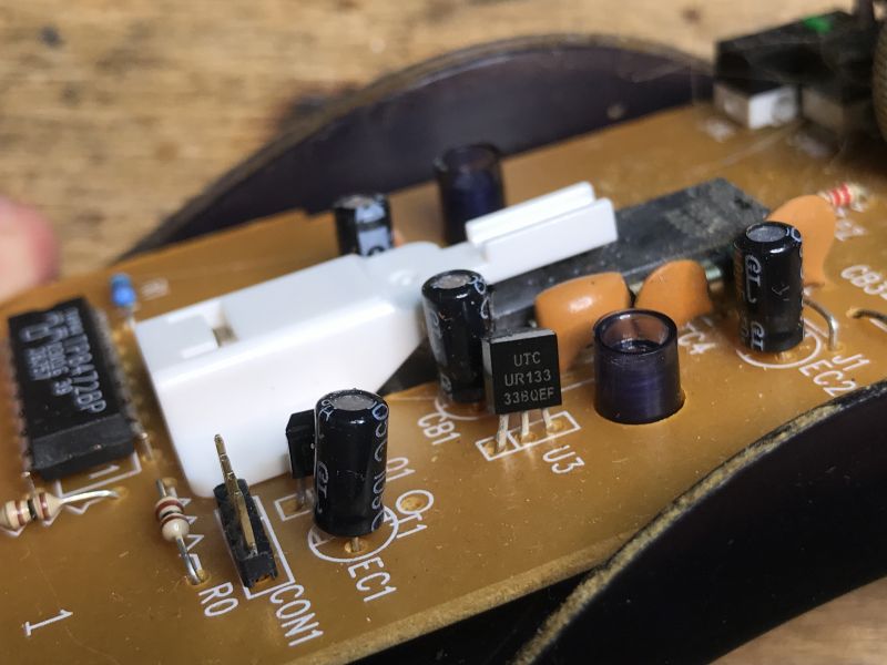
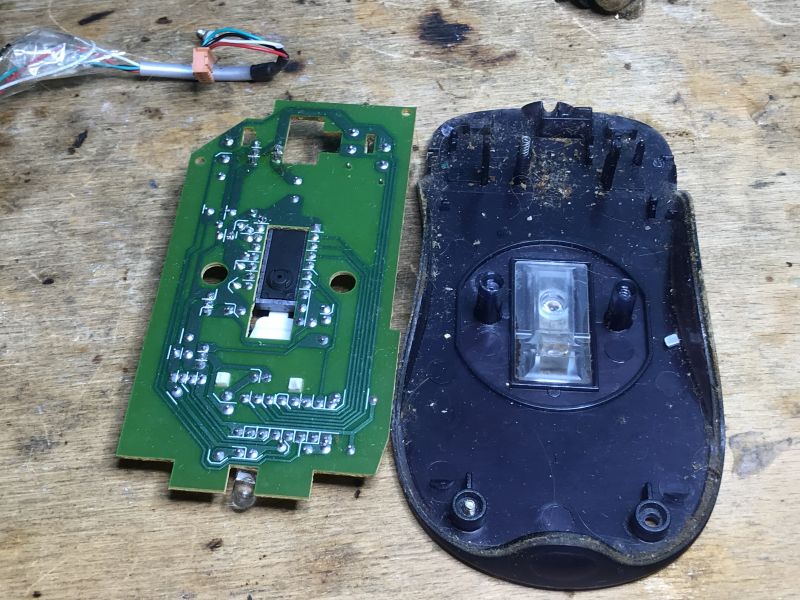
A slightly newer mouse this time - a laser mouse. Do you prefer this solution or the classic ball-and-socket?
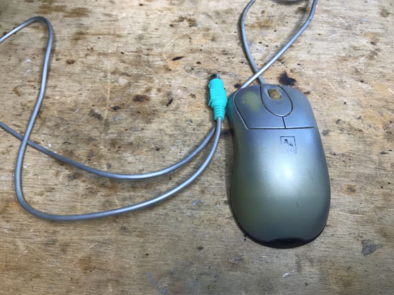
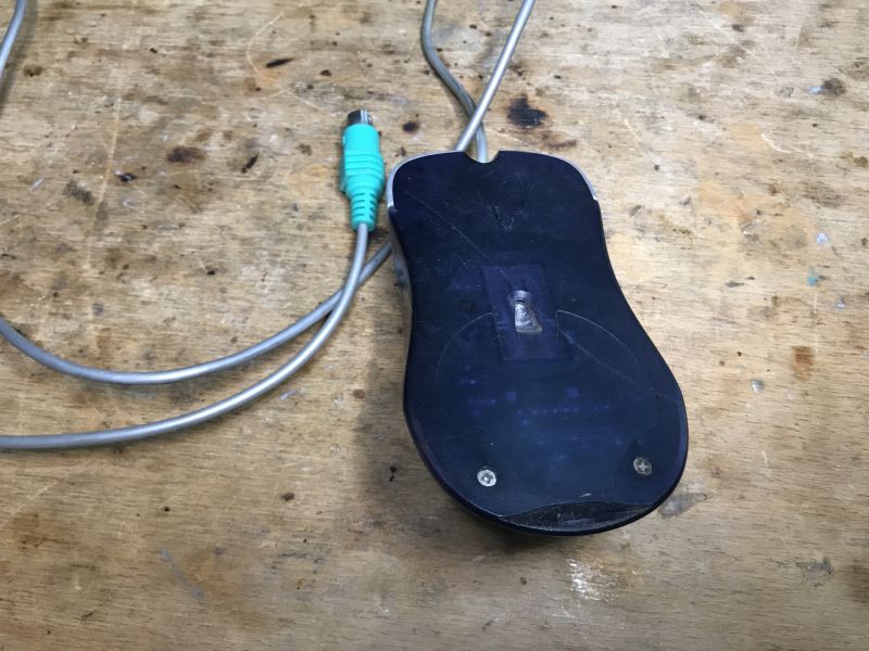 .
.
Let's take a look inside:
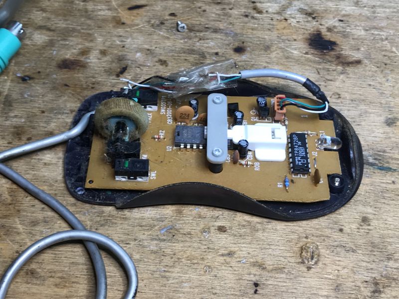 .
.
Someone here has replaced the wire and without soldering.
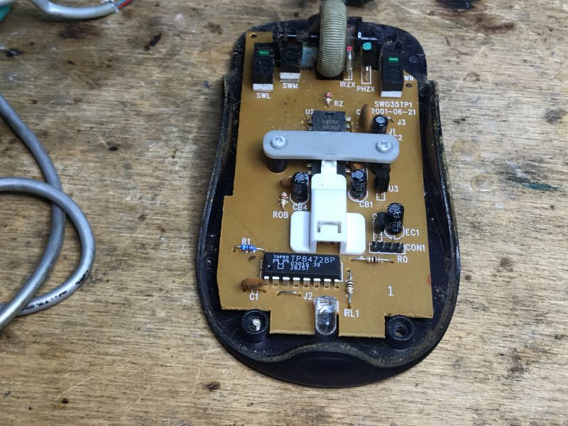 .
.
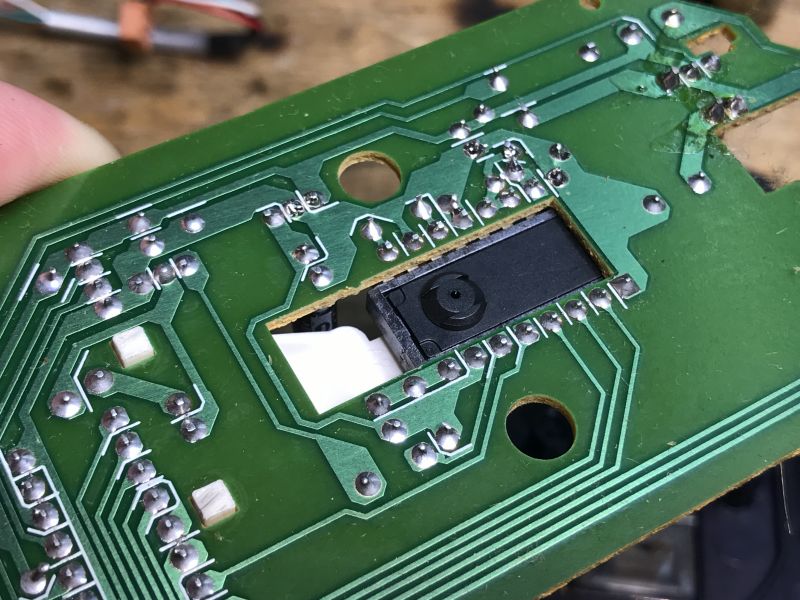
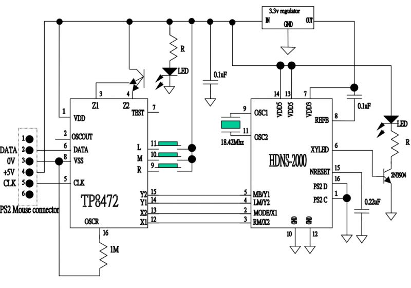
The mouse is based on the TP8472BP.
 .
.
The U2 is probably an optical sensor, so the layout probably looks more or less like this:
 .
.
The optical sensor receives the light from the LED reflected from the desk and converts it into movement along the X/Y axis.
Mouse communication protocol with PS/2 .
We will use the EM84502AP catalogue note here. But first we will start with the basics.
Here we have 4 signals:
- 5V
- ground
- clock (CLK)
- data (DATA)
Communication here is bidirectional. Normally it is the mouse that sends data to the computer.
The clock and data are pulled up to 5V through resistors.
The data sent to the PC is read during the falling edge of the clock.
One byte is sent between the start bit (0), the parity bit (1 if the number of ones is even), and the stop bit (1).
 .
.
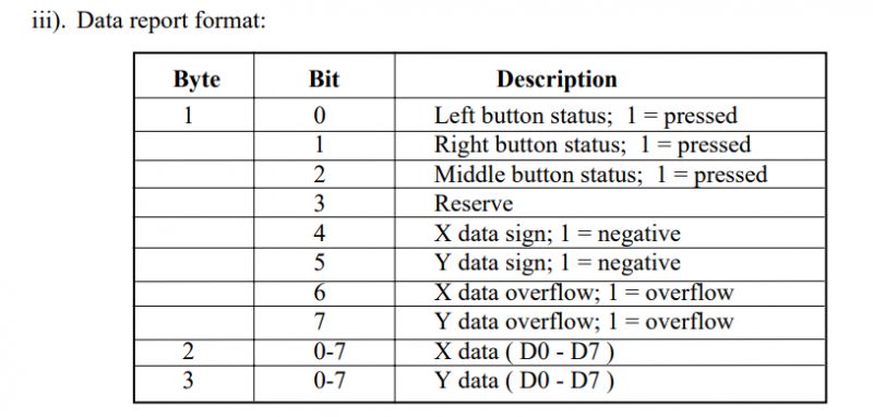
The format of the frame reported by such a mouse is really very simple. The individual bits correspond to the keys, we also have bits encoding the characters and the X and Y overflow, and separately we have the 8-bit values of these X and Y.
 .
.
Now just a question, how can we here still add sending data to the mouse from the computer? Or to the keyboard, e.g. sending Caps Lock?
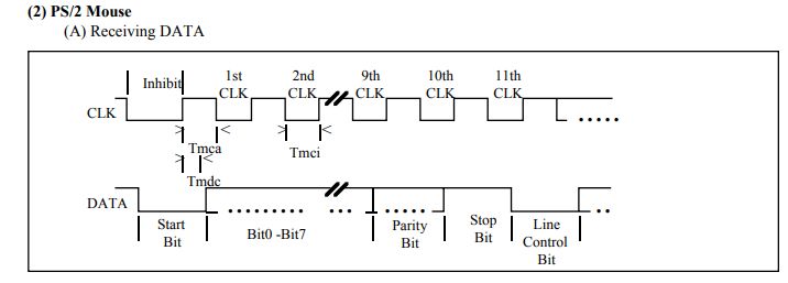
If the host wants to send data, it just has to signal it - set a low state on the clock line for at least 100 microseconds, then the data line too. Then the clock is released and the mouse controls it again, then the data transfer takes place. The data sent by the PC to the mouse is read on the rising edge of the clock:
 .
.
The catalogue note also describes the commands that this chip receives:
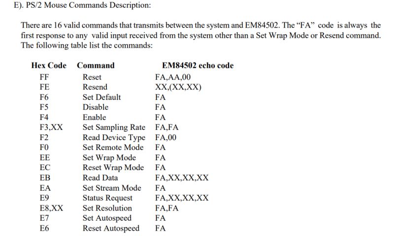 .
.
Of course, these are not commands just for this chip, they are basically standard, you can read more here: https://wiki.osdev.org/PS/2_Mouse
Perhaps for a more detailed presentation of the protocol I will try to implement it e.g. on an AVR, but there are also ready-made libraries for Arduino under keyboard and mouse on the internet, e.g:
https://github.com/PaulStoffregen/PS2Keyboard
https://github.com/jazzycamel/PS2Mouse
You can take a look at their code to see how the implementation of the communication protocol looks like in practice.
Summary .
I myself already started with a USB mouse so the topic of older versions of "rodents" interested me enough to make the gallery shown here. Probably the biggest curiosity I got from this topic is that older ball mice work on the same principle as encoders from printers, which I discussed in a separate topic:
Teardown of an HP Deskjet D1360 printer and an example of using its parts with an Arduino .
By the way, I already showed a mouse on the forum, but one still on RS232:
Interior of an old RS232 ball mouse and its communication protocol .
Aside from that, I'd like to add that I'm nostalgic for this type of mouse - these were in my primary school computer lab. What kind of mice have you used? Do you have any interesting exhibits?
Cool? Ranking DIY Helpful post? Buy me a coffee.


