FAQ
TL;DR: Use 3.3 V UART; “toggle the 3v3 power off/on until Easy Flasher catches it” to enter download mode. This FAQ helps Glow Ray 4in owners reflash firmware 1.5.21 via serial when CEN isn’t obvious. [Elektroda, divadiow, post #21328729]
Why it matters: It shows how to wire, power, and time UART mode safely when CloudCutter won’t work.
Quick Facts
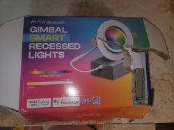
- Confirmed model: LED-4g-SMD-10w-SWF-RD-WF (Approx. 10 W). [Elektroda, yonubear, post #21328683]
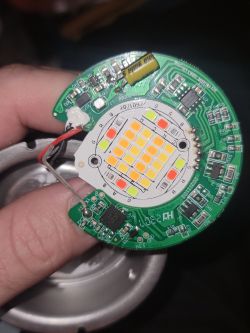
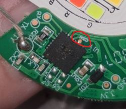
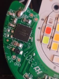
- Controller marking seen as “T34”; a CEN pad was identified on the LED disk photo. [Elektroda, divadiow, post #21328729]
- Power from an external 3.3 V source only; do not have mains connected during serial work. [Elektroda, divadiow, post #21330993]
- Wiring: share GND, cross TX↔RX, keep leads short, verify pogo continuity; solder short leads if possible. [Elektroda, divadiow, post #21331101]
- Easy Flasher can catch UART download by timing quick 3.3 V power toggles. [Elektroda, divadiow, post #21328729]
How do I identify the SoC and the CEN/EN pad on this Glow Ray 4in board?
Look for a "T34" marking on the controller area of the LED disk. In shared photos, a CEN pad was circled for entry control. If CEN isn’t obvious, you can still try the power‑toggle UART method described below. [Elektroda, divadiow, post #21328729]
Can I enter UART download mode without locating CEN?
Yes. Time the bootloader by cycling power: “toggle the 3v3 power off/on until Easy Flasher catches it in uart download mode.” This lets the tool grab the boot window without pulling CEN. Use a 3.3 V USB‑TTL setup. [Elektroda, divadiow, post #21328729]
What’s the correct UART wiring (TX/RX, VCC, GND) for these lights?
Power the board from an external 3.3 V PSU only. Share ground between the PSU and your USB‑TTL adapter. Cross data lines: bulb TX → adapter RX, bulb RX → adapter TX. Keep leads short and verify continuity to the contact tips. Prefer soldered short leads. [Elektroda, divadiow, post #21331101]
Is it safe to leave mains connected while using the serial adapter?
No. As one expert put it, “eek! don’t do that!” Use only an external 3.3 V source while you work. Mains during UART can damage hardware and risk shock. Disconnect mains before attaching your serial rig. [Elektroda, divadiow, post #21330993]
I’m using pogo pins and can’t connect—what should I change?
Shorten all wires and check continuity at the very end of each pogo tip. Cross TX/RX correctly and share ground across PSU and adapter. If it stays flaky, solder short wires to 3.3 V, GND, RX, and TX for a solid link. [Elektroda, divadiow, post #21331101]
What tool should I use to catch the bootloader?
Use Easy Flasher in UART mode and time a quick 3.3 V power cycle so it “catches” the boot window. This avoids needing a direct CEN pull. Keep your serial connections stable while toggling power. [Elektroda, divadiow, post #21328729]
Will the light still work after failed serial attempts?
Yes, the OP reported the lamp reconnects to Wi‑Fi and Tuya when powered normally. That indicates the device isn’t bricked by the attempts. Resume flashing only after confirming wiring and power safety. [Elektroda, yonubear, post #21331936]
What exact model and power rating does this thread cover?
It covers Glow Ray model LED-4g-SMD-10w-SWF-RD-WF, which is approximately a 10 W recessed gimbal assembly. Use this identification when searching pinouts or firmware notes. [Elektroda, yonubear, post #21328683]
How should I share the factory firmware backup for analysis?
After you capture the stock firmware with your flashing tool, post the backup file in the thread. A contributor requested it for analysis to help others. Include wiring notes and versions. [Elektroda, divadiow, post #21328740]
Do RX and TX need to be crossed when wiring the USB‑TTL?
Yes. Connect the bulb’s TX to the adapter’s RX, and the bulb’s RX to the adapter’s TX. Share ground between the PSU, bulb, and adapter to complete the link. [Elektroda, divadiow, post #21331101]
3-step: How do I attempt a UART flash via power‑toggle?
- Hook up a 3.3 V UART interface to the board and your PC.
- Open Easy Flasher in UART download mode.
- Toggle 3.3 V off/on repeatedly until the tool detects the bootloader and connects.
[Elektroda, divadiow, post #21328729]
What quick bench test shows the SoC is alive on 3.3 V power?
With only 3.3 V and GND connected, check if it appears for pairing or broadcasts an access point. That suggests the SoC boots and responds. If not, recheck wiring and power stability. [Elektroda, divadiow, post #21331184]
If timing the power‑toggle never works, what’s the next step?
Ditch pogo pins and solder short, solid leads to 3.3 V, GND, RX, and TX. Mechanical instability often blocks detection. Retest with the same timing approach after improving connection quality. [Elektroda, divadiow, post #21331973]
