logo elektroda
logo elektroda
X
logo elektroda

Ledvance Sun@Home Planon Plus + Ledvance Remote Control

philippeaellig 1857 27
ADVERTISEMENT
  • #1 20837652
    philippeaellig
    Level 3  
    Hi there, I would like to free my Ledvance lamps from the cloud. That should work.
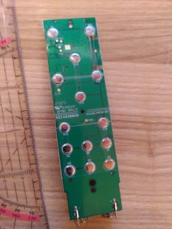
    But I still have a question. I would also like to continue using the Ledvance Remote Control. They have a BK7231N chip in them. You don't pair the remote with the app, but connect it directly to the lamp. That's why I can't flash it with tuya-cloudcutter, as I probably can with the lamp. Is it possible to flash the remote with the OpenBeken firmware without soldering? The SMD BK7231N chip is very tiny. You can't solder it. There is a small QR code on the board, but it only contains a number, not a URL. There are six points on the back of the board where you could solder something: 3.3V, GND, RX, TX, CEN and CSN.
    Produkt Link
    Tuya Cloudcutter]
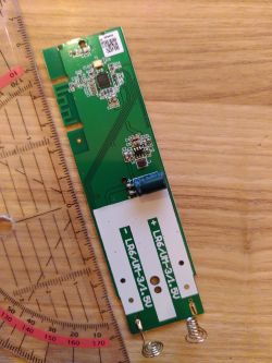
    Ledvance remote control circuit board with BK7231N chip. A circuit board with trace markings and solder points.
  • ADVERTISEMENT
  • #2 20837861
    p.kaczmarek2
    Moderator Smart Home
    There are required pads available, can you solder to them? Just make sure to make 2MB flash backup first.

    Are you sure that this remote works in WiFi mode and not as Bluetooth/?
    Helpful post? Buy me a coffee.
  • #3 20838246
    philippeaellig
    Level 3  

    Thanks for your answer.
    Yes, I can solder to them.
    Good question, I guess it works with Bluetooth because I can't see the remote in my network.
  • #4 20838325
    p.kaczmarek2
    Moderator Smart Home
    Well, for a start, you can just do 2MB flash read and it will tell us more about this device. Do not flash OBK yet.
    https://github.com/openshwprojects/BK7231GUIFlashTool
    Helpful post? Buy me a coffee.
  • ADVERTISEMENT
  • #5 20839131
    philippeaellig
    Level 3  

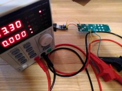
    I tried it. But I was unsuccessful. I have an USB UART CH340G Adapter. I have connected TX to RX and RX to TX. At first I also connected VCC and GND to the BK7231N. Unfortunately it did not work. That's why I tried it with an external power supply.

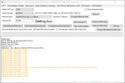
    I selected the UART port and then clicked on "Read only OBK config". Then I switched on the power supply so that the device starts. That did not work. I also tried to connect 0.25 seconds CEN to GND. But that didn't work either. I tried many times with a metronome.

    Workbench with a power supply and electronic board connected to a USB UART CH340G adapter. Screenshot of BK7231 Easy UART Flasher program with connection errors.
  • #6 20839145
    p.kaczmarek2
    Moderator Smart Home
    It is always necessary to connect common ground as well. USB to UART convert ground must be connected to PCB, because RX/TX signals are in reference to ground. It will not work if you don't connect a common ground.
    Helpful post? Buy me a coffee.
  • #7 20839217
    philippeaellig
    Level 3  

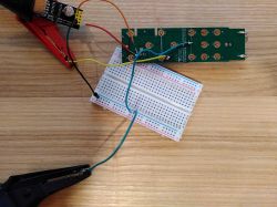
    I tried this too, but the result is the same.

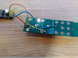
    Setup of an electronic circuit on a breadboard with connected wires.
    Circuit board with soldered wires placed on a wooden surface.

    edit:
    i checked the Bk7231N and found a problem: TX is labeled as RX and RX is labeled as TX. So, i have to connect TX to TX and RX to RX.

    {
    	"Jsonver":"1.0.0",
    	"blindt":"8",
    	"module":"CBU",
    	"nightbrig":"5",
    	"bristep":"20",
    	"hsvstep":"20",
    	"keylt":"3",
    	"keyglobefunc":"[[9",
    	"step_rate":"20",
    	"category":"0505",
    	"keyccfg2":"10",
    	"tempstep":"20",
    	"nightcct":"0",
    	"keyccfg1":"9",
    	"crc":"30",
    	"prod_test":"false",
    	"fac_pin":"db3angmsimkndxht "
    }

  • #8 20842154
    philippeaellig
    Level 3  

    @p.kaczmarek2 What do I have to do now with the 2MB flash read?
  • #9 20842523
    p.kaczmarek2
    Moderator Smart Home
    The 2MB flash read is required to get Tuya JSON config. In most of the devices it will contain your GPIO data, but in the case of your device, I can't see any GPIO information there. It seems that you need to find our GPIO roles manually, maybe with GPIO Doctor from our Web App.
    Helpful post? Buy me a coffee.
  • #10 20848215
    philippeaellig
    Level 3  

    I have to give up. The TX and RX pads on the remote control have fallen off. I'm not a good solderer.


    What I have figured out:

    Ledvance Sun@Home Planon Plus + Ledvance Remote Control

    P7 (PWM 1)S2 (Book)P15
    P6 (PWM 0)S3 (B)P15
    P26 (PWM 5)S4 (Palm tree)P15
    P7S6 (Screen)P17
    P6S7 (A)P17
    P26S8 (Moon)P17
    P8S9 (ON)P9
    P7S10 (OFF)P9
    P6S11 (warmer)P9
    P26S12 (darker)P9
    P8 (PWM 2)S13 (less saturation)P28
    P7S14 (brighter)P28
    P6S15 (more saturation)P28
    P26S16 (colder)P28


    I guess that the PIN P15, P17, P9 and P28 are listening to the PWM Signals from O8, P26, P7 and P6. And when a button is clicked and the PWM signal arrives, you then know which button is clicked. Unfortunately, I do not yet understand how to input this into OpenBK.
  • #11 20848530
    p.kaczmarek2
    Moderator Smart Home
    So it's a classic matrix keyboard. Should be easy to support, but would require some programming knowledge.
    Helpful post? Buy me a coffee.
  • #12 20848747
    philippeaellig
    Level 3  

    Developing is not the problem, I am a developer. But I don't know how to implement this with ODK.
  • #13 20848775
    p.kaczmarek2
    Moderator Smart Home
    Have you ever implemented a matrix keyboard scan on any platform?

    In OBK, you can either utilize a RTOS timer or use our quicktick timer, which fires every 25ms. And then, repeatedly, set one of the matrix columns to high state, and then sample the rows. Then again, set another column to high state, and sample rows again. Etc, etc. You may need to take in the account the propagation time, but it can be done easily.

    I can write a driver stub for you in C, and then we can finish that one together.

    Is the device flashed with OBK already? If so, then you don't need RX/TX, you can update via WiFi.

    Alternatively, you could send me the board with the broken pads and I think I may be able to restore them and use it for development.
    Helpful post? Buy me a coffee.
  • ADVERTISEMENT
  • #14 20848778
    philippeaellig
    Level 3  
    Yes, it's already flashed with OBK.
  • #15 20848811
    p.kaczmarek2
    Moderator Smart Home
    Okay, so, do you know C? Would you like to help with the code, or maybe, I can just try to make the driver draft myself and just let you test?

    I could prepare a first version today, but it may require several testing attempts and fixes.

    Pseudocode would be:
    
    set P9 to high, others low
    sample P8
    sample P7
    sample P6
    sample P26
    set P28 to high, others low
    sample P8
    sample P7
    sample P6
    sample P26
    // etc, etc, etc
    
    Helpful post? Buy me a coffee.
  • ADVERTISEMENT
  • #16 21510794
    gelbetomate
    Level 3  
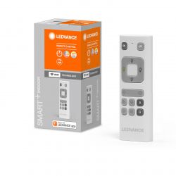
    Hi, I recently had the chance to buy 2 of these Ledvance Planon Plus lamps including this remote control.

    The first remote I flashed with OBK. I tried it several times to back up with a lot of tricks and tweaks I read in this forum, but didn't succeed. It always stopped and had a time out after a while. So I took one statement I found "not possible with N" and just started to write OBK and this succeeded the first time without any trouble.

    But now I have a blank OBK and wanted to apply a as supported listed Template for this remote, but the Template seems to be empty and is referencing to this thread for more information.

    Until now I did not find further information and I'm wondering if one went on with his analyses and can share it?

    btw I'm willing to do some tests and I still have this device with the original firmware.
  • #17 21510844
    p.kaczmarek2
    Moderator Smart Home
    Can you show some detailed photos of your device?

    I'm not yet even sure how this remote can work, is it using BT or some kind of WiFi like ESPnow? @insmod ,any ideas?
    Helpful post? Buy me a coffee.
  • #18 21510877
    gelbetomate
    Level 3  
    It's exactly the same one analyzed by @philippeaellig

    It's using wifi.

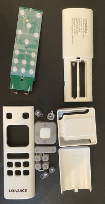
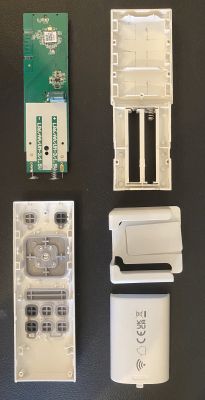
    Circuit board with components and attached wires.
    Disassembled LEDVANCE remote control showing internal components and individual parts.
    Disassembled remote control with visible internal components and casing on a black background.
  • #19 21510881
    p.kaczmarek2
    Moderator Smart Home
    So this remote has a pairing process where you enter your SSID and pass? And it connects to your router?
    Helpful post? Buy me a coffee.
  • #20 21510893
    gelbetomate
    Level 3  
    well, I did not use the ledvance app for now, but it looks like you first pair your lamp with the mobile app and then you bring your lamp into pairing mode and connect the remote to it. I do not know if this is using WIFI or BT.

    https://www.ledvance.com/00_Free_To_Use/asset...1_smart-_wifi_installation_remote_control.pdf

    adding this video, as you can see the process and the app
    (51) So einfach koppelst du die LEDVANCE SMART+ WiFi Fernbedienung mit einer LEDVANCE SMART+ WiFi Lampe! - YouTube

    https://www.youtube.com/watch?v=7Y7D66_HfMw

    it is saying wifi remote.
  • #21 21519297
    gelbetomate
    Level 3  
    I would be simply happy if I can use the remote buttons in my wifi network to trigger an event in HA or MQTT or both. No need to implement any pairing mode or other features provided by a direct connection between remote and lamp which might be using BT.

    So, now trying to understand if the matrix keyboard mentioned above has been implemented and how to use it?

    Simple Scenario One: trying to use button S2 on the remote using what I understand from the table listed above:

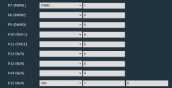
    Pin configuration with their modes and values.

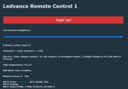
    this is simply triggering the "Toggle Light". Slow but proven now, it's leveraging wifi yeah, but it's not only working for S2 also other buttons are triggering the toggle... hmmm

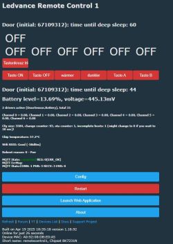
    Ledvance Remote Control 1 interface showing status information and a toggle light function.

    I don't want the "LED Dimmer/Brightness" slider, but this comes from PWM, I guess.

    I'm still new to OBK and this type of configuration. Every hint can help ;-)
  • #22 21525322
    pirkelt
    Level 3  
    Hello all,

    formerly i experimented with this remote control, too. It´s important to know the unit includes a (very low) power stepup converter to boost the battery voltage to 3.3V. The converter is always on. So i use this unit with rechargeable batteries. The ADC Port is free, but they designed solderpads on PCB for 0402 Resistors. One to ground (i use 2,2 Megohm Resistor) and the second to VCC from regulator (why ?). I soldered the second Resistor (2,7 Megohm) directly to batteryport to monitor the Batterysupply. In sleep the Unit draws only 30-40 microamps with regulator.
    Wakeup is a simple push on a button in the "Keycross" area. The Remote starts, within 6 seconds is the unit ready connected.  
    The blue WiFI LED is switched on during operation for 90 seconds, goes off for two seconds to warn me for disconnection/sleep down in 10 seconds.

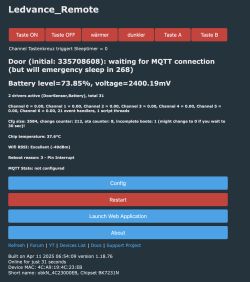
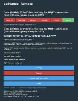
    Ledvance_Remote control panel with buttons, device, battery, WiFi data, and configuration options.

    In my configuration i can use 6 buttons (devices). In my application some buttons supports multiclick (like the old WiFi Shelly Button 1).


    Here is my autoexec.bat with comments

    // PowerSave 2
    alias mode_wifi setPinRole 14 WifiLED
    alias mode_relay setPinRole 14 AlwaysHigh

    // at reboot, set WiFiLEd
    mode_wifi
    // then, setup handlers
    addChangeHandler WiFiState == 4 mode_relay
    addChangeHandler WiFiState != 4 mode_wifi

    SetChannelLabel 1 "Taste ON"
    SetChannelLabel 2 "Taste OFF"
    SetChannelLabel 3 "wärmer"
    SetChannelLabel 4 "dunkler"
    SetChannelLabel 5 "Taste A"
    SetChannelLabel 6 "Taste B"
    SetChannelLabel 0 "Tastenkreuz triggert Sleeptimer"

    Battery_Setup 0000 3250 1.00 3250 2570 // Spannungsteiler 2M4+2M7 @3V
    Battery_cycle 29 // Aktualisierung in sek.

    addEventHandler OnClick 7 backlog SendGet http://192.168.0.78/white/0?turn=toggle&brightness=50 // P7 Aufruf GU10 TV
    addEventHandler OnDblClick 7 backlog SendGet http://192.168.0.78/settings?mode=white
    addEventHandler On3Click 7 backlog SendGet http://192.168.0.78/settings?mode=color // P7 Aufruf GU10 TV grün
    addEventHandler On4Click 7 backlog SendGet http://192.168.0.78/white/0?turn=on&brightness=100
    addEventHandler OnHold 7 backlog SendGet http://192.168.0.78/color/0?effect=1 // P7 Aufruf GU10 TV Animation

    addEventHandler OnClick 8 backlog SendGet http://192.168.0.79/white/0?turn=toggle&brightness=50 // P8 Aufruf GU10 Sofa
    addEventHandler OnDblClick 8 backlog SendGet http://192.168.0.79/settings?mode=white
    addEventHandler On3Click 8 backlog SendGet http://192.168.0.79/settings?mode=color // P8 Aufruf GU10 Sofa grün
    addEventHandler On4Click 8 backlog SendGet http://192.168.0.79/white/0?turn=on&brightness=100
    addEventHandler OnHold 8 backlog SendGet http://192.168.0.79/color/0?effect=1 // P8 Aufruf GU10 Sofa Animation

    addEventHandler OnClick 6 backlog SendGet http://192.168.0.88/cm?cmnd=Power%20Toggle // P6 Aufruf Pixel LED
    addEventHandler OnDblClick 6 backlog SendGet http://192.168.0.88/cm?cmnd=Color%207c2a00 // P6 Aufruf Pixel LED warm
    addEventHandler On3Click 6 backlog SendGet http://192.168.0.88/cm?cmnd=Color%2000FF00 // P6 Aufruf Pixel LED grün
    addEventHandler On4Click 6 backlog SendGet http://192.168.0.88/cm?cmnd=Color%2050c950 // P6 Aufruf Pixel LED kalt
    addEventHandler OnHold 6 backlog SendGet http://192.168.0.88/cm?cmnd=Anim%200 // P6 Aufruf Pixel LED Animation

    addEventHandler OnClick 26 backlog SendGet http://192.168.0.49/rpc/Switch.Toggle?id=0 // P26 Philips Scene LED

    addEventHandler OnClick 17 backlog SendGet http://192.168.0.47/rpc/Switch.Toggle?id=0 // P17 Funktisch schalten
    addEventHandler OnClick 15 backlog SendGet http://192.168.0.47/rpc/Switch.Toggle?id=1 // P15 LED (A2) schalten
    addEventHandler OnHold 15 backlog SendGet http://192.168.0.98/cm?cmnd=Power%20Toggle // P15 Aufruf Couch E27

    // give user time to play
    delay_s 90
    setPinRole 14 AlwaysLow
    delay_s 2
    mode_relay
    delay_s 10
    // sleep either until pin wakeup
    PinDeepSleep


    and my pin configuration:

    "pins":
    "6": "Btn;3",
    "7": "Btn;2",
    "8": "Btn;1",
    "9": "AlwaysLow;0",
    "14": "WifiLED;0",
    "15": "dInput_n;0",
    "16": "dInput_n;0",
    "17": "dInput_n;0",
    "23": "BAT_ADC;0",
    "26": "Btn;4",
    "28": "DoorSnsrWSleep_nPup;0"


    Thank you very much for this great Project!

    Thomas
  • #23 21525325
    p.kaczmarek2
    Moderator Smart Home
    Good job, make sure to include the new "Quick connect to WiFi" flag/mechanism by @insmod

    Well, isn't ADC port used (or supposed to be used) for battery voltage check? I've read reports that having too low voltage corrupts BK7231 flash and then you have to flash whole 2MB image again to recover it.
    Helpful post? Buy me a coffee.
  • #24 21525678
    pirkelt
    Level 3  
    -> Good job, make sure to include the new "Quick connect to WiFi" flag/mechanism by @insmod

    Thanks!
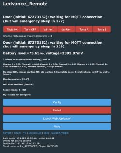
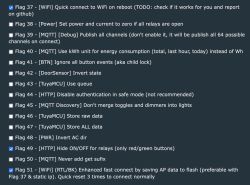
    I tried this new "Quick reconnect feature", but the unit starts two times and the reconnecting is much slower. It needs sometimes up to 30 seconds!

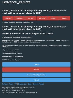
    Ledvance_Remote control panel with control buttons and device status information displayed.

    Web interface of a Ledvance Remote device showing connection status, battery level, and control buttons.

    A list of advanced device settings, mainly related to WiFi, MQTT, HTTP, and power settings, with some options checked.

    Back to 18.76 everything is ok again. I use always a static IP configuration. confused...


    -> Well, isn't ADC port used (or supposed to be used) for battery voltage check? I've read reports that having too low voltage corrupts BK7231 flash and then you have to flash
    -> whole 2MB image again to recover it.


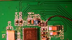
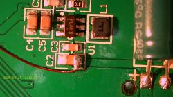
    The ADC is normally not connected (R7 & R8), and from the origin PCB design only measurement to regulated 3,3V power supply is possible. The step-up voltage converter includes an undervoltage detection to switch off in emergency (empty or removed battery). A big 470 microfarad buffer capacitor on battery side is equipped, too.

    Close-up of a green printed circuit board with SMD electronic components, traces, and a soldered red wire.
    Close-up of a PCB section with SMD electronic components.


    Greetings Thomas
  • #25 21525710
    insmod
    Level 23  
    >>21525678
    You don't need to flash back, just disabling flag 51 would do.
    You also need to wait at least ten seconds while connected to fast connect data to be saved. If not - then it connects normally.
    It's a random thing, on some of my devices it doesn't work properly too.
    I remember that my T device only connected on the second try, but after i rebooted my router (AX3600 OpenWrt 24.10), it started connecting on the first try.

    I also recommend to quickly reset 3 times with flag 51 enabled to erase fast connect data - to ensure that it didn't try to use some garbage data.
  • #26 21525724
    pirkelt
    Level 3  
    Thanks a lot for your very fast reply!

    I will try it again and will report later!

    Cheers Thomas
  • #27 21526411
    pirkelt
    Level 3  
    Hello all, Hello @insmod,

    back from my family I tried your recommendations and tested again. Disabling flag 51 decreases the connection time to 4-6 seconds. Similar to 18.76 FW. My Router is a AVM FB 7590. It looks like the Unit starts two times with two instances. Both count down timers are visible in Web UI. Old 18.76 FW shows only one and for my opinion is correct. This behaviour is repeatable. Can this be explained?


    Ledvance_Remote control panel interface with buttons and battery, MQTT status information.

    here is my log from beginning with one switching event:

    N:Time 13, idle 191192/s, free 67368, MQTT 0(1), bWifi 1, secondsWithNoPing -1, socks 2/38
    Info:MAIN:Time 14, idle 190262/s, free 67368, MQTT 0(1), bWifi 1, secondsWithNoPing -1, socks 2/38
    Info:MAIN:Time 15, idle 176496/s, free 67368, MQTT 0(1), bWifi 1, secondsWithNoPing -1, socks 2/38
    Info:MAIN:Time 16, idle 192364/s, free 67368, MQTT 0(1), bWifi 1, secondsWithNoPing -1, socks 2/38
    Info:MAIN:Time 17, idle 189727/s, free 67368, MQTT 0(1), bWifi 1, secondsWithNoPing -1, socks 2/38
    Info:MAIN:Time 18, idle 189450/s, free 67368, MQTT 0(1), bWifi 1, secondsWithNoPing -1, socks 2/38
    Info:MAIN:Time 19, idle 191961/s, free 67368, MQTT 0(1), bWifi 1, secondsWithNoPing -1, socks 2/38
    Info:MAIN:Time 20, idle 189475/s, free 67368, MQTT 0(1), bWifi 1, secondsWithNoPing -1, socks 2/38
    Info:GEN:dhcp=0 ip=192.168.0.80 gate=192.168.0.8 mask=255.255.255.0 mac=4c:a9:19:4c:23:eb
    Info:GEN:sta: 1, softap: 0, b/g/n
    Info:GEN:sta:rssi=-49,ssid=xxxxxxxxx ,bssid= xx:xx:xx:xx:,channel=6,cipher_type:CCMP
    Info:MAIN:Time 21, idle 184448/s, free 67368, MQTT 0(1), bWifi 1, secondsWithNoPing -1, socks 2/38
    Info:MQTT:mqtt_host empty, not starting mqtt
    Info:MAIN:Time 22, idle 192064/s, free 67368, MQTT 0(2), bWifi 1, secondsWithNoPing -1, socks 2/38
    Info:MAIN:Time 23, idle 188849/s, free 55672, MQTT 0(2), bWifi 1, secondsWithNoPing -1, socks 3/38
    Info:MAIN:Time 24, idle 188127/s, free 67368, MQTT 0(2), bWifi 1, secondsWithNoPing -1, socks 2/38
    Info:GEN:15 Button_OnInitialPressDown
    Info:GEN:15 key_short_press
    Info:EVENT:EventHandlers_FireEvent: executing command backlog SendGet http://192.168.0.47/rpc/Switch.Toggle?id=1 // P15 LED (A2) schalten
    Info:CMD: CMD_SendGET received with args http://192.168.0.47/rpc/Switch.Toggle?id=1 // P15 LED (A2) schalten
    Info:HTTP_CLIENT:HTTPClient_Async_SendGet for http://192.168.0.47/rpc/Switch.Toggle?id=1, sizeof(httprequest_t) == 160!
    Info:MQTT:Channel has changed! Publishing 1 to channel 6
    Info:HTTP_CLIENT:Parse url http://192.168.0.47/rpc/Switch.Toggle?id=1
    Info:HTTP_CLIENT:host: '192.168.0.47', port: 80
    Info:HTTP_CLIENT:HAL_TCP_Establish: created socket 2

    Error:HTTP_CLIENT:success to establish tcp, fd=2
    Info:HTTP_CLIENT:httpclient_recv 131 bytes has been read
    Info:CMD:LFS_ReadFile: failed to file //
    Info:MAIN:Time 25, idle 178350/s, free 67368, MQTT 0(2), bWifi 1, secondsWithNoPing -1, socks 2/38
    Info:MAIN:Time 26, idle 188174/s, free 67368, MQTT 0(2), bWifi 1, secondsWithNoPing -1, socks 2/38


    Thanks for your attention,

    Thomas
  • #28 21527508
    gelbetomate
    Level 3  
    Hi,

    I thought it's because of me still struggling with the setup, but now it looks like it's not only at my place. I can confirm with the same router type it looks the same here:

    Screenshot of Ledvance Remote Control 1 dashboard showing button status, battery level, chip temperature, and configuration options.

    Also the logs have those entries.

    It connects, the wifi light flashes, then it stays connected, until the 2nd sleep timer went down to 0, then the light flashes (connects) again and after the next deep sleep timer went down the light turns off completely and the connection is lost. Only turning power off and on brings it back to life. I didn't solder anything with the voltage regulator or any shunt etc. and I'm still powering my remote with 3.3V from the USB TTL converter.

    Cheers

Topic summary

The discussion revolves around the Ledvance Sun@Home Planon Plus and its remote control, which utilizes a BK7231N chip. The user seeks to flash the remote with OpenBeken firmware without soldering, as the chip is too small for conventional soldering techniques. Initial responses suggest that soldering to available pads is necessary, and the user confirms they can solder. However, they encounter issues with reading the flash due to incorrect TX/RX connections and the need for a common ground. After multiple attempts, the user discovers that the TX and RX pads are mislabeled, complicating the flashing process. Eventually, the user gives up due to damaged pads but identifies the remote's button matrix configuration, indicating a potential for programming support. A developer offers assistance in creating a driver for the matrix keyboard functionality, suggesting collaboration on the code.
Summary generated by the language model.
ADVERTISEMENT