I'm looking for some ideas for setting up some sort of 'system' to detect the status of overcurrent/differential current protection in a domestic switchboard. Has anyone come across something like this or maybe they have done it themselves? I mean, without looking into the distribution board, I would like to know which protections are switched on and which are switched off, on which there is voltage and on which there is no voltage.
Generally a seemingly simple matter, unfortunately there is one "but", i.e. 230VAC. I guess the only solution (apart from using special protections with auxiliary contacts) is to screw an additional control wire to each protection under each contact.
The first problem is screwing two wires of different cross-sections onto one contact. I looked to see if there were any "sleeves" something a bit like male car connectors, i.e. something that would have a large flat surface, preferably the size of the contact area in the protection - unfortunately I could not find anything like that. In some protections it would probably be possible to use fork connectors under the screw in the place where the busbars are used, but in my switchgear there are Siemens protections and they do not have this possibility.
The second problem is the voltage of 230VAC, how to check here in a simple and safe way whether there is voltage and preferably what is the voltage and whether there is a connection between the input and output contact (whether the protection is on or off)?
In general I would like to measure the voltage at the input and at the output and whether there is a "transition" between input and output, i.e. whether the protection is on.
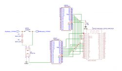
As far as the transition detection is concerned, I came up with something like the diagram below "just in the nick of time".
 .
.
Generally a seemingly simple matter, unfortunately there is one "but", i.e. 230VAC. I guess the only solution (apart from using special protections with auxiliary contacts) is to screw an additional control wire to each protection under each contact.
The first problem is screwing two wires of different cross-sections onto one contact. I looked to see if there were any "sleeves" something a bit like male car connectors, i.e. something that would have a large flat surface, preferably the size of the contact area in the protection - unfortunately I could not find anything like that. In some protections it would probably be possible to use fork connectors under the screw in the place where the busbars are used, but in my switchgear there are Siemens protections and they do not have this possibility.
The second problem is the voltage of 230VAC, how to check here in a simple and safe way whether there is voltage and preferably what is the voltage and whether there is a connection between the input and output contact (whether the protection is on or off)?
In general I would like to measure the voltage at the input and at the output and whether there is a "transition" between input and output, i.e. whether the protection is on.
As far as the transition detection is concerned, I came up with something like the diagram below "just in the nick of time".
 .
.


