logo elektroda
logo elektroda
X
logo elektroda

DIY magnetic stirrer: problems with Wemos D1 Mini, motor and DS18B20 thermometers

zendev 294 10
ADVERTISEMENT
Treść została przetłumaczona polish » english Zobacz oryginalną wersję tematu
  • #1 21367506
    zendev
    Level 5  
    Hi,

    As a weekend hobby and to learn electronics, I decided to make a magnetic stirrer for yeast propagation.
    The stirrer is to have motor speed control, speed measurement (as a fun addition), temperature measurement (ambient and liquid), cooling and heating control (relays) and in the future a touch screen (2,8" ILI9341).

    Components
    - The heart of the circuit is a Wemos D1 Mini (lion clone).
    - For the power supply, I used a JustPi 5v/2.5A power supply. Connected to it was a 5A version of the LM2596 twisted to 3.3V.
    - The motor is an rs550vs and is powered by 12v as standard. As it doesn't need that much RPM and torque I am powering it with 5v.
    - The motor controller is: TB6612FNG. It uses one channel.
    - I use a TCRT5000 LM393 reflection module to measure the speed.
    - The relay module is a standard board with 2 relays from an arduino. As wemos operates on 3.3v and the relays on 5v, the board itself is additionally connected under 5v (instead of a jumper)
    - The thermometers are standard ds18b20 with a 4.7k pull-up resistor
    - I based the software on esphome. Easy configuration and integration with other software.

    In theory, the circuit works fine. However, I have a few problems with it:
    - after connecting the power supply, the motor always turns (about 1/2-1 turn) and only stops
    - wemos does not always detect connected thermometers
    - after connecting the thermometers the system resets. motor turns over, wemos starts from the beginning.
    The starting action is so "painful" that I finally damaged the wemos in the tests.

    What could be wrong? Which components in particular should I pay attention to for diagnostics?
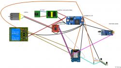
    Electronic schematic of a magnetic stirrer using Wemos D1 Mini and other components .

    Many thanks in advance for your help! and apologies for the large number of connections in the picture :(

    btw. once I have stabilised the solution I will want to add a touch screen to manage the whole thing safely.
    Do you have a problem with Arduino? Ask question. Visit our forum Arduino.
  • ADVERTISEMENT
  • #2 21367521
    drunek
    Level 25  
    Show the source code of the microcontroller.
  • #3 21367537
    johny_w
    Level 24  
    zendev wrote:
    after power is applied, the motor will always turn (about 1/2-1 turn) and only stall
    .
    This could be a transient (or fixed on) of some motor control line. Before the mcu starts the driver gets a signal.
    What control lines do you have connected to the motor driver?
  • ADVERTISEMENT
  • #4 21367557
    zendev
    Level 5  
    >>21367521 I have a configuration file in esphome:

    substitutions:
      friendly_name: "Mieszadło"
    
    esphome:
      name: beer-magnetic
      friendly_name: ${friendly_name}
      area: Beer
    
    esp8266:
      board: d1_mini_lite
    
    # Enable logging
    logger:
    
    # Enable Home Assistant API
    api:
      encryption:
        key: "#"
    
    ota:
      - platform: esphome
        password: "#"
    
    wifi:
      ssid: !secret wifi_ssid
      password: !secret wifi_password
    
      # Enable fallback hotspot (captive portal) in case wifi connection fails
      ap:
        ssid: "Beer-Magnetic Fallback Hotspot"
        password: "#"
    
    captive_portal:
      
    # motor v2
    output:
      - platform: gpio
        id: motor_forward
        pin: D7 # Pin to IN1
      - platform: gpio
        id: motor_reverse
        pin: D8  # Pin to IN2
      - platform: esp8266_pwm
        pin: D6   # Pin to PWM
        id: motor_speed
        frequency: 20000Hz
    
    number:
      - platform: template
        name: magnetic_motor
        id: motor_controll
        min_value: 0
        max_value: 35
        step: 5
        optimistic: true
        initial_value: 0
        on_value:
           then:
              - lambda: |- 
                      if (id(motor_controll).state == 0) {
                        id(motor_speed).set_level(0.0);
                        id(motor_forward).turn_off();
                        id(motor_reverse).turn_off();
                      } else {
                        if (id(motor_controll).state < 0) {
                          id(motor_speed).set_level((id(motor_controll).state *-1)/100);
                          id(motor_forward).turn_on();
                          id(motor_reverse).turn_off();
                        } else {
                          id(motor_speed).set_level((id(motor_controll).state)/100);
                          id(motor_forward).turn_off();
                          id(motor_reverse).turn_on();
                        }
                      }
    # motor v2 - eof
    
    # relays
    switch:
      - platform: gpio
        pin: D0
        name: "Grzanie"
        id: heater
        inverted: True
      - platform: gpio
        # pin: D3
        pin: TX
        id: cooler
        name: "Chłodzenie"
        inverted: True
      - platform: gpio
        pin: D3
        id: motor_on_off
        name: "Motor on/off"
        restore_mode: ALWAYS_OFF
    # relays eof
    
    # temp - 1
    one_wire:
      - platform: gpio
        pin:
          number: D4
        id: temperature
    # temp eof - 1
    
    sensor:
    # tacho
      - platform: pulse_counter
        pin: 
          number: D5
          # mode:
            # input: true
            # pullup: true
        id: motor_rpm
        unit_of_measurement: 'RPM'
        name: "Motor RPM"
        accuracy_decimals: 0
        filters:
          - lambda: return x / 4;
        update_interval: 5s
    # tacho eof
    # temp - 2
      - platform: dallas_temp
        one_wire_id: temperature
        address: 0xd400000f89557028
        name: water
        id: water
        device_class: "temperature"
        state_class: "measurement"
        accuracy_decimals: 2
        update_interval: 30s
        filters:
          - round_to_multiple_of: 0.25
          - heartbeat: 5s
      - platform: dallas_temp
        one_wire_id: temperature
        address: 0x6607237004a3d128
        name: case
        device_class: "temperature"
        state_class: "measurement"
        accuracy_decimals: 2
        update_interval: 30s
        filters:
          - round_to_multiple_of: 0.25
          - heartbeat: 5s
    # temp eof - 2
    
    # thermostat
    climate:
      - platform: thermostat
        name: "Kolba"
        sensor: water
        min_cooling_off_time: 30s
        min_cooling_run_time: 30s
        min_heating_off_time: 30s
        min_heating_run_time: 30s
        min_idle_time: 30s
        cool_action:
          - switch.turn_on: cooler
        heat_action:
          - switch.turn_on: heater
        idle_action:
          - switch.turn_off: cooler
          - switch.turn_off: heater
        default_preset: Home
        preset:
          - name: Home
            default_target_temperature_low: 20.0 °C
            default_target_temperature_high: 21.0 °C
    # thermostat eof
    .

    Based on this, the system generates the code. I can download the ELF file if that helps anything.

    >>21367537 the controller is wired to wemos according to the schematic:
    AIN1 - D7
    AIN2 - D8
    PWM A - D6 and frequency 20000Hz
    STSY - D3. It defaults to ALLWAYS_OFF (low state). It probably only turns on when Wemos is started. Maybe this pin needs to be pulled up in some way?


    I also have a suspicion that the 5v/2.5A power supply is not too weak and thus the circuit does not read the thermometers and goes crazy when plugged in. Do you think this is possible?
  • #5 21367598
    johny_w
    Level 24  
    In the diagram you don't have the vcc connected to the driver, is that really the case?
    Isn't this motor on 12v (you are feeding 5v to the VM).

    Also do a test - unplug the STBY from the driver and see if the motor then starts too when you power it up.
  • ADVERTISEMENT
  • #6 21367773
    zendev
    Level 5  
    >>21367598 VCC is not connected to the driver. I missed while soldering. I will correct it. Mega thanks.

    The motor has a nominal 12V. Its power at 12v is way too strong. Already at 5V it runs at 30-35%. I therefore decided to power it with a lower voltage. I had it at a very good price, so I applied it.

    I will add VCC and test the STBY disconnection.

    Still additional questions:
    - should I connect the grounds from the 5V and 3.3V circuit and treat them separately or together?
    - can I solder the pull-up resistor on the DS18B20 to the feet of the first thermometer, or should that be closer to the Wemos?
    - for testing the power supply performance, can I supply the chip with LM2596 3.3V and the Wemos USB supply at the same time, or is it better not to do this?
  • ADVERTISEMENT
  • #7 21367786
    drunek
    Level 25  
    You should not supply the motor with more than twice the rated voltage, but use PWM instead.
    zendev wrote:
    should I connect the grounds from the 5v and 3.3v circuit and treat them separately or together?
    .
    They are connected anyway, this inverter module has no separation between input and output, - the ground is common.
  • #8 21368121
    kmarkot
    Level 29  
    I would use 5V to power the wemos D1 while I would use 3.3V from the wemos to power the ds18b20. So the LM2596 is unnecessary.

    I have Dalybms supported by ESP8266 powered by 3.3V there is information about low supply voltage .

    Low ESP voltage notification on Daly2MQTT interface .
  • #9 21368238
    zendev
    Level 5  
    >>21368121 to supply 3.3v in addition to the ds18b20 there is also a bounce sensor, motor controller and in the future a touchscreen. wemos will hold this?

    better to connect wemos via usb connector or goldpin 5v?
  • #10 21368280
    kmarkot
    Level 29  
    I have some ESPs powered via USB, also via goldpins, and I don't see any difference.
    So how are you more comfortable.
  • #11 21380366
    zendev
    Level 5  
    i have made the following changes to the circuit:
    - I removed the LM2596. i supply the wemos directly from 5v. I supply the rest of the hardware with 3.3v from the wemos
    - I installed the missing 3.3v to the motor driver.

    After the change the reading from the d218b20 improved. Now they no longer drop out and are available all the time.

    Unfortunately the errors are still there: engine rotation after system start, system restart after attaching/detaching ds18b20 sensor.

    As a test, I installed 10k and then 4.7k resistors between the standby and gnd legs of the motor controller. Unfortunately, such pull-ups also did nothing.

Topic summary

A DIY magnetic stirrer project using a Wemos D1 Mini (ESP8266) as the main controller integrates motor speed control, speed measurement via a TCRT5000 LM393 reflection sensor, temperature monitoring with DS18B20 sensors, and relay-based cooling/heating control. The motor is an RS550VS, originally 12V but powered at 5V for reduced speed and torque, controlled by a TB6612FNG motor driver. Initial issues included the motor running unexpectedly at system start and system resets triggered by attaching/detaching DS18B20 sensors. A missing VCC connection to the motor driver was identified and corrected. Power supply design evolved from using a JustPi 5V/2.5A supply with an LM2596 step-down to directly powering the Wemos at 5V and peripherals at 3.3V from the Wemos, improving DS18B20 sensor stability. Ground lines for 3.3V and 5V circuits are common. Pull-up resistors for DS18B20 can be soldered near the first sensor or closer to the Wemos. Tests with pull-up resistors on the motor driver's standby pin did not resolve motor startup issues. Powering the Wemos via USB or 5V goldpin showed no significant difference. The project plans to add a 2.8" ILI9341 touchscreen in the future.
Summary generated by the language model.
ADVERTISEMENT