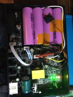
On my estate, the biggest problem is the frequent lack of electricity. The situation repeats itself almost every week and this occurs for several hours. I don't know the reasons - there is construction going on around here and maybe there is an interruption when connecting new buildings. Fortunately, the laptop battery, despite its age, still provides support, so I could work in peace, but I don't have internet at the time, as the modem is powered from the mains.
.
Design of emergency power supply for router or modem .
On behalf of a client, I developed an uninterruptible power supply (UPS) for an alarm system installed in a garage where power interruptions are constant. This UPS contains a charging circuit for two or three Li-Ion cells, a DC-DC converter from 3.7 to 12V. And it can be used as an emergency power source for a modem or router. For this reason, I have decided to share this project.
.
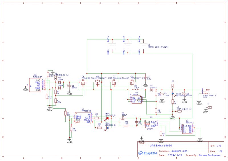
This first one is made on a TP4056 IC and FS3401 field effect transistors. The cell temperature sensor is not used in this case. The LEDs LED1-2 show the status: red - charging, green - its end. The specialised DW01A circuit, which controls a pair of FS8205A field-effect transistors, is responsible for overcharging protection. These are connected between the minus of the battery and the ground of the device.
.
The DC-DC converter from 3.7-5 to 12V is made on the MT3608B chip. It is powered from a USB port from a regular charger, providing a current of no less than 1A, or from 18650 batteries connected in parallel when there is no voltage from the charger. The output voltage can be adjusted by changing the value of resistors R8-R9.
I had to create this schematic from photos of a ready-made Chinese instrument as part of Reverse Engineering. The circuit board, on the other hand, I developed myself. It is dedicated for a socket for 2 or 3 cells. If a socket for 2 is used, part of the board can easily be cut off. Surface mount, but due to the larger size SMD components used, they can be soldered by hand. Circuits (wires), transmitting high current, should be strengthened with a thick layer of solder.
The board can be made yourself or ordered from Chinese factories using the files I have attached below.
.
Emergency power supply diagram
Design of emergency power supply for router or modem .
On behalf of a client, I developed an uninterruptible power supply (UPS) for an alarm system installed in a garage where power interruptions are constant. This UPS contains a charging circuit for two or three Li-Ion cells, a DC-DC converter from 3.7 to 12V. And it can be used as an emergency power source for a modem or router. For this reason, I have decided to share this project.
.
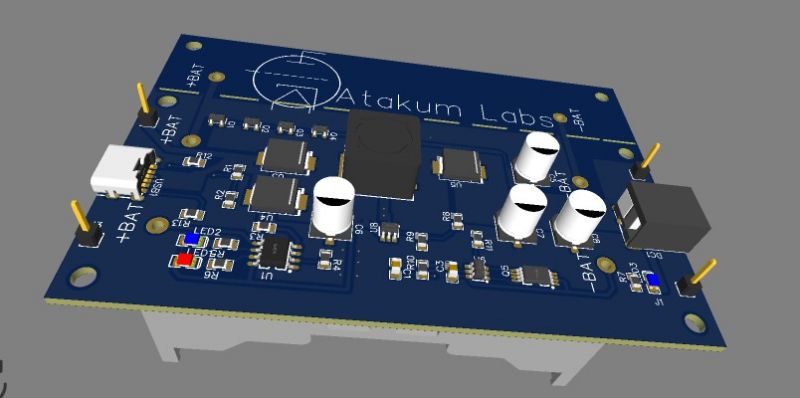
View of plate from top
This first one is made on a TP4056 IC and FS3401 field effect transistors. The cell temperature sensor is not used in this case. The LEDs LED1-2 show the status: red - charging, green - its end. The specialised DW01A circuit, which controls a pair of FS8205A field-effect transistors, is responsible for overcharging protection. These are connected between the minus of the battery and the ground of the device.
.
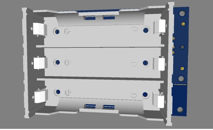
View from below
The DC-DC converter from 3.7-5 to 12V is made on the MT3608B chip. It is powered from a USB port from a regular charger, providing a current of no less than 1A, or from 18650 batteries connected in parallel when there is no voltage from the charger. The output voltage can be adjusted by changing the value of resistors R8-R9.
I had to create this schematic from photos of a ready-made Chinese instrument as part of Reverse Engineering. The circuit board, on the other hand, I developed myself. It is dedicated for a socket for 2 or 3 cells. If a socket for 2 is used, part of the board can easily be cut off. Surface mount, but due to the larger size SMD components used, they can be soldered by hand. Circuits (wires), transmitting high current, should be strengthened with a thick layer of solder.
The board can be made yourself or ordered from Chinese factories using the files I have attached below.
Cool? Ranking DIY


