logo elektroda
logo elektroda
X
logo elektroda

Remote controlled tank/car (via WiFi), chassis with tracks, L298 module with NodeMCU

p.kaczmarek2 2100 25
ADVERTISEMENT
Treść została przetłumaczona polish » english Zobacz oryginalną wersję tematu
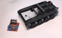
  • Tracked robot model next to L298 module. .
    How to build a robot on a NodeMCU, L298 and two motors? Here is a short mini-project - part one. We are running a remote controlled "tank" with two tracks. By the way, we will see how to connect the L298 to the motors, how to operate it with PlatformIO/Arduino and how it can be controlled via WiFi. The method shown here, however, will also be able to work just as well for the typical 2wd robot chassis available to buy online....
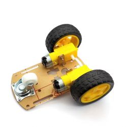
    Robot chassis module with two yellow motors and attached wheels. .
    I will show the whole thing step by step so that a beginner can follow what I was running and how. In addition, I will try to simplify so that the project is not too demanding and complicated. The project will be divided into at least several parts, where I will gradually present the progress, solutions and problems encountered.

    At this stage, I'm assuming that this is a toy that is, to put it jokingly, 'not going out' or 'home' - that is, it will work with our WiFi and will pair with it via WiFiManager. At a later stage I may change this assumption too.

    NodeMCU .
    NodeMCU is such an "Arduino of the new times" for me. Cheap, useful, convenient, supported by many libraries. The NodeMCU is based on the ESP8266 and offers, among other things, connectivity via WiFi.
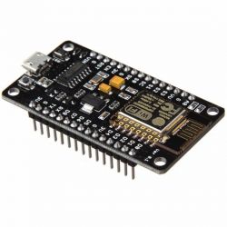
    NodeMCU board with ESP8266 microcontroller. .
    In addition, there is a USB to UART converter on board to facilitate easy wired programming (although you can also change the batch over WiFi) and a 3.3V LDO regulator to ensure a stable 3.3V for the ESP with 5V from USB.
    I program the whole thing in PlatformIO, this has already been discussed:
    Clock on ESP12 and MAX7219 display - tutorial - part 1, ArduinoOTA, basics .
    WiFi Manager in PlatformIO - convenient WiFi configuration for ESP8266 and ESP32 - tutorial

    Chassis module .
    I bought the chassis module in China. I'm not sure if it has a model name by which it can be found, but basically the whole tutorial can be done on any module with tracks, or even with regular wheels. It's just important to choose the right module to control the motors - you need to respect the maximum operating voltage and current.
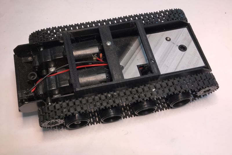
    Robot chassis with tracks and two motors. .
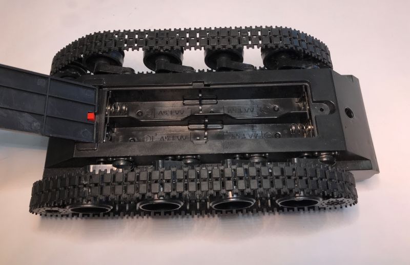
    My module has space for 4 AA batteries on the bottom:
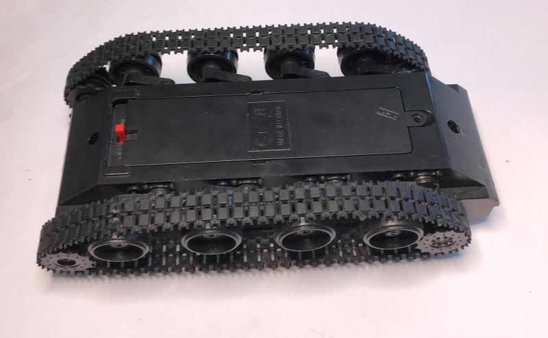
    Robot chassis with tracks and battery compartment .
    View of a robot chassis with tracks and AA battery compartment. .
    These batteries are nominally 1.5V, so 4*1.5V = 6V, but in practice as they discharge the voltage will drop. This is something to watch out for, because if we power a NodeMCU from them with an LDO AMS1117-3.3V regulator on board, the voltage at its input must be at least around 4.6V (according to the datasheet note) to get a stable output....


    L298N module .
    I bought the module with the L298N from an importer in our country for a dozen zlotys, although it can be imported cheaper.
    The L298N is a dual motor controller operating at up to 46V and up to 4A current. Two motors can be connected to it, each motor being controlled independently.
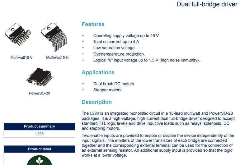
    Technical specification page for the L298 chip with package drawings and list of features. .
    There are 3 control pins per motor, one enable pin and two in. In addition, two supply voltages are applied separately to L298N, one for the motors (up to 46V) and the other up to 7V (logic):
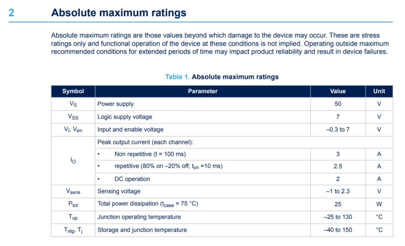
    Table with maximum ratings for L298 parameters. .
    To control the motor we need to:
    - connect the PWM to EN - this will determine the speed of the motor, although at lower PWM settings the motor will not start, it will only "buzz"
    - connect the logic pins to IN1 and IN2; manipulation of these pins will allow us to change the direction of the motor or activate braking
    The specific settings are shown in the truth table:
    IN1 IN2 . Result
    high low motor on (speed is determined by PWM on EN)
    low high motor on -. reversing (speed is determined by PWM on EN)
    low low fast braking of motors (when high state on EN)
    high high fast braking of motors (when low on EN)
    high high free braking of the motors (when there is a high state on the EN)
    .
    Two PWM and four digital pins are therefore required for two motors.

    The commercially available L298 module is essentially L298 + 5V stabiliser. In this situation, we can specify with a jumper whether we want to give, for example, 9V inputs of our own and draw current from the 5V, or whether the stabiliser can be switched off. This is determined by the schematic:
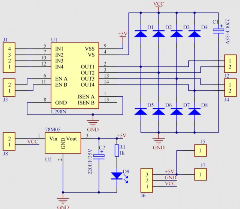
    L298N wiring schematic with motors. .
    There are two potential pitfalls here, however:
    - The 7805 has slightly lower maximum input voltages than the L298N, plus it heats up at higher voltages, so in such situations consider using, for example, an external step-down converter
    - if we give 5V to the input, the 7805 will not switch on (at least when I tested it, it gave 0.5V at the output...) so then you can power both sides, the motors and the logic one with 5V

    First connection .
    In the end, I opted for absolute minimalism. I connect the batteries directly to the L298 module and additionally on Vin from the NodeMCU, as their voltage is within the operating range of the AMS1117-3.3V present on this board. The 7805 on L298 is omitted, with power being routed to both sides from Vin.
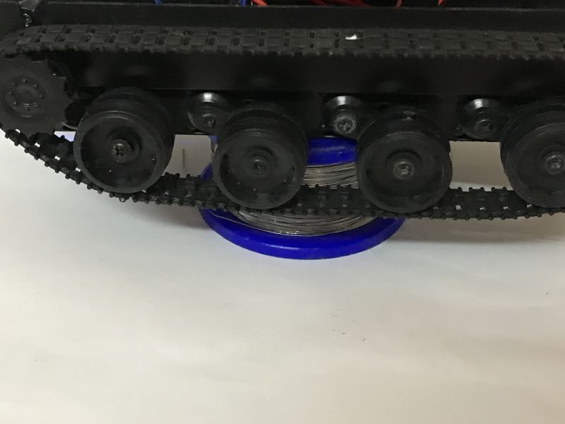
    In addition, as a test, I put the whole thing on a spool from the solder joint so that the tracks do not touch the ground, so the vehicle will not run away while I am writing the programme.
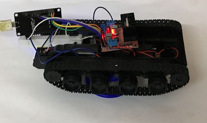
    Tank-style robot built on a NodeMCU platform with a track chassis. .
    Robot chassis with tracks on a spool. .

    Beginning program - ArduinoOTA and WiFiManager .
    I write my ESP programs in PlatformIO (an environment based on Visual Code) and I highly recommend its use. I usually start my adventures the same way - my initial program includes two useful libraries that I have already discussed:
    - WiFi Manager - for pairing with WiFi
    - ArduinoOTA - to update the batch remotely
    The program basically contains only the basic integration of these two libraries enriched additionally with a flashing diode which is on the WiFi module itself. During configuration (blocking call from WiFiManager) the diode does not flash, only during normal operation.
    Code: C / C++
    Log in, to see the code
    .


    Add a server (to receive commands) .
    Let's start with communication. The easiest way is to add a simple HTTP server. Admittedly, TCP is connection-intensive and can introduce minor delays when a packet retransmission occurs, but that is negligible here.
    The creation of the server comes down to the use of the ESP8266WebServer class, or more precisely to the creation of an object of this class, where the only argument of the constructor is the port we are listening on. Then, using the "on" function, we set the functions that handle the given resource from the server, in my case there is only one, the "hello world" page. Then we start the server (function begin):
    Code: C / C++
    Log in, to see the code
    .
    Result:
    Screenshot of a webpage at IP address 192.168.0.109 displaying the text Hello, World! .

    Add a simple control via HTTP .
    The control will come in handy smoothly, in addition to having to take into account both directions of the motor. For this reason I decided to use a slider from HTML. You can easily set a range for it - say from -100 to 100. 0 is no movement, -100 is counterclockwise and 100 is clockwise, all the way forward.
    Additionally, as a simplification, instead of pasting my code over and over into PlatformIO, I just ran it on the computer.... .
    This simplifies the process of testing and creating the page.
    So, the current code:
    Code: HTML, XML
    Log in, to see the code
    .
    Result:
    Robot control interface with slider and value 49 .
    In addition, you still need to send the slider value to the NodeMCU. All you need for this is a short script - addEventListener, input event:
    Code: HTML, XML
    Log in, to see the code
    .
    The fetch function sends a GET request to /steer whose argument is a value with a value from the slider. This now needs to be received and handled.
    I have introduced endpoint in the project:
    Code: C / C++
    Log in, to see the code
    .
    And then in it I added control handling:
    Code: C / C++
    Log in, to see the code
    .
    I use hasArg to check if an argument is available, and retrieve it with the arg function. Then I do what was mentioned for L298 - I set the direction pins and the PWM value (two digital pins - digitalWrite and one PWM - analogWrite). I decode the negative value to the direction and then write it already without a sign so that I can send it to the PWM.
    The rest of the code:
    Code: C / C++
    Log in, to see the code
    .
    Video of the track movement:


    Class of tracks .
    There are two caterpillars, so it is tempting to separate their code into a separate class. This will allow more convenient development and maintenance of the project.
    I packed the whole thing into the Track class. This class stores the pins for controlling one motor, its enable pin and two directional pins.
    Code: C / C++
    Log in, to see the code
    .
    The rest of the code:
    Code: C / C++
    Log in, to see the code
    .
    It is now convenient to create two extinguishers:
    Code: C / C++
    Log in, to see the code
    .
    As a test, I do not yet separate the values sent by the web page, I simply enter it into both crawlers:
    Code: C / C++
    Log in, to see the code
    .


    Separating the tracks .
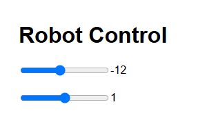
    I didn't want to complicate things, so I essentially copied the slider so that there are now two. One each for the tracks.
    Code: HTML, XML
    Log in, to see the code
    .
    The result:
    Two sliders for controlling a robot. .
    I organised the script in turn so that the data is sent together - there is one change event handler for both sliders and it sends one common GET request:
    Code: HTML, XML
    Log in, to see the code
    .
    Now on the ESP, in handleSteer, I can separately access each of the arguments:
    Code: C / C++
    Log in, to see the code
    .
    In this way, we can remotely control each track separately.

    First drives .
    At this stage, you can already drive. Let's see how the tank performs.


    .
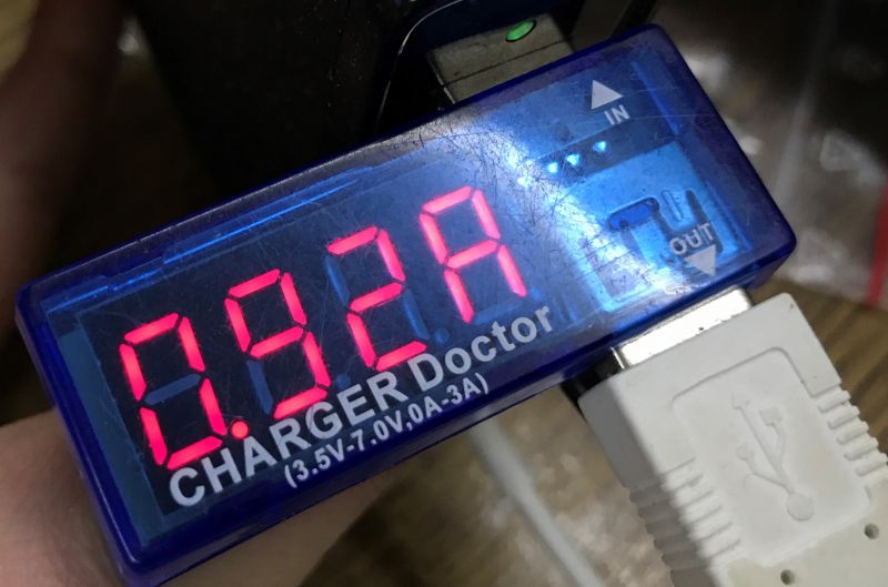
    The chassis works, but rides rather sluggishly in places. I measured the current consumption, first of one motor and then of the whole (NodeMCU + 2 motors) when powered by USB:
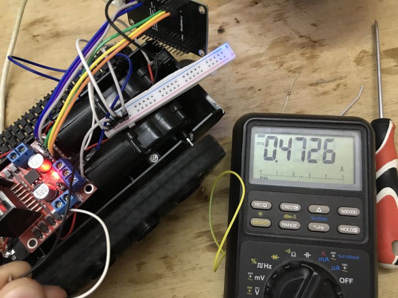
    Current measurement in a robot built with L298 and NodeMCU modules .
    Display of a measuring device showing 0.92 A. .
    In addition, I saw that even with the USB wired power supply the voltage drop is noticeable - with one motor it is able to drop to almost 4V, and with both even lower.
    I tested the option with a powerbank for this reason:
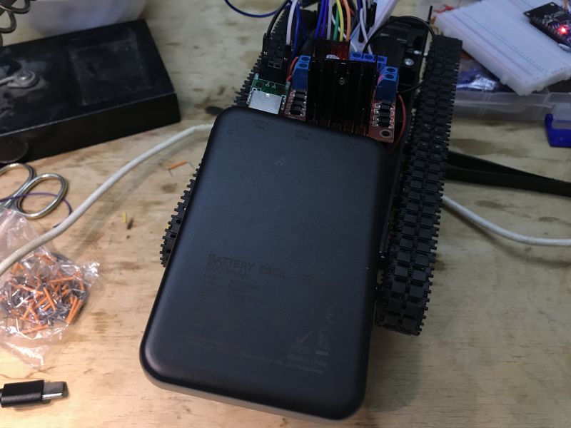
    Tracked vehicle with electronic components and a power bank. .
    It is better - with both motors at full power it drops to 4.2V:
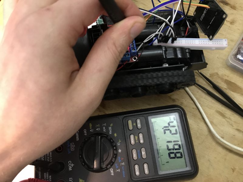
    Hand measuring voltage with multimeter on track robot .
    The ride is better:


    .
    I'm staying with the powerbank for the moment.

    Summary .
    This was the first step of work on our car. Here we managed to run a comfortable working environment based on NodeMCU programmed remotely (OTA, via WiFi) in PlatformIO and then drive the motors from it via a module from L298. The power supply was finally realised using a powerbank, which nevertheless holds its own and can be driven in comfort. I rejected the idea of AA batteries, as they heat up, the voltage drops (more so than with the powerbank) and it's a shame to use them up..
    On the programming side it was just as simple as on the hardware side - there is one PWM per motor and two digital pins, this allows it to be controlled both ways. We separated the motor operation into a separate class so that we could have two motors (or tracks) and then controlled them in the simplest way via an HTTP server - GET request arguments.
    The project works but leaves a lot to be desired, even the control is clumsy.
    For this reason, I will introduce a virtual joypad in the next section:
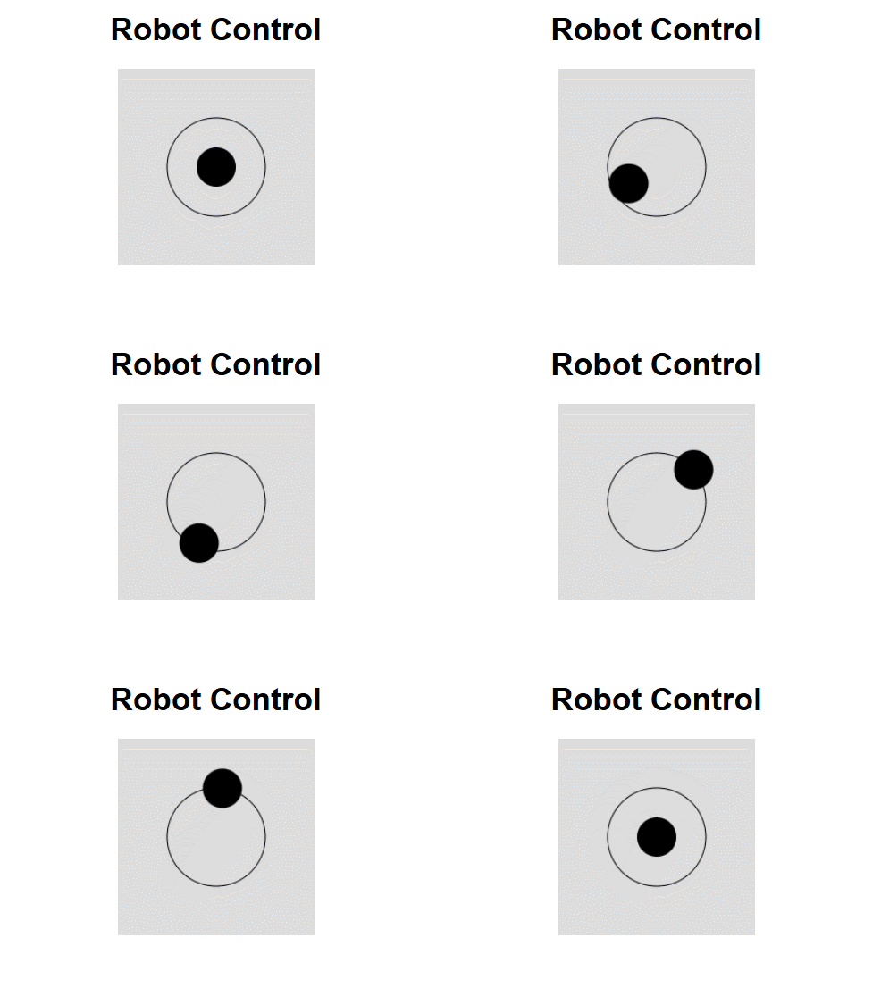
    Robot control interface with virtual joystick. .
    All in all, I am planning at least several parts, where with each part improvements, modifications and problems encountered will be presented.
    It went exceptionally smoothly at this point - I was expecting trouble with the ESP power supply, but it didn't reset once for me. The biggest hassle was battery power, but I just skipped that - the powerbank fit just fine.
    Feel free to comment - maybe you have some ideas on what to implement next? I already have a bit of sensors lined up myself, as well as a 3D printer ready to help improve the build of the car, and the ESP32-cam module will also be somewhere... .
    PS: Attached the same code in as in the post, but together in one file. Final version.
    Attachments:

    Cool? Ranking DIY
    Helpful post? Buy me a coffee.
    Do you have a problem with Arduino? Ask question. Visit our forum Arduino.
    About Author
    p.kaczmarek2
    Moderator Smart Home
    Offline 
    p.kaczmarek2 wrote 11838 posts with rating 9933, helped 566 times. Been with us since 2014 year.
  • ADVERTISEMENT
  • #2 21450587
    TechEkspert
    Editor
    Leaving such a driving platform with a camera and charging station at home is a nice idea for video monitoring of the house when we are on a trip.
    In a more advanced version, such a platform could make its own rounds, or rather detours, and report anomalies or send a video of the ride to a server.
  • ADVERTISEMENT
  • #3 21450611
    p.kaczmarek2
    Moderator Smart Home
    Last year I was thinking of redoing the cleaning robot, maybe replacing its 'brain' with a Raspberry, and I already had two robots set aside.... but unfortunately they both drowned in the flood and all I had left was just this toy tank chassis, because unfortunately after losing a couple of rooms I was forced with, I estimate, 100kg of mucked up hardware.... only the photo remains:
    Toy tank chassis and electronic components in a cardboard box. .
    But maybe in which part I will think about a charging station.
    Helpful post? Buy me a coffee.
  • ADVERTISEMENT
  • #4 21450814
    TechEkspert
    Editor
    Perhaps a contactless charging station? Less problems with positioning.
  • #5 21450894
    XMarian
    Level 10  
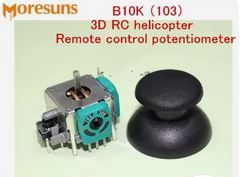
    A remote control with 2 potentiometers, so called analogue console pads, would suit this project perfectly. Print out a casing with a place for a phone (to view the image from the camera) and we would have control just like in a real tank.
    The speed of the motors is regulated by tilting a potentiometer and each track is controlled by one pad.
    The potentiometers also include microswitches, which can be used for additional functions, e.g. switching on lighting and the camera, and we have a usable vehicle for exploring the underground.
    Ready-made modules for transmitting the image from the camera to the phone via wifi are available from the Chinese, so this should not complicate the project very much.

    Remote control potentiometer and black pad. .
  • #6 21450909
    p.kaczmarek2
    Moderator Smart Home
    Very cool ideas, thanks for your comments.

    @TechEkspert I was thinking about this option, although I haven't delved into it yet. I've seen that interesting ready-made modules can be imported from China. I think I'll look for some off-the-shelf to integrate with this powerbank for simplicity, just whether such charging despite losses would make sense....
    Maybe I'll try it out on this "tank" from the topic


    @XMarian I think I even have these particular modules bought for a few years. I used to make a joypad of my own:
    USB/HID gamepad on PIC18F45K50 (with additional mouse mode and CDC) .
    By the way, he seems to have "drowned" in the flood too....
    Except that this particular project what I am presenting here I would like to keep it relatively simple, so that a beginner can do it too. For this reason, for the moment, I'll be using a virtual touch gamepad made in HTML, available on the device's website.
    As for this bit:
    XMarian wrote:
    Print a case for it with a place for the phone (camera view) and we have control like in a real tank .
    .
    I'd have to check how much the phone would be able to handle such an overlay-gamepad HID in host mode, but from what I've seen it's an option.

    I just found a topic about the other hoover what I had, I also wanted to use it as a platform, but it was also drowned:
    Interior of Medion 13277 smart vacuum cleaner/cleaning robot with WiFi .
    Helpful post? Buy me a coffee.
  • #7 21450953
    TechEkspert
    Editor
    Qi chargers are quite cheap, you can test them:

    https://pl.aliexpress.com/item/1005008107671736.html
    https://pl.aliexpress.com/item/1005006386722006.html
    https://pl.aliexpress.com/item/1005005716095383.html
    https://pl.aliexpress.com/item/1005008072369885.html
    https://pl.aliexpress.com/item/1005007361163095.html
    https://pl.aliexpress.com/item/1005008239169084.html

    Only a receiver would need to be assembled:
    https://pl.aliexpress.com/item/1005008128338472.html
    https://pl.aliexpress.com/item/1005007774345402.html

    I once tested such a car charger solution, the losses are there but the whole thing is quite cleverly contrived in terms of detecting the presence of the receiver.
    The tank could invade the charger and that's it.
    All in all, maybe it is possible to use several transmitters/receivers to make positioning easier?


    .

    Receivers:


    .

    Interference from Qi charger:


    .
  • #8 21450967
    krzbor
    Level 27  
    At low speeds the engines squeal and the vehicle does not run. You could try using a 'group regulator'. We usually use it with alternating current, but it should work well here too. The idea is to apply a larger PWM at low speed (power) but at intervals. However, the intervals should be small enough that there is no 'jerking'. You could also check that you don't give a larger PWM at start-up and then the right one later - the idea is to overcome static resistance.
  • #9 21451099
    efi222
    Level 19  
    krzbor wrote:
    The idea is to apply a larger PWM at low speed (power) but at intervals. However, the intervals should be small enough so that there is no "jerking"
    .
    Maybe just a lower PWM frequency for lower motor speeds would work better. The motor beeping indicates that the frequency is quite high.
  • #10 21451155
    TechEkspert
    Editor
    Or closed-loop control, where we observe the rpm of the track drive and adjust the PWM to obtain the set rpm.
  • #11 21451207
    efi222
    Level 19  
    With feedback, it would already be full control. Something like ABS / ASR.
  • #12 21452019
    p.kaczmarek2
    Moderator Smart Home
    It looks like you are right about this PWM - the right setting of analogWriteFreq helps, only now you have to choose the best value.

    In the meantime, I'm upgrading the virtual touch pad and I have to say that it controls quite well. I think I'll just change the logic a bit so that my HTML pad sends control every change and if there is no change every e.g. 0.1 seconds, and the tank would stop the motors when no packet arrives for e.g. 0.3 seconds. This would ensure that in the event of control problems it would not "run away".

    I also have a couple of HC-SR04s already purchased, although I don't know if I will use them.
    Helpful post? Buy me a coffee.
  • #13 21453614
    szeryf3
    Level 29  
    The design of the tank even came out rather interestingly for you.
    I hope someday you will print a "Royal Tiger" that will patrol your domain when you are outside.
  • #14 21453666
    efi222
    Level 19  
    @-Sheriff-
    Intrigued by the subject of this tank, I've been browsing the listings on Ali.
    There's a powerful model that two kids can ride comfortably. So that it's not such a long way to patrol your domain at all.... :D .
    It costs around 20k pln....
  • #15 21453741
    p.kaczmarek2
    Moderator Smart Home
    I have seen that people are printing tracks on a 3D printer. Practically the whole thing is printed, only some common cheap parts are used for this.
    Helpful post? Buy me a coffee.
  • #16 21453754
    efi222
    Level 19  
    I've had a printout of flexible filament in my hand. It behaves like hard rubber. The fact that it costs several times more expensive than PLA for example.
    So it probably wouldn't be much of a problem to print the caterpillar parts.
  • #18 21454224
    CMS
    Administrator of HydePark
    efi222 wrote:
    Fact that it costs several times as much as, for example, PLA.


    I buy SUNLU PLA filaments at 65PLN per kilo, ABS, at 89PLN per kilo, while Plexiwire TPU filament, at 130PLN per 900g, so some very expensive is not. However, I have to admit that it is amazing. It is very resistant to compression and even more so to stretching.
  • #19 21462675
    rysin
    Level 12  
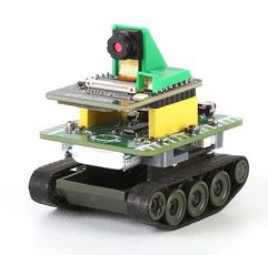
    The camera and control option in one can be possessed with the ESP32 CAM, or if that's not enough, the ESP32-S3-Cam. Control can be transferred to the drive module via I2C. There are also laser distance meters via I2C, and even current and voltage measurement for monitoring battery status.
  • ADVERTISEMENT
  • #21 21478482
    efi222
    Level 19  
    The control of the models from a smartphone is very poor. You don't know what to look at. On the smartphone or the vehicle...
    Only physical buttons or joystick.
  • #22 21478756
    rysin
    Level 12  
    But these bluetooth boards also have one. You can also look at the camera image on the screen. If the ESP32CAM is too weak then you can use the ESP32-S3-CAM. If someone disputed pins not connected in this base board then you can use them interchangeably.
  • #23 21478766
    krzbor
    Level 27  
    efi222 wrote:
    The control of models that a smartphone is very poor
    .
    It depends where you are. If out of the house then the only thing you look at is the smartphone, because you can't see the device anyway.
  • #24 21478780
    efi222
    Level 19  
    Facts. I had forgotten that there is a camera preview :D .
  • #25 21506198
    rysin
    Level 12  
    krzbor wrote:
    At low speeds the engines squeal and the vehicle does not run.
    .
    These drives for these vehicles are too fast. At too low a PWM fill the motor will not start, let alone the whole vehicle. You should start from a certain fill such as 30%, not from zero. With too little fill, the ride is unstable. I have recently been trying to start a vehicle with TT drives with a ratio of 1:120, we'll see what comes out of it.
  • #26 21533015
    rysin
    Level 12  
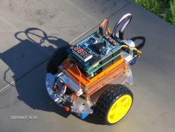
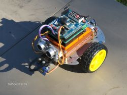
    I also made myself a toy on ESP32 and UNO boards.

    A robot built with ESP32 and UNO boards, mounted on a metal chassis with yellow wheels and an ultrasonic sensor in front. .

    These UNO boards are all wraparound and so the display has to be reprogrammed to display wraparound.

    Small robot built on a wheeled platform with ESP32 and UNO boards, with LED display and visible wires. .

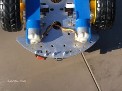
    Don't buy these drives as pictured because these white axles are howling because they are mounted on metal axles in the form of a rod.

    Close-up of a robot chassis with a metal base, black-and-yellow wheels, and two motors with visible white axles.

Topic summary

The discussion revolves around building a remote-controlled tank using a NodeMCU, L298 motor driver, and two motors. The project aims to provide a step-by-step guide for beginners, detailing the connection of the L298 to the motors, operation via PlatformIO/Arduino, and WiFi control. Suggestions include integrating a camera for monitoring, using a virtual touch gamepad for control, and exploring charging station options, such as contactless Qi chargers. Participants discuss motor control issues, proposing solutions like adjusting PWM frequency and implementing closed-loop control for better performance. The conversation also touches on 3D printing components and the use of ESP32 CAM for camera integration.
Summary generated by the language model.
ADVERTISEMENT