Hello
I would like to present and share a universal platform for operating remotely controlled models.
I haven`t posted anything on the forum for many years - it doesn`t mean that nothing was happening, but it wasn`t always worth showing. ;)
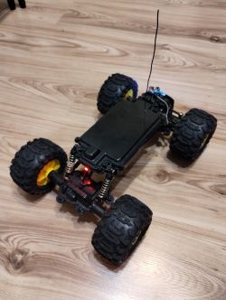
It all started with the fact that I wanted to do something that would give me fun and be an inspiration to "fiddle" with cables and Arduino. So I ordered a tank chassis from a Chinese online store (sinoning.com) and that`s how the adventure began... after the tank, a mini-car appeared (also from the same store), and then, bought for 1/3 of the value of new vehicles, a full-fledged car with 4x4 drive and a remote-controlled fast boat, bought on Allegro as "damaged". The damage to the car consisted of water getting inside and seizing the engine (the car is theoretically waterproof and has positive buoyancy and can also "move" on water), which was revived (by force and then turning by hand), while the boat was theoretically damaged. control, but I didn`t check what happened because from the very beginning I wanted to install my own...
A few words about the control itself:
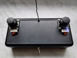
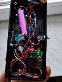
Remote consists of 2 joysticks (Arduino modules), Arduino Nano, Li-Ion battery, BMS system, 5V step-up converter and radio (HC-12 module). No rocket science. I had a huge problem diagnosing the problem that the BMS did not want to charge the battery - the diode was blinking very quickly, as if there was no contact somewhere, or the module was being energized. In desperation, I soldered it directly to the battery (previously through the switch) and this solved the problem. I don`t know why the switch caused such problems - perhaps the contacts provided some electrical resistance and the module was excited, e.g. by the radio or the converter. The remote control has two modes (the mode is changed by long pressing the left joystick): car/boat mode (default - left joystick forward/back, right joystick right/left) and tank mode (both front/rear joysticks for differential control). Holding the left joystick for a shorter time changes the lamp mode (bright/medium/off) in the big car.
Receivers they also consist of Arduino Nano, HC-12, as well as (cars, tank) BMS and an H-bridge for controlling the engines (in a boat, the engine is operated by a servo). The smallest car is powered by one LI-ION cell and a STEP-UP converter, hence the large capacitor so that voltage drops do not reset the Arduino. The remaining models run on two 18650s (the large car also has a capacitor on the power supply, but it is not needed).
Additional information
The large car has lights based on WS2812B (two white at the front, one red at the rear).
Boat steeringis more complicated because the "ordinary PWM code" cannot be used to operate the servo, as it is done in a different way. All receivers have an identical code; At startup, Arduino checks whether there is appropriate voltage on one of the pins (supplied from the 3.3V output) and if so, it activates the "boat mode". Other models do not have this pin bridged - this way the program is universal and there is no need to add another "mode" in the remote control.
The boat has protection against low battery voltage - it is measured by a voltage divider and has two activation thresholds. When the first one is reached, an acoustic signal is emitted for a few seconds (5V buzzer controlled by the BS170 transistor). When the second one is reached, the acoustic signal turns on permanently and the engine power is reduced (PWM max 50%). The BMS used in the factory cells does not cut off the power supply even in the event of deep discharge, which makes sense because it is better to kill the batteries than to get the boat stuck 10 meters from the shore...
The servo is controlled using a software library. This is because the default servo library had a conflict with the library responsible for controlling the WS2812 (probably a conflict due to the use of the same timer).
The program also has commented sections related to testing the battery in the boat - before I discovered that the BMS did not cut it off, I wrote a script that saved the lowest measured supply voltage in EEPROM and after connecting the Arduino to the computer, sent it via Serial. I wanted to know to what level the cells could be discharged to properly set the protection thresholds, but it turned out to be unnecessary.
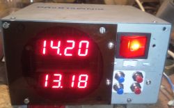
The remote control and the large toy car have connectors for charging the batteries; there are chargers for a small car and a boat.
Generally, I discovered that the "spiral" antenna in the transmitter works poorly, but a regular wire of appropriate length works well. The antennas in the remote control and cars are mounted in goldpin sockets so that they can be easily removed for transport. The boat has a default spiral antenna. HC-12 radios are very cool, the theoretical range (at low bitrate, direct visibility) is up to one kilometer. I am attaching two documents that will be useful for their operation - they contain a description of the functions and configuration.
Calibration is needed to adapt the code to a given joystick (neutral point) and servo (also). The values are described in the comments.
I don`t have any diagrams, but I think you can easily figure out what and how based on the descriptions and photos. I know that (especially in the remote control) there is a spider`s web of cables, but I don`t waste my time designing boards, I enjoy electronics and writing programs.
The code is heavily commented (in English), so understanding the programs should not be a problem. The range in the selected configuration (radio bitrate, antenna) is at least 200m (maybe more, I haven`t checked, at such a distance it is difficult to control the model).
If anyone is interested, it is worth following this topic, if there is an update of the program(s), I will add it.
Below are the photos and code.
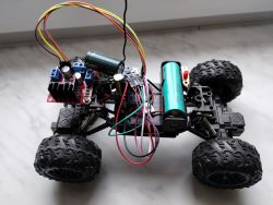
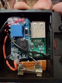

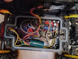
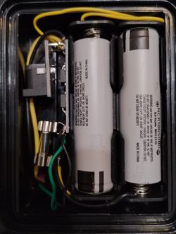
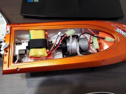
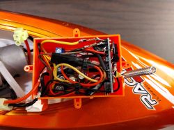
TRANSMITTER
// delay(1);//It is necessary for proper message sending. Without this messages sometimes are merged.
//$$ separates values, ! ends the message


#include <SoftwareSerial.h>
SoftwareSerial mySerial(2, 3); //RX, TX

//L: 3-507-1017 --> 1020 for smooth operation [506;508]
//R: 3-526-1017 --> 1020 for smooth operation [525;527]
//STEER [R]: 0-517-1022 [521;523]
int ax; //analog read joystick A
byte af; //analog joystick A forward
byte ab; //analog joystick A backward

int bx; //analog read joystick B
byte bf; //analog joystick B forward
byte bb; //analog joystick B backward

boolean mode = false; //Tank or Car mode (default: car)
int buttontest; //conunting time of button being pressed

String toSend;


void setup()
{
  pinMode(4, OUTPUT);
  pinMode(12, OUTPUT);
  pinMode(11, OUTPUT);
  pinMode(10, OUTPUT);
  pinMode(9, OUTPUT);
  pinMode(5, OUTPUT);
  pinMode(6, OUTPUT);

  digitalWrite(4, HIGH); //DISABLE AT MODE
  digitalWrite(12, HIGH);//RIGHT JOYSTICK VCC
  digitalWrite(11, LOW);//RIGHT JOYSTICK GND
  digitalWrite(10, HIGH);//LEFT JOYSTICK VCC
  digitalWrite(9, LOW);//LEFT JOYSTICK GND
  digitalWrite(5, LOW);//BUZZER GND
  digitalWrite(6, LOW);//BUZZER VCC

  pinMode(A0, INPUT); //LEFT JOYSTICK BUTTON
  pinMode(A1, INPUT); //RIGHT JOYSTICK BUTTON
  pinMode(A5, INPUT); //RIGHT JOYSTICK FORWARD & BACKWARD
  pinMode(A6, INPUT); //RIGHT JOYSTICK RIGHT & LEFT
  pinMode(A2, INPUT); //LEFT JOYSTICK FORWARD & BACKWARD

  Serial.begin(9600);
  pinMode(4, OUTPUT); //for MODE setup
  digitalWrite(4, LOW); //ENTER AT MODE
  delay(50);//necessary to wait after mode change
  mySerial.begin(9600);//9600 adjust after adjusting communication speed using AT+BXXX
  mySerial.println("AT+FU3");
  delay(50);
  mySerial.println("AT+B9600");//9600
  delay(50);
  mySerial.println("AT+RX"); //AT MODE REQUIRED TO BE ON (4 LOW)
  delay(100);
  digitalWrite(4, HIGH); //EXIT AT MODE
  delay(50);//necessary to wait after mode change
}


void loop()
{
  //RESET OLD VALUES TO AVOID CONFLICTS
  af = 0;
  ab = 0;
  bf = 0;
  bb = 0;


  ////////////////////////////////STEERING MODE CHECK
  if (analogRead(A0) < 10) //BUTTON PRESSED

  {
    buttontest = buttontest + 1; //COUNTING TIME OF BUTTON BEING PRESSED
    mySerial.print("BUTTON PRESSED !");
    Serial.println("BUTTON PRESSED !");
  }
  else
  {
    buttontest = 0; //RESET IN CASE OF ACCIDENTAL CLICK
  }

  //Serial.println(buttontest);

  if (buttontest == 40 ) //BUTTON PRESSED - SENT LIGHT ADJUST SIGNAL
  {
    toSend = String("E") + "!";
    mySerial.print(toSend);
    delay(1);
    digitalWrite(6, HIGH);
    delay(100);
    digitalWrite(6, LOW);
    delay(100);
    digitalWrite(6, HIGH);
    delay(100);
    digitalWrite(6, LOW);
    delay(1000);
  }


  if (buttontest == 41) //BUTTON PRESSED - SENT LIGHT ON/OFF SIGNAL
  {
    toSend = toSend = String("F") + "!";
    mySerial.print(toSend);
    delay(1);
    digitalWrite(6, HIGH);
    delay(1000);
    digitalWrite(6, LOW);
  }


  if (buttontest >= 42) //BUTTON PRESSED - CHANGE TO TANK MODE
  {
    mode = !mode;
    buttontest = 0;
    mySerial.print("MODE CHANGED !");
    delay(1);
    Serial.println("MODE CHANGED !");
    digitalWrite(6, HIGH);
    delay(4000);
    digitalWrite(6, LOW);
  }


  ////////////////////////////////////////LEFT JOYSTICK READ & CALCULATE
  ax = analogRead(A2); //LEFT JOYSTICK
  //  if (mode == 1)
  //  {
  //    Serial.print("A2 LEFT:  ");
  //    Serial.println(ax);
  //  }
  //  else
  //  {
  //    Serial.print("A2 MOVE: ");
  //    Serial.println(ax);
  //  }


//Serial.print("AX READ: ");
//Serial.println(ax);

  //af is PWM for A engine forward
  if (ax > 508)
  {
    af = map(ax, 508, 1020, 0, 255); //af is PWM for A engine forward
    //Serial.print("LEFT FORWARD: ");
    //Serial.println(af);
    toSend = "A" + String(af, DEC) + "!";
    mySerial.print(toSend);
    delay(5);
  }

if (ax >= 506 && ax <=508) //to send zero command in case of neutral joistick position
{
     toSend = "A" + String(0, DEC) + "!";
     mySerial.print(toSend);
     delay(5);
     toSend = "B" + String(0, DEC) + "!";
     mySerial.print(toSend);
     delay(5);
}

  if (ax < 506)
  {
    ab = map(ax, 3, 506, 255, 0); //ab is PWM for A engine backward
    //Serial.print("LEFT BACKWARD: ");
    //Serial.println(ab);
    toSend = "B" + String(ab, DEC) + "!";
    mySerial.print(toSend);
    delay(5);
  }
  ////////////////////////////////END OF LEFT JOYSTICK READ & CALCULATE


  ////////////////////////////////////////RIGHT JOYSTICK READ & CALCULATE
  ///////////READING POSITION FROM CORRECT JOYSTICK OUTPUT
  if (mode == 1)
  {
    bx = analogRead(A5); //IF IN TANK MODE
    //    Serial.print("A5 RIGHT: ");
    //   Serial.println(bx);
  }
  else
  {
    bx = analogRead(A4); //IF IN CAR MODE
    //Serial.print("A6 STEER: ");
    //Serial.println(bx);
  }
  ///////////END OF READING FROM CORRECT JOYSTICK OUTPUT

  ///////////CALCULATING PWM ACCORDING TO
  //JOYSTICK'S ZERO CALIBRATION POSITION
  if (mode == 1) //IF IN TANK MODE
  {
    if (bx > 527)
    {
      bf = map(bx, 527, 1020, 0, 255); // bf is PWM for B engine forward
      //Serial.print("RIGHT FORWARD: ");
      //Serial.println(bf);
      toSend = "C" + String(bf, DEC) + "!";
      mySerial.print(toSend);
      delay(5);
    }

    if (bx < 525)
    {
      bb = map(bx, 3, 527, 255, 0); //bb is PWM for B engine backward
      //Serial.print("RIGHT BACKWARD: ");
      //Serial.println(bb);
      toSend = "D" + String(bb, DEC) + "!";
      mySerial.print(toSend);
      delay(5);
    }
  }
  else //IF IN CAR MODE
  {
    if (bx > 517)
    {
      bf = map(bx, 517, 1022, 0, 255); //bf is PWM for B engine forward
      //Serial.print("STEER RIGHT: ");
      //Serial.println(bf);
      toSend = "C" + String(bf, DEC) + "!";
      mySerial.print(toSend);
      //Serial.println(toSend);
      delay(5);
    }

if (bx >= 516 && bx <=517) //to send zero command in case of neutral joistick position
{
     toSend = "C" + String(0, DEC) + "!";
     mySerial.print(toSend);
     delay(5);
     toSend = "D" + String(0, DEC) + "!";
     mySerial.print(toSend);
     delay(5);
}

    if (bx < 516)
    {
      bb = map(bx, 0, 517, 255, 0); //bb is PWM for B engine backward
      //Serial.print("STEER LEFT: ");
      //Serial.println(bb);
      toSend = "D" + String(bb, DEC) + "!";
      mySerial.print(toSend);
      //Serial.println(toSend);
      delay(5);
    }
  }

  ////////////////RIGHT JOYSTICK DIAG
  //Serial.print("AX: ");
  //Serial.println(ax);
  //Serial.print("BX: ");
  //Serial.println(bx);
  /////////////////////////////////END OF LEFT JOYSTICK READ & CALCULATE


}// END OF LOOP
RECEIVER
#include <SoftwareSerial.h>
#include <Adafruit_NeoPixel.h>
//#include <EEPROM.h>
#include <PWMServo.h>//software PWM used because servo library had conflict with other used functions using PWM generated by the same internal closk
PWMServo myservo;  // create servo object to control a servo
SoftwareSerial mySerial(2, 3); //RX, TX
Adafruit_NeoPixel
strip = Adafruit_NeoPixel(3, 13, NEO_GRB + NEO_KHZ800); //NO of pixels, PIN
byte af, ab, bf, bb;
boolean light = 0; //LIGHT ON/OFF, default = OFF
boolean change = false; // flag to mark change to use WS2812B communication once for light ON/OFF. Constant communication interrupts message receiving
boolean lightadjustment = false; // flag to mark change to use WS2812B communication once for light level adjustment. Constant communication interrupts message receiving
byte xy; //light brightness pre set setting
byte brightness = 64; //brightness level (0-255), default = 64
boolean boatmode;// if true, then boat mode
byte modecount = 0; //no. of successful read sequences
int  bootval;// voltage check at boot to detect whether it is a boat or not
byte neutral = 85; //neutral position of servo
byte servoangle; //servo's angle
int serwoPWM;// calculated value to steer servo by generating PWM
unsigned long counter; //time from last message
unsigned long nowtime; //time now. Used further to calculate time past since previous loop
//unsigned long pinginterval; // for signalling range ping messages
float voltageread; //voltage read at input
float batvoltage; //calculated battery level (incl. calculated offset)
byte mediumdischargecount = 0; //to avoid one - time battery voltage drops,alarm will be activated after few times threshold is reached
byte deepdischargecount = 0; //to avoid one - time battery voltage drops,alarm will be activated after few times threshold is reached
long mediumbatlevelalarmtime; //time of buzzer's activation
boolean mediumbatlevelalarmactivation = false;
boolean deepdischargealarmactivation = false;

//int lowestbatvoltage; ////////////////////USED ONLY AT BOOT TO HAVE ANY VALUE FOR IF FUNCTION TO COMPARE TO
//int lowestbatEEPROM;


void setup()
{
  //writeIntIntoEEPROM(7000);//EEPROM LOW RESET USED TO START A NEW RECORDING
  //PIN D11 BURNT !!!!!!!!!!!!
  //PINS A6&A7 cannot be used as analog output in Arduino Nano
  pinMode(4, OUTPUT); //AT MODE SWITCH
  pinMode(5, OUTPUT);
  pinMode(6, OUTPUT);
  pinMode(10, OUTPUT);//SERVO
  pinMode(13, OUTPUT); //built in led + WS2812B
  pinMode(A1, OUTPUT); //GND for voltage sensing
  pinMode(A0, INPUT); //voltage check at boot to detect whether it is a boat or not
  pinMode(A2, INPUT); //battery voltage check
  pinMode(A5, OUTPUT); //low battery buzzer output
  digitalWrite(A1, LOW); //GND for voltage sensing
  digitalWrite(A5, LOW); //deactivate buzzer
  digitalWrite(4, LOW); //ENTER AT MODE
  delay(50);//necessary to wait after AT mode change

  Serial.begin(9600);
  mySerial.begin(9600);//adjust after adjusting communication speed using AT+BXXX
  mySerial.println("AT+FU3");
  delay(50);
  mySerial.println("AT+B9600");
  delay(50);
  mySerial.println("AT+RX"); //AT MODE REQUIRED TO BE ON (4 LOW)
  delay(100);
  digitalWrite(4, HIGH); //EXIT AT MODE
  delay(50);//necessary to wait after mode change\
  analogReference(INTERNAL); //1,1V
  modecheck(); //Function to detect whether hardware is a boat or not

  analogReference(INTERNAL); //1,1V for battery measurement

  if (boatmode == true)
  {
    myservo.attach(SERVO_PIN_B); //Library works only at PIN9 and 10 (already used)
    servostart(); //Sequence for servo movement at boat's boot
    testbeep(); //Test buzzer
    //Serial.print("LOWEST VOLTAGE FROM EEPROM: ");
    //Serial.println(readIntFromEEPROM());
  }
  else
  {
    strip.begin(); // INITIALIZE NeoPixel strip object
    strip.clear();
    strip.show();
    startsequence(); //LED BLINK at car's boot
  }
} ///////////////////////////////////////////END OF SETUP


void loop()
{
  ///////////////////////LOST CONNECTION PROTECTION
  nowtime = millis();
  if ((nowtime - counter) > 1000) //1000 MS SIGNAL LOST TRIGGER
  {
    //Serial.println(nowtime-counter);
    //Serial.println("CONNECTION LOST !!!");
    if (boatmode == false) //IF IN CAR MODE
    {
      digitalWrite(11, LOW);
      digitalWrite(10, LOW);
      digitalWrite(6, LOW);
      digitalWrite(5, LOW);
    }
    else //IF IN BOAT MODE
    {
      digitalWrite(6, LOW);
      digitalWrite(5, LOW);
    }
  }
  ///////////////////////END OF LOST CONNECTION PROTECTION

  //////////////////////////100 MS SIGNAL PING TRIGGER
  //    if ((nowtime - pinginterval) > 50)
  //    {
  //      //Serial.println("PING INTERVAL");
  //      //Serial.println(nowtime-pinginterval);//Loop time
  //      pinginterval = millis();
  //      ();
  //    }
  ///////////////////////END OF SIGNAL PING TRIGGER


  ////////////////////////////////////// MESSAGE RECEIVING
  while (mySerial.available())
  {
    static String receivedMessage = ""; // Store the received message
    char receivedChar = mySerial.read();

    if (receivedMessage.length() == 0)
    {
      if (receivedChar == 'A' || receivedChar == 'B' || receivedChar == 'C' || receivedChar == 'D')
      {
        receivedMessage = receivedChar; // Start building the message with the received character
      }
      if (receivedChar == 'F')
      {
        light = !light;
        change = true; // FLAG FOR LIGHT STATE CHANGE
        //Serial.println("LIGHT ON/OFF !");
      }
      if (receivedChar == 'E')
      {
        lightadjustment = true; // FLAG FOR LIGHT ADJUSTMENT
      }
    }//////////////END OF receivedMessage.length() == 0

    else
    {
      if (receivedChar == '!')
      {
        // Message received and ends with '!'
        Serial.println(receivedMessage);//////////////////////////////////////
        // Serial.println("MESSAGE RECEIVED, CONNECTION OK!");
        counter = millis();
        processMessage(receivedMessage, boatmode, neutral, deepdischargealarmactivation);
        receivedMessage = ""; // Clear the received message for the next one
      }
      else
      {
        receivedMessage += receivedChar;
      }
    }
  }//END OF WHILE
  /////////////////////////////////// END OF MESSAGE RECEIVING

  ////////////////////////////////// LIGHT ON&OFF
  if (light == true && change == true) //turn ON the light to the pre set level
  {
    change = false; //function activated only once
    lighton(); // turn ON the light function
  }

  if (light == false && change == true) //turn OFF the light
  {
    change = false; //function activated only once
    lightoff(); // turn the light OFF function
  }
  ////////////////////////////////// END OF LIGHT ON&OFF


  ////////////////////////////////// LIGHT LEVEL & ADJUST
  if (lightadjustment == true)
  {
    if (xy == 0)
    {
      Serial.println("MAX");
      strip.setBrightness(255);
      strip.show();
      xy = 1;
      lightadjustment = false;
    }
  }

  if (lightadjustment == true)
  {
    if (xy == 1)
    {
      Serial.println("DEFAULT");
      strip.setBrightness(64);
      strip.show();
      xy = 0;
      lightadjustment = false;
    }
  }
  ////////////////////////////////// END OF LIGHT LEVEL &ADJUST


  /////////////////////////////////// VOLTAGE READ AND BUZZER ACTIVATION
  if (boatmode == true)
  {
    voltageread = analogRead(A2);
    //Serial.println(voltageread);
    batvoltage = 10.88 * (long)voltageread * 1100 / 1024; //Convert voltageread to long to correctly handle multiplication (without int overflow). Voltage appplied through 1/10 divider. 0.88 after 10 for calibration
    //Serial.print("READ BATTERY VOLTAGE: ");
    //Serial.println(batvoltage);
  }

  //batvoltage=1.3;// BUZZER & LOW BATTERY PWM TEST


  if (batvoltage <= 6.6)
  {
    if (mediumbatlevelalarmactivation == false) //if medium battery level alarm has not been activated yet
    {
      mediumdischargecount = mediumdischargecount + 1;
      //Serial.print("MEDIUM BAT VOLTAGE COUNT:");
      //Serial.println(mediumdischargecount);
    }
  }

  if (batvoltage <= 5.8)
  {
    if (deepdischargealarmactivation == false) ////if battery deep discharge alarm has not been activated yet
    {
      deepdischargecount = deepdischargecount + 1;
      //Serial.print("DEEP BAT VOLTAGE COUNT:");
      //Serial.println(deepdischargecount);
    }
  }

  if (mediumdischargecount == 10) //medium battery level alarm activation
  {
    if (mediumbatlevelalarmactivation == false) //activate medium battery alarm only once
    {
      mediumbatlevelalarmtime = millis();
      Serial.println("MEDIUM BATTERY LEVEL ALARM !!!");
      digitalWrite(A5, HIGH); //activate buzzer
      mediumbatlevelalarmactivation = true; //medium battery alarm will not be activated again
    }
  }

  if (((millis() - mediumbatlevelalarmtime) > 10000 && (millis() - mediumbatlevelalarmtime) < 14000) ) //if alarm has been activated for more than 10 seconds but only once
  {
    digitalWrite(A5, LOW); //turn off the buzzer
  }

  if (deepdischargecount == 10) //low battery level alarm activation
  {
    digitalWrite(A5, HIGH); //activate buzzer
    if (deepdischargealarmactivation == false)
    {
      Serial.println("LOW BATTERY LEVEL ALARM !!!"); //send message only once
    }
    deepdischargealarmactivation = true;
    digitalWrite(A5, HIGH); //permanently activate the buzzer
  }

  /////////////////////////////////// END OF VOLTAGE READ AND BUZZER ACTIVATION

  //  /////////////////////////////////// VOLTAGE READ AND EEPROM READ&WRITE
  //  if (boatmode == true)
  //  {
  //    voltageread = analogRead(A2);
  //    Serial.print("ANALOG VOLTAGE: ");
  //    Serial.println(voltageread);
  //    batvoltage = 10.88 * (long)voltageread * 1100 / 1024; //Convert voltageread to long to correctly handle multiplication (without int overflow). Voltage appplied through 1/10 divider. 0.88 after 10 for calibration
  //    Serial.print("READ   VOLTAGE: ");
  //    Serial.println(batvoltage);
  //
  //    if (batvoltage > 3000) //to prevent from reading when battery is not connected (analog pin is grounded by 1k resistor)
  //    {
  //      if (batvoltage < lowestbatEEPROM) //if current voltage is lower than the lowest recorded in EEPROM
  //      {
  //        lowestbatvoltage = batvoltage;
  //        writeIntIntoEEPROM(lowestbatvoltage);
  //        Serial.print("!!!!!! NEW LOWEST VOLTAGE RECORDED: ");
  //        Serial.println(lowestbatvoltage);
  //      }
  //    }
  //
  //    Serial.print("LOWEST VOLTAGE: ");
  //    Serial.print(lowestbatvoltage);
  //    Serial.println(" (SINCE BOOT)");
  //    lowestbatEEPROM = readIntFromEEPROM(); //read lowest battery value stored in EEPROM
  //    Serial.print("LO BAT EEPROM : ");
  //    Serial.println(lowestbatEEPROM);
  //  }/////////////////////////////////// END OF VOLTAGE READ AND EEPROM READ&WRITE


}////////////////////////////////////END OF LOOP


////////////////////////////////////FUNCTIONS///////////////////////////////////////////

///////////////////////////////////////////PROCESS MESSAGE
void processMessage(String receivedMessage, boolean boatmode, byte bootval, boolean deepdischargealarmactivation)
{
  //Serial.println(receivedMessage); //////////////////////////////// RECEIVED MESSAGE

  if (receivedMessage.charAt(0) == 'A')
  {
    af = receivedMessage.substring(1).toInt();
  }

  if (receivedMessage.charAt(0) == 'B')
  {
    ab = receivedMessage.substring(1).toInt();
  }

  if (receivedMessage.charAt(0) == 'C')
  {
    bf = receivedMessage.substring(1).toInt();
  }

  if (receivedMessage.charAt(0) == 'D')
  {
    bb = receivedMessage.substring(1).toInt();
  }


  if (boatmode == false) //////////////////////PWM GENERATION IF IN CAR MODE
  {
    if (af > 3) //A FORWARD PWM&LOW
    {
      analogWrite(11, af);
      digitalWrite(10, LOW);
    }

    if (ab > 3) //A BACKWARD PWM&LOW
    {
      digitalWrite(11, LOW);
      analogWrite(10, ab);
    }

    if (bf > 3) //B FORWARD PWM&LOW
    {
      analogWrite(6, bf);
      digitalWrite(5, LOW);
    }

    if (bb > 3) //B BACKWARD ENGINE PWM&LOW
    {
      digitalWrite(6, LOW);
      analogWrite(5, bb);
    }

    if (bf <= 3 && bb <= 3) //FOR ZEROING AS PROGRAM DO NOT ZERO BY DEFAULT(DO NOT INTERPRETE "0" VALUE)
    {
      digitalWrite(6, LOW);
      digitalWrite(5, LOW);
    }

    if (af <= 3 && ab <= 3) //FOR ZEROING AS PROGRAM DO NOT ZERO BY DEFAULT (DO NOT INTERPRETE "0" VALUE)
    {
      digitalWrite(10, LOW);
      digitalWrite(11, LOW);
    }
  } ////////////////////////END OF CAR MODE PWM GENERATION

  else//////////////////////PWM GENERATION IF IN BOAT MODE
  {
    if (af > 3) //A FORWARD PWM&LOW
    {
      if (deepdischargealarmactivation == false) //if deep battery discharege alarm is not activated
      {
        analogWrite(5, af);
        digitalWrite(6, LOW);
      }
      else //if deep battery discharege alarm is activated
      {
        analogWrite(5, (af / 3)); //speed reduced by 33%
        digitalWrite(6, LOW);
      }
    }

    if (ab > 3) //A BACKWARD PWM&LOW
    {
      if (deepdischargealarmactivation == false) //if deep battery discharege alarm is not activated
      {
        digitalWrite(5, LOW);
        analogWrite(6, ab);
      }
      else //if deep battery discharege alarm is activated
      {
        digitalWrite(5, LOW);
        analogWrite(6, (ab / 3)); //speed reduced by 33%
      }
    }

    if (bf > 3) //B FORWARD PWM&LOW
    {
      servoangle = map(bf, 3, 255, neutral, (neutral - 55));
      myservo.write(servoangle);
    }

    if (bb > 3) //B BACKWARD ENGINE PWM&LOW
    {
      servoangle = map(bb, 3, 255, neutral, (neutral + 55));
      myservo.write(servoangle);
    }


    if (af <= 3 && ab <= 3) //FOR ZEROING AS PROGRAM DO NOT ZERO BY DEFAULT (DO NOT INTERPRETE "0" VALUE)
    {
      digitalWrite(5, LOW);
      digitalWrite(6, LOW);
    }

    if (bf <= 3 && bb <= 3) //FOR NEUTRAL POSITIONAS PROGRAM DO NOT ZERO BY DEFAULT(DO NOT INTERPRETE "0" VALUE)
    {
      myservo.write(neutral);
    }
  } ////////////////////////END OF BOAT MODE PWM GENERATION

  //    FOR DEBUG ONLY. USING INTERRUPTS RECEIVED SIGNAL & OPERATION
  //    Serial.print("AF: ");
  //    Serial.println(af);
  //    Serial.print("AB: ");
  //    Serial.println(ab);
  //    Serial.print("BF: ");
  //    Serial.println(bf);
  //    Serial.print("BB: ");
  //    Serial.println(bb);
  //    FOR DEBUG ONLY. USING INTERRUPTS RECEIVED SIGNAL & OPERATION
} /////////////////////////////////////////////////Process Message End

void lighton()
{
  strip.setBrightness(brightness);
  strip.setPixelColor(0, strip.Color(255, 255, 255));
  strip.setPixelColor(1, strip.Color(255, 255, 255));
  strip.setPixelColor(2, strip.Color(255, 0, 0));
  strip.show();
}

void lightoff()
{
  strip.setBrightness(0);
  strip.show();
}

void startsequence() //LED BLINK AT START
{
  digitalWrite(13, HIGH); //BUILT IN LED ON
  strip.setPixelColor(0, strip.Color(255, 255, 255));
  strip.setPixelColor(1, strip.Color(255, 255, 255));
  strip.setPixelColor(2, strip.Color(255, 0, 0));
  strip.show();
  delay(50);
  digitalWrite(13, LOW); //BUILT IN LED OFF
  strip.setBrightness(0);
  strip.show();
  delay(50);
  digitalWrite(13, HIGH); //BUILT IN LED ON
  strip.setBrightness(255);
  strip.setPixelColor(0, strip.Color(255, 255, 255));
  strip.setPixelColor(1, strip.Color(255, 255, 255));
  strip.setPixelColor(2, strip.Color(255, 0, 0));
  strip.show();
  delay(50);
  digitalWrite(13, LOW); //BUILT IN LED OFF
  strip.setBrightness(0);
  strip.show();
}

void servostart() //SEQUENCE OF SERVO MOVEMENTS AT START
{
  myservo.write(neutral + 55);                // sets the servo position according to the scaled value
  delay(200);
  myservo.write(neutral - 55);                // sets the servo position according to the scaled value
  delay(200);
  myservo.write(neutral); // sets the servo position according to the scaled value
  delay(100);
}

void testbeep()
{
    digitalWrite(A5, HIGH);
    delay(50);
    digitalWrite(A5, LOW);
    delay(50);
    digitalWrite(A5, HIGH);
    delay(50);
    digitalWrite(A5, LOW);
    delay(50);
    digitalWrite(A5, HIGH);
    delay(50);
    digitalWrite(A5, LOW);
}

boolean modecheck() //voltage check at boot to detect whether it is a boat or not
{
  for (byte i = 0; i < 5; i++)
  {
    bootval = analogRead(A0);
    if (bootval > 600 && bootval < 700) //A0 value at USB approx. 659. 655, 665, at boat different
    {
      modecount = modecount + 1;
    }
    delay(100);
  }

  if (modecount == 5)
  {
    boatmode = true;
    Serial.println("BOAT MODE !");
    return boatmode;
  }
  else
  {
    Serial.println("CAR MODE !");
  }
}// END OF MODE CHECK

//void writeIntIntoEEPROM(int lowestbatvoltage)
//{
//  EEPROM.update(0, lowestbatvoltage >> 8); //address, variable. Shift by 8n bite, meaning saving only firts 8 bits from the digit in the first (out of two) bytes
//  EEPROM.update(0 + 1, lowestbatvoltage & 0xFF); //For the second byte, we make an AND operation with 0xFF, which is the hexadecimal representation of 255 (you could write “& 255” instead of “& 0xFF”). This way, we only get the 8 bits on the right.
//}
//
//int readIntFromEEPROM()
//{
//  return lowestbatEEPROM = (EEPROM.read(0) << 8) + EEPROM.read(0 + 1);
//}

//void sendping()
//{
//  mySerial.print("XXXXX");
//  Serial.println("!"); //////////////////////////////// PING SENT
//}Cool? Ranking DIY


