logo elektroda
logo elektroda
X
logo elektroda

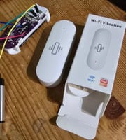
Converting Tuya Vibration Sensor with BK7231N MCU to OpenBeken Integration

DL5SMB 372 5
ADVERTISEMENT
  • #1 21484540
    DL5SMB
    Level 2  
    Hello everyone,

    Has anyone ever converted a Tuya Vibration Sensor to Openbeken?

    I have flashed the device but now I am pretty clueless on how to proceed as I have not found a similar device in the tutorials.
    I am not even sure there is a driver yet.

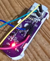
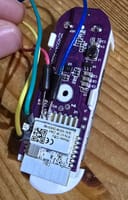
    The MCU is a CBU /BK7231N and the acceleration sensor seems to be a LIS2DW12. There is at least a development board with this sensor and it seems pretty identical.

    It seems the communication works via I2C and then there is an interrupt to give out the signal.

    PIN8 (P8) is the button, PIN19 (P9) the LED.

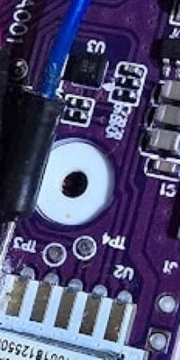
    Pinning out the sensor is difficult but TP4 is Pin10(P6), TP3 is Pin11 (P26) and i am measuring 10K from TP1 to PIN18 (CEN)

    Maybe someone has already done a similar device or it is not as hard as I assume to make it work.

    Any help is appreciated.

    Sascha
  • ADVERTISEMENT
  • #2 21485698
    divadiow
    Level 34  
    I don't recognise this type of device as having been posted about before. I guess if it's an i2c sensor then it would need a driver writing for it.

    Info from your backup

    Code: JSON
    Log in, to see the code


    Code: Text
    Log in, to see the code


    Boot (without sensor of course, hence i2c errors)
    Code: Text
    Log in, to see the code


    Added after 1 [minutes]:

    are you running OpenBeken on it now and have you received an i2c address back from scani2c soft? https://github.com/openshwprojects/OpenBK7231T_App/blob/main/docs/commands-extended.md
  • ADVERTISEMENT
  • #3 21485947
    DL5SMB
    Level 2  
    Wooow, thanks a lot Divadiow!!

    This is a lot of helpful information, especially the boot sequence. I tried reading out the I2C, but it seems I have not found the right pinout.

    I have noticed some of my multimetered results have been wrong - nevertheless.

    The boot sequence suggests:

    PIN16=Reset button (tested - correct)
    PIN9=Status LED (tested - correct)
    PIN26= Basic pin / Gate PIN (????)
    PIN20=Battery ADC?
    PIN17=Wifi LED (I don't think there is a second LED on the board)
    PIN6= Tamper Pin (I guess the output of the I2C Sensor)

    I tried Pin6 (that's obviously wrong) and 26 for SDA and SCL with soft I2c,
    reversed it and later did the same with P8 and P7.

    Also I noticed sometimes I do see the scan running from 1 to 128, and sometimes I just get the the "Result OK" message.
    Strange.
  • ADVERTISEMENT
  • #4 21486052
    divadiow
    Level 34  
    DL5SMB wrote:
    PIN20=Battery ADC?

    I assumed that was ADC too.

    Not sure what the meaning is of the apparent doubling-up of LED assignment. I recognise basic_pin_pin but don't recall what it meant in the context of OBK. Will try to find.

    If the attached is the correct datasheet, and looking at one of the pics, could it be that SDA/SCL is P8/P7 via two resistors? Bit of a guess, can't really see enough.

    Close-up of a circuit board with a purple base and electronic components.
  • ADVERTISEMENT
  • #6 21487374
    DL5SMB
    Level 2  
    Okay, now I got I2C - and am probably stuck missing a driver :-D

    The address is 0x26.

    Is it possible that it won't start / connect to WiFi anymore after putting in P20 BAT ADC 1?

    Really strange. I experienced something like this earlier when I put it into deepsleep and could not wake it anymore. Ended with reflashing .
ADVERTISEMENT