logo elektroda
logo elektroda
X
logo elektroda

Door Sensor D06 (BK7231N/CB3S) with TuyaMCU (DeepSleep)

CMY 6120 49
ADVERTISEMENT
  • One more Door Sensor
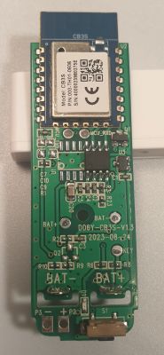
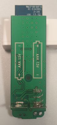
    PCB with CB3S module and component markings View of door sensor board with slots for AAA batteries.

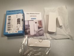
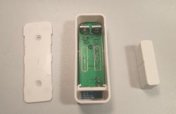
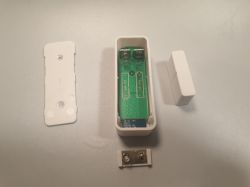
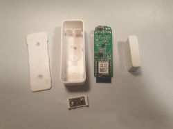
    Door and window sensor set with manual and packaging. Photo of an open door sensor casing showing the circuit board. Disassembled DS06 door sensor with visible interior. Disassembled door sensor showing circuit board and casing.

    First Look
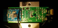
    WiFi Chipset BK7231N/CB3S connected only to TuyaMCU via serial interface. Even LED connected to TuyaMCU.
    TuyaMCU has power control for WiFi module.

    There are two pins on the bottom of the board P3 and P2. Seems like this is for external sensor like a water leak sensor. To use it need Q2, R10, R9. But it use the same TuyaMCU pin that used for Magnetic Field Sensor now. So U3 needs to be dismounted in this case. (??? maybe they have a HighZ output and can work at the same time)


    Firmware update
    Firmware update possible only by desoldering chipset because TX-RX already connected to TuyaMCU .

    Or maybe OTA? :)
    OTA is probably possible via tuya-cloudcutter project https://github.com/tuya-cloudcutter/tuya-cloudcutter/tree/main
    I found 2 similar sensors there:
    - https://github.com/tuya-cloudcutter/tuya-clou...es/tuya-generic-cb3s-door-sensor-v1.0.10.json
    - https://github.com/tuya-cloudcutter/tuya-clou...b/master/devices/avatto-ds06-door-sensor.json
    Last one looks better.

    Unfortunately, my unit has a new firmware version, so tuya-cloudcutter doen't work for it. No OTA update for today.
    I conected it via serial inteface, and download original firmware. (You don't need to desolder WiFi chip, easy way to take of TuyaMCU. I has only 8 pins)

    tuya-cloudcutter/profile-building/build_profile.py gaves me this:
    [+] Processing file='Tuya-Generic_DoorSensor-D06.bin' as Tuya-Generic_DoorSensor-D06
    RBL containers:
            0x10f9a: bootloader - [encoding_algorithm=NONE, size=0xea20]
                    extracted to Tuya-Generic_DoorSensor-D06
            0x129f0a: app - [encoding_algorithm=NONE, size=0xe0820]
                    extracted to Tuya-Generic_DoorSensor-D06
    Storage partition:
            0x1ee000: 60 KiB - 7 keys
            - 'gw_bi'
            - 'gw_di'
            - 'wf_start_md'
            - 'gw_wsm'
            - 'gw_ai'
            - 'record_head'
            - 'baud_cfg'
                    extracted all keys to Tuya-Generic_DoorSensor-D06/Tuya-Generic_DoorSensor-D06_storage.json
    App code `user_param_key`:
            - not found!
    [+] Searching for known exploit patterns
    [+] Matched pattern for BK7231N version SDK 2.3.1, payload type ssid
    [!] The binary supplied appears to be patched and no longer vulnerable to the tuya-cloudcutter exploit.


    OpenBK firmware was uploded via serial inteface and working good.

    Draft config
    Code: JSON
    Log in, to see the code


    Pins:
    RX1 and TX1 connected to TuyaMCU.

    TuyaMCU channels
    #1 - Door Sensor (0-Closed, 1-Open)
    #3 - Battery ( 2 -> 3V, 1-> ???, 0->??? )

    Everything exactly like here Energy-saving (?) Battery-operated door / window sensor for WiFi DS06

    Just a log of TuyaMCU communication:
    Info:CMD:[WebApp Cmd 'uartSendHex 55 AA 00 01 00 00 00' Result] OK
    Info:TuyaMCU:TUYAMCU received: 55 AA 00 01 00 24 7B 22 70 22 3A 22 6E 79 77 72 76 67 68 7A 30 6F 32 74 71 32 67 34 22 2C 22 76 22 3A 22 31 2E 30 2E 30 22 7D B1 
    Info:TuyaMCU:TuyaMCU_ProcessIncoming[ver=0]: processing command 1 (QueryProductInformation) with 43 bytes
    Info:TuyaMCU:TuyaMCU_ParseQueryProductInformation: received {"p":"nywrvghz0o2tq2g4","v":"1.0.0"}
    
    Info:CMD:[WebApp Cmd 'uartSendHex 55 AA 00 02 00 01 04 06' Result] OK
    Info:TuyaMCU:TUYAMCU received: 55 AA 00 02 00 00 01 
    Info:TuyaMCU:TuyaMCU_ProcessIncoming[ver=0]: processing command 2 (MCUconf) with 7 bytes
    Info:TuyaMCU:TuyaMCU_ProcessIncoming: TUYA_CMD_MCU_CONF, TODO!
    Info:TuyaMCU:TUYAMCU received: 55 AA 00 08 00 0C 00 02 02 02 02 02 02 01 01 00 01 00 22 
    Info:TuyaMCU:TuyaMCU_ProcessIncoming[ver=0]: processing command 8 (QueryState) with 19 bytes
    Info:TuyaMCU:TuyaMCU_V0_ParseRealTimeWithRecordStorage: processing dpId 1, dataType 1-bool and 1 data bytes
    Info:TuyaMCU:TuyaMCU_V0_ParseRealTimeWithRecordStorage: raw data 1 byte: 0
    Info:TuyaMCU:TUYAMCU received: 55 AA 00 08 00 0C 00 02 02 02 02 02 02 01 01 00 01 01 23 
    Info:TuyaMCU:TuyaMCU_ProcessIncoming[ver=0]: processing command 8 (QueryState) with 19 bytes
    Info:TuyaMCU:TuyaMCU_V0_ParseRealTimeWithRecordStorage: processing dpId 1, dataType 1-bool and 1 data bytes
    Info:TuyaMCU:TuyaMCU_V0_ParseRealTimeWithRecordStorage: raw data 1 byte: 1
    Info:TuyaMCU:TUYAMCU received: 55 AA 00 08 00 0C 00 01 01 01 01 01 01 03 04 00 01 02 23 
    Info:TuyaMCU:TuyaMCU_ProcessIncoming[ver=0]: processing command 8 (QueryState) with 19 bytes
    Info:TuyaMCU:TuyaMCU_V0_ParseRealTimeWithRecordStorage: processing dpId 3, dataType 4-enum and 1 data bytes
    Info:TuyaMCU:TuyaMCU_V0_ParseRealTimeWithRecordStorage: raw data 1 byte: 2


    Power consumption
    ~75..80mA - WiFi on and sending data to MQTT server
    13uA - Sensor sleeping

    For a test, I put BK7231N in to DeepSleep mode and all unit has ~20uA. So, It not so good as I was expected, and cutting power from WiFi chip is saving only ecreasing curent from 20uA to 13uA.
    Cons of using TuyaMCU:
    - no way to control main loop via BK7231N firmware (it will be power on only when TuyaMCU will do)
    Pros:
    - less power consumption
    - TuyaMCU collect data (sensor status) while WiFi is booting. For example: door was opened, and closed several times during WiFi was booting. Tuya MCU will remember this, and will send this information to BK7231N.

    Links
    Aliexpress: https://www.aliexpress.us/item/3256805832136366.html

    https://fccid.io/2ANK8-D06/Internal-Photos/09-D06-IntPho-4574559

    https://www.elektroda.com/rtvforum/topic3866123-420.html#19982243

    Energy-saving (?) Battery-operated door / window sensor for WiFi DS06

    Door Sensor 19JWT-B (BK7231N)

    More information to come...

    Cool? Ranking DIY
    About Author
    CMY
    Level 2  
    Offline 
    CMY wrote 6 posts with rating 3. Been with us since 2024 year.
  • ADVERTISEMENT
  • #2 20909551
    CMY
    Level 2  
    I can't understand, what "startDriver tmSensor" for?
    Seems like it's in "src/driver/drv_tuyaMCUSensor.c"
    But it's doing nothing. All actions are commented now.
  • #3 20918886
    p.kaczmarek2
    Moderator Smart Home
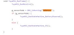
    @CMY I know this is unfortunate, but tmSensor code is now integrated with TuyaMCU driver, so it is still required to run, it's just the functions are in the other file. Everything should be okay once you run it:
    Code snippet showing a function that checks sensor mode status in integration with TuyaMCU.
    This is a legacy thing, that's because in the past tmSensor was totally separate but then it has turned out that we really have to merge them, so we ended up with the following aproach.

    Regarding this:
    
    Cons of using TuyaMCU:
    - no way to control main loop via BK7231N firmware (it will be power on only when TuyaMCU will do)
    

    Well, if someone wants, it's always possible to desolder the MCU and rig BK to control everything.
    Helpful post? Buy me a coffee.
  • #4 20922013
    CMY
    Level 2  
    p.kaczmarek2 wrote:
    Well, if someone wants, it's always possible to desolder the MCU and rig BK to control everything.


    Sure.
    But in this case better get this one "Door Sensor 19JWT-B (BK7231N)" https://www.elektroda.com/rtvforum/topic4028193.html#20906219

    Or you can
    - remove power controll Triac,
    - connect WiFi chip pin ground to Bat-
    - connect PowerControl output from TuyaMCU to some free WiFi pin to get wakeup trigger
    - extra option: connect someWiFi pin to TuyaMCY button (key) pin to have a option for wakeup TyuaMCU from WiFi. In this case WiFi can check door and battery status wherever you want.
  • #5 20922299
    p.kaczmarek2
    Moderator Smart Home
    Your concept is very interesting, @CMY , but wouldn't that reduce battery life, with both MCU and BK draining current slowly?
    Helpful post? Buy me a coffee.
  • #6 20923837
    CMY
    Level 2  
    p.kaczmarek2 wrote:
    Your concept is very interesting, @CMY , but wouldn't that reduce battery life, with both MCU and BK draining current slowly?


    I alredy cheked it.
    CMY wrote:
    For a test, I put BK7231N in to DeepSleep mode and all unit has ~20uA. So, It not so good as I was expected, and cutting power from WiFi chip is saving only ecreasing curent from 20uA to 13uA.

    So. Yes, 13uA vs 20uA.
    About +50% in deep sleep mode.
    It is all depends. But if i wanna do this, i will wakeup WiFi module like a every 5 min. And this will be more effected on power consumption.
  • ADVERTISEMENT
  • #9 21295061
    hojnikb
    Level 11  
    Would it be possible to remove tuyamcu entirely and use magnetic chip directly? And magentic chip would serve as a wakeup from deepsleep for wifi chip?

    I find that on my device, it's not working very reliably. Some times it wakes up and sends the state, sometimes it doesn't. ONENUO tuyaless versions work way more reliably.
  • ADVERTISEMENT
  • #10 21295477
    divadiow
    Level 34  
    I believe so. @p.kaczmarek2 has suggested such a step with other devices before though I've never actually progressed to trying. Is it basically trace the legs from TuyaMCU to each main component, button, led, ADC, magnet, remove TuyaMCU then solder from empty MCU pads to unused CB3S IOs?

    Added after 10 [minutes]:

    I guess magnet sensor gpio would be dInput or dInput_n in OBK config?
  • #11 21296021
    p.kaczmarek2
    Moderator Smart Home
    We've been planning to make such tutorial with @DeDaMrAz . It should be possible to convert TuyaMCU devices to Beken-only DeepSleep. The magned sensor could be dinput as @divadiow says, but you can also utilize the "DoorSensorWithDeepSleep" role and get automatic sleep behaviour, so you don't have to write autoexec.bat

    It should work, the only possible issue is that you might need to experimentally choose the digital input mode, maybe with pull up, or with pull down, and you also may need to choose the correct DSEdge option (there are 3 to choose from). I'd strong recommend to set Btn pin first as well so you can always wake up your device even if door sensor pin is not set correctly.
    Helpful post? Buy me a coffee.
  • #12 21299079
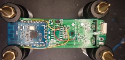
    divadiow
    Level 34  
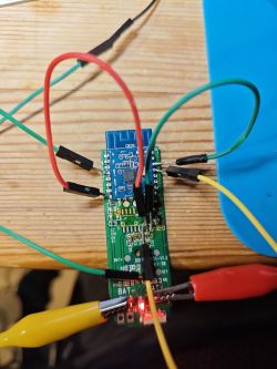
    my hacky TuyaMCUless prototype.

    not 100% sure of the LED/GND situation. And I don't know if there's a BAT_ADC/BAT_REL - could the MCU have done this measurement internally?

    Circuit board with marked pins for TuyaMCUless prototype.

    These assignments work in testing

    "7": "dInput;1",
    "8": "Btn;2",
    "14": "LED;2"

    Electronic circuit prototype with wires and LED on a PCB.

    (I damaged a couple of the MCU pads a while ago which is why the LED cable doesn't go from where labelled)
  • #13 21299315
    p.kaczmarek2
    Moderator Smart Home
    Nice, does deep sleep work as well?

    Also... your MCU was in SO8 case? That seems unusual for me. I saw many devices with SO16-etc MCUs.
    Helpful post? Buy me a coffee.
  • #14 21299423
    divadiow
    Level 34  
    p.kaczmarek2 wrote:
    Nice, does deep sleep work as well?


    yes. with:
    "7": "DoorSnsrWSleep;1",
    "8": "Btn;2",
    "14": "WifiLED;2"


    same wake with button. no additional DSEdge config. Closed/magnet = channel 1 value 0, open/no magnet = channel 1 value 1
  • #15 21301061
    p.kaczmarek2
    Moderator Smart Home
    So it's easier than I expected. Please consider making a separate guide for Smart Home Tutorials section.
    I see you also labeled pins on the MCU - so there is not BAT_ADC pin? I guess you may need to add your own resistors divider and utilize P23 (ADC) of Beken..

    We would need to either check all pins or get MCU datasheet to know if it's checking battery voltage internally.
    Helpful post? Buy me a coffee.
  • #16 21301091
    divadiow
    Level 34  
    p.kaczmarek2 wrote:
    Please consider making a separate guide for Smart Home Tutorials section

    could.do. I also have the solder-less flashing thing to do. I didn't want to distract from you and @DeDaMrAz's upcoming guide and I didn't document what I did in infinite detail ;)

    p.kaczmarek2 wrote:
    I see you also labeled pins on the MCU - so there is not BAT_ADC pin? I guess you may need to add your own resistors divider and utilize P23 (ADC) of Beken..


    I don't *think* there's a separate BAT_ADC. I don't think there are enough connected pins left out of the 8 for BAT_REL and ADC.
    A datasheet of the unmarked MCU would certainly be handy...

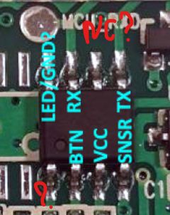
    I think the top one unlabelled is NC and the bottom left I'm not sure yet. I need to de-solder and clean-up the PCB to look again with fresh eyes.

    Close-up of an unmarked MCU with pin descriptions on a PCB.

    Added after 31 [minutes]:

    I wonder if we'll ever get to know about these unmarked MCUs. The D06, like TH01, S06 etc, are made by Shenzhen Forever Young Technology Co Ltd. - http://www.zz-power.com/cate-5703.html
    https://fccid.io/2ANK8-D06
    I see a couple of confidentiality request submissions so maybe the info not included in the FCC submissions include details about the MCU. Eg https://fcc.report/FCC-ID/2ANK8-C9000Q/3577071
  • #17 21330750
    hojnikb
    Level 11  
    divadiow wrote:
    p.kaczmarek2 wrote:
    Please consider making a separate guide for Smart Home Tutorials section

    could.do. I also have the solder-less flashing thing to do. I didn't want to distract from you and @DeDaMrAz's upcoming guide and I didn't document what I did in infinite detail ;)

    p.kaczmarek2 wrote:
    I see you also labeled pins on the MCU - so there is not BAT_ADC pin? I guess you may need to add your own resistors divider and utilize P23 (ADC) of Beken..


    I don't *think* there's a separate BAT_ADC. I don't think there are enough connected pins left out of the 8 for BAT_REL and ADC.
    A datasheet of the unmarked MCU would certainly be handy...

    I think the top one unlabelled is NC and the bottom left I'm not sure yet. I need to de-solder and clean-up the PCB to look again with fresh eyes.

    Close-up of an unmarked MCU with pin descriptions on a PCB.

    Added after 31 [minutes]:

    I wonder if we'll ever get to know about these unmarked MCUs. The D06, like TH01, S06 etc, are made by Shenzhen Forever Young Technology Co Ltd. - http://www.zz-power.com/cate-5703.html
    https://fccid.io/2ANK8-D06
    I see a couple of confidentiality request submissions so maybe the info not included in the FCC submissions include details about the MCU. Eg https://fcc.report/FCC-ID/2ANK8-C9000Q/3577071


    Could you provide schematic or some sort of tuturial on how to make it tuyaless ? Or at least which connections to bridge, so it would work without the MCU.
  • #18 21331027
    divadiow
    Level 34  
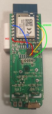
    I didn't do any more, but the steps to date can be boiled down to:

    -remove TuyaMCU with solder sausage method (demonstrated here https://www.youtube.com/watch?v=fSbeKwCCMHM)
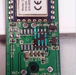
    -solder wires between these points:

    Circuit board with soldered wires marked with colors: VCC in red, LED in blue, SENSOR in green, BTN in yellow.
    -set pin assignments as in previous post

    Added after 9 [minutes]:

    that doesn't account for any battery measurement though
  • #20 21331500
    divadiow
    Level 34  
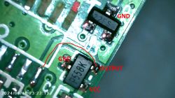
    bit more info. The P558K component is a hall-effect sensor. This is what the magnet needs to get close to

    Close-up of a circuit board with a marked P558K element, which is a Hall effect sensor.
  • #21 21350150
    daherbst85
    Level 4  
    I wish I had found this board/thread earlier—it would have saved me some work!
    I’m using the ZY-D02, which seems nearly identical to the D06 (mine uses a 2063P hall sensor and lacks the CB3S metal shield).


    In case someone else is looking for this, here a short summary:

    Power Management:
    The ZY-D02 uses hardware-based power control. Instead of firmware deep sleep, the TuyaMCU (8-pin IC) controls Q1 (a transistor or MOSFET) to physically cut the CB3S ground, completely powering it down.

    Wake-Up Behavior:
    The Hall sensor (2063P) detects state changes (magnet present/removed) and signals the TuyaMCU, which temporarily restores power to the CB3S ~ less than a minute (?).
    This makes it impossible to access the OpenBK AP unless you manually short the CB3S ground (pin 9) to the board ground, bypassing the power cutting Q1. Once bypassed the AP becomes accessible - the board draws 0.2W.
    (CB3S: https://developer.tuya.com/en/docs/iot/cb3s?id=Kai94mec0s076)

    TuyaMCU Communication of state changes
    The Hall sensor does not connect directly to the CB3S but communicates with it via the TuyaMCU over UART (TXD1 and RXD1 of the CB3S).
    A state change wakes up the CB3S by changing pin 3 of the MCU to high, which will turn on Q1 and restore the GND connection to the CB3S.
    The same can be achieved via the Reset button, which will pull down pin 2 of the MCU.
    As long as pin 3 of the MCU is high (3V), the MCU communicates the state via UART to the CB3S (MCU pin 5/7, CB3S pin 15/16).

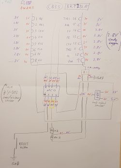
    The following drawing shows the traces I tracked by continuity measurements and the potentials on the previously mentioned components when the door sensor is awake and sleeping:
    Connection diagram of ZY-D02 door sensor with MCU and hall sensor.

    At this point I found this board/thread and like the proposal to remove the MCU and just solder some wires.
    However, I am wondering whether there is not a solution by decoding the UART signal. In that case the MCU would not have to be removed. Unfortunately, I don't know how any information sniffed from the UART communication could be integrated into OpenBK. I am new to this. Anyhow, maybe there is someone out there who might know?

    [edit]
    My MCU has a label (below): Y46D44A .... unfortunately, google doesn't know it

    Close-up of ZY-D02 electronic board with CB3S
    [/edit]
  • ADVERTISEMENT
  • #23 21350399
    divadiow
    Level 34  
    daherbst85 wrote:
    In that case the MCU would not have to be removed.

    100% yes but this thread morphed into how one would take the TuyaMCU out of the equation if desired. This would mean giving OpenBeken complete control over the device for features like deepsleep, rather than being at the mercy of the TuyaMCU.
  • #24 21352505
    daherbst85
    Level 4  
    Ok, I also did it this way and it works fine. The only thing I did differently was that I soldered pin 9 (GND) of the CB3S to GND instead of pin 8 (VCC) to the former MCU pin 3 pad, which switching the NPN transistor ...

    Anyhow, the remaining modification would be to read the battery voltage as you guys pointed out earlier.

    For that I used the internal voltage divider (R3:, 1k and R23, 10k). If you wired VCC to the former MCU pin 3 pad, it can be used directly (see my previous drawing).
    Then I soldered a wire between P23 / ADC3 / pin 2 (CB3S) and the two resistors.
    This should give me a multiplier of 1.1.
    Close-up of a circuit board with soldered wires and a CB3S module.
    (I removed the NPN transistor because I started melting wires when trying to solder the CB3S GND to the transistors GND ... it is not necessary to remove it - and you shouldn't if you don't add the GND connection ...)


    Somewhere I read that the maximum for the pin is 3.3V. (so it might be even fine without voltage divider?!?)

    "7": "DoorSnsrWSleep;1;0",
    "8": "Btn;1;1",
    "14": "LED;1",
    "23": "BAT_ADC;3"

    Since I am new to openBK, could someone advise me on setting this up in the interface?

    In the configure mode there is an BAT_ADC option, but I can't find any option to add a multiplier. For BAT_ADC the documentation says that 2400mV is the maximum and is measured as a reference to some other pin?!?
    When I change the option to ADC, no voltage is reported at all.
    Could anyone give me some advise?

    Thanks!


    [edit]
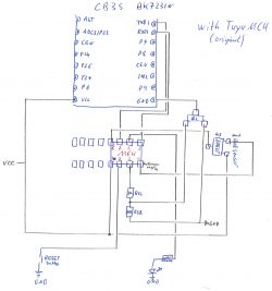
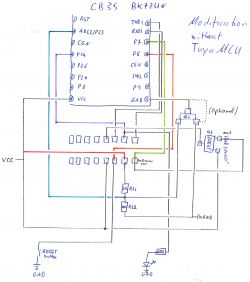
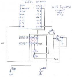
    @divadiow: I think there is a little mistake in your wiring diagram. The P14 / LED pin 4 (CB3S) should be wired to the former pad of the MCU pin 6 (second from the right), not 8. Otherwise the LED doesn't work.

    Wiring diagram for CB3S with Tuya MCU.
    Wiring diagram of a circuit with CB3S and BK7231N.
    [/edit]
  • #25 21353072
    spin55
    Level 17  
    This is the configuration of a door sensor with CB3S module:

    "pines": {
    "7": "Btn;0",
    "14": "BAT_Relay;3",
    "8": "DoorSnsrWSleep_nPup;1",
    "23" : "BAT_ADC;4",
    "26": "WifiLED;2"
    }

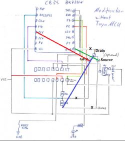
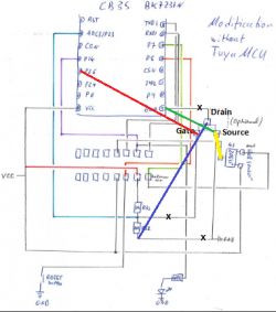
    P7 and P8 coincide, but you have P14 connected to the LED. You can change it to P26 and use P14 to connect it to the gate of Q1 (which is now connected to the junction of R31/R32).

    In my opinion, the correct connection of Q1 would be:

    Gate -> P14
    Source -> GND
    Drain -> R32

    When P14 High Q1 saturates and sets R32 to GND To read the battery level through P23.

    Or you can leave P14 as is and connect P26 to the gate of Q1. Then change:

    "pines": {
    "8": "Btn;0",
    "26": "BAT_Relay;3",
    "7": "DoorSnsrWSleep_nPup;1",
    "23" : "BAT_ADC;4",
    "14": "WifiLED;2"
    }


    Door sensor wiring diagram with CB3S module

    autoexec.bat:

    Battery_Setup 2000 3300 2.15 2400 4096
    //Battery_Setup 2200 2800 2.02 2400 4096
    Battery_Cycle 4
    addEventHandler OnHold 8 DSTime 2400
    DSTime 5
    DSEdge 0
  • #26 21353496
    daherbst85
    Level 4  
    Interesting, thanks!
    I was already wondering how an under voltage state could be avoided. So does the BAT_Relay take care of that via cutting the GND connection of the CB3S?
    Can I assume that the cutoff voltage is 2.5V (for two AAA batteries in series) or is it possible to set the level somewhere?

    So you suggest to cut the trace between R3:/R32 and the gate of Q1 and connecting it to P26, which makes perfectly sense!

    However, in case of an N-channel mosfet (Q1), the other two traces should be just fine as they are, aren't they (your X-es and new connections indicate a swap)?

    I am not sure what the autoexec.bat part means (I am new to OpenBK ... sorry).

    Thanks!

    (I think I damaged the mosfet when I removed it ... I have ordered more sensors and it might take a few weeks until I can try it.)
  • #27 21353795
    spin55
    Level 17  
    daherbst85 wrote:
    I was already wondering how an under voltage state could be avoided. So does the BAT_Relay take care of that via cutting the GND connection of the CB3S?


    BAT_Relay takes care of that by cutting the GND connection of Q1 through P26 controlling Gate. Pin 9 of CB3S has to be at GND permanently.

    daherbst85 wrote:
    Can I assume that the cutoff voltage is 2.5V (for two AAA batteries in series) or is it possible to set the level somewhere?


    Battery_Setup 2000 3300 2.15 2400 4096. Via parameter (2.15) corrects the R31-R32 divider ratio that is applied to P23 ADC.

    daherbst85 wrote:
    However, in case of an N-channel mosfet (Q1), the other two traces should be just fine as they are, aren't they (your X-es and new connections indicate a swap)?


    The X mean track interruption.

    daherbst85 wrote:
    am not sure what the autoexec.bat part means (I am new to OpenBK ... sorry).


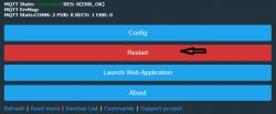
    autoexec.bat is a file that must be created from the Openbeken website to load the corresponding drivers.

    User interface of a web application with buttons: Config, Restart, Launch Web Application, About. Screenshot of a navigation menu with the Filesystem option highlighted. Screenshot of the Filesystem interface in the OpenBeken panel with the Create File button highlighted. Screenshot of the Openbeken interface with file editor, including autoexec.bat. Screenshot of the user interface with a Restart button.

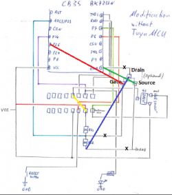
    And the Vcc connection is missing in the hall effect transistor.

    Electronic schematic with highlighted connections and breaks.
  • #28 21354059
    daherbst85
    Level 4  
    Thanks for the clarification! Very helpful!
    (Sidenote: Everything worked as I drew it before, just without battery)

    But I feel a few things got more confusing.
    I got that X means that the trace should be cut, but you draw 3 cut. One makes sense to me, the other two don't:

    spin55 wrote:
    daherbst85 wrote:
    I was already wondering how an under voltage state could be avoided. So does the BAT_Relay take care of that via cutting the GND connection of the CB3S?


    BAT_Relay takes care of that by cutting the GND connection of Q1 through P26 controlling Gate. Pin 9 of CB3S has to be at GND permanently.

    To me that sounds contradictory. You have drawn a line from Pin 9 (GND) of the CB3S to the pin that you labeled correctly as source (Q1), which is already at GND level. Like that Pin 9 is always grounded. Now, in case of an under voltage, P26 should go low at the gate and Q1 should interrupt the connection from the drain to the source. Since you labeled the connection of P9 to the drain with an X, the trace should be cut and the GND connection (as in the original circuitry with the MCU) will never be interrupted. Instead, now the GND connection of R23 (sorry I previously wrote R32) is interrupted (your second modification X to GND and blue line to drain). This would eliminate the GND connection of the voltage divider and ADC3/P23 would be floating. So I guess it would read random values (?!?) and won't cut power to the CB3S chip.

    In short: When the BAT_relay triggers/goes low, it wouldn't cut power, but (probably) just mess with the ADC pin(?).
    That's why I said that I don't understand why you swapped the connections and think/thought/don't understand, why the two traces were not fine as they were.
    Did you really mean it like that?

    Moreover, I think it might also not be the best idea to have R23 connected to GND via a mosfet, because the drain to source on resistance (RDS(on)) would add to R23 of the voltage divider, influencing the measurement.


    spin55 wrote:

    daherbst85 wrote:
    Can I assume that the cutoff voltage is 2.5V (for two AAA batteries in series) or is it possible to set the level somewhere?


    Battery_Setup 2000 3300 2.15 2400 4096. Via parameter (2.15) corrects the R31-R32 divider ratio that is applied to P23 ADC.


    Nice! Thanks!
    So here it would be:
    Battery_Setup 2000 3300 1.1 2500 4096 // ADC_min_mV, ADC_max_mV, multiplier, real_critical_mV, ADC_resolution // BAT_Relay triggers at real_critical_mV


    spin55 wrote:

    And the Vcc connection is missing in the hall effect transistor.

    Electronic schematic with highlighted connections and breaks.

    [/quote]

    Excellent that you noticed the missing connection, but it is not VCC that is missing. GND is missing! VCC is already connected to pin 1 of U3, pin 2 is the output, and pin 3 is connected to GND. I forgot the line in my drawing (sorry!). I updated my drawings and hope nobody uses the previous version. The pad of the former MCU pin 8 was GND too.
    The drawn connection would create a shortage and potentially fry something.

    Original (corrected)
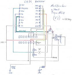
    Circuit diagram with CB3S module and MCU, showing power and ground connection modifications.

    Updated with Battery Relay P26 and Q1
    (notably, Q1 is cutting power in exactly the same way to the CB3S as the TuyaMCU did, just with the difference that P26 cuts power when it goes low instead of pin/pad 3 of the former MCU.
    Circuit diagram with CB3S and BK7231N modifications, including BAT_Relay.


    ... please challenge me ... I am not a professional, but just a hobbyist ...
  • #29 21354283
    spin55
    Level 17  
    daherbst85 wrote:
    Excellent that you noticed the missing connection, but it is not VCC that is missing. GND is missing! VCC is already connected to pin 1 of U3, pin 2 is the output, and pin 3 is connected to GND. I forgot the line in my drawing (sorry!). I updated my drawings and hope nobody uses the previous version. The pad of the former MCU pin 8 was GND too.


    Yes, you are right it was GND that was missing in the Hall transistor, not Vcc as I said. I'm sorry.

    The reason for adapting to the "standard" one is to correctly use the autoexec.bat drivers. Specifically, BAT_Relay would control Q1 to set GND R32 to read the battery level through P23 (ADC). I suppose this is floating until the measurement needs to be made so that there is no consumption when the device is not online. Please note that it is a battery powered device.

    I think PinDeepSleep is integrated into the drivers. To cause the chip to reset when there is a state change in P7/P8, you need to have GND connected. But in your setup, GND is controlled by Q1 and P26. And I don't think it will wake up because there is no GND and it cannot detect a change of state in P7/P8 (I have not verified this but it is evident that if you do not close a circuit to ground it is floating and there is no current consumption).

    Then, since you have to have P9 connected to GND permanently, take advantage of Q1 so that the drivers are compatible and work with the standard configuration.

    Circuit modification schematic of a transistor with marked connections.
  • #30 21354306
    daherbst85
    Level 4  
    true ... it is battery powered device and it goes to sleep, I forgot about that and considered my version as kind of a suicide switch and thought that as long as P26 is high, there is a ground. But well, that's probably a hen and the egg problem ... unless an external pull-up resistor is used ... and if that would work, the voltage divider would always take a sip from the battery ...

    Ok, I am going to try it once I got a new sensor or mosfet (next year).
    Thanks!

Topic summary

The discussion focuses on the Door Sensor D06 featuring the BK7231N WiFi chipset and a TuyaMCU (CB3S) module managing power and sensor inputs via serial interface. The TuyaMCU controls power to the WiFi module and handles the magnetic field sensor, with firmware updates requiring desoldering. Users explore the integration of tmSensor code with the TuyaMCU driver and the limitations of power control, noting that removing the TuyaMCU allows full BK7231N control and potentially improved deep sleep management. Several contributors share methods to bypass or remove the TuyaMCU, including soldering direct connections from the BK7231N to sensor components, reassigning GPIO pins for door sensor, button, LED, and battery ADC functions, and configuring OpenBeken firmware accordingly. The hall-effect sensor (P558K or 2063P) is identified as the magnetic sensor, with discussions on replacing it with a simple NO switch. Power management involves a transistor (Q1) controlled by the TuyaMCU or firmware to cut power to the WiFi module for deep sleep, with detailed schematics and wiring modifications to enable battery voltage measurement via ADC and to maintain proper ground connections. MQTT integration with Home Assistant is addressed, including configuration of MQTT topics, payloads, and discovery, with troubleshooting for sensor state reporting and battery voltage. The thread also covers challenges in wake-up reliability, firmware roles like DoorSensorWithDeepSleep, and the potential for a tutorial on converting TuyaMCU-based sensors to TuyaMCU-less operation with OpenBeken firmware for enhanced control and power efficiency.
Summary generated by the language model.
ADVERTISEMENT