FAQ
TL;DR: OTA wrote 794,045 bytes on first boot; "we see OTA process on first boot". Flash OBK by merging bin+rbl, map pads to CH341A, and back up the 4 MB flash. For hardware hackers needing flash backups, OTA layout, and Tuya pairing notes. [Elektroda, divadiow, post #21570898]
Why it matters: It shows how to safely dump, flash, and OTA‑upgrade BK7252 A9 camera PCBs without bricking, using low‑cost tools.
Quick Facts
- SoC/PCB: BK7252UQN68 on SC-10024 v1.0.0 A9-size PCB, 18‑pin camera FFC, two buttons, red and blue/green LEDs. [Elektroda, divadiow, post #21557995]
- Flash: XTX XT25F32B SPI, 32 Mbit (4 MB), SPI ID 0x0B4016; NeoProgrammer detects and dumps. [Elektroda, divadiow, post #21557995]
- UART/Pairing: 115200 baud on TX1; device advertises AP SmartLife‑2640 and pairs in Tuya app. [Elektroda, divadiow, post #21557995]
- OTA style: Realtek‑like ping‑pong OTA (OTA1/OTA2); ty_ipc_lite_sdk appears in firmware. [Elektroda, divadiow, post #21557995]
- Firmware: OpenBK7252_QIO__7231u_t_c1b0ac146bf0.bin boots OBK; the Tuya_QIO variant boots BL only. [Elektroda, divadiow, post #21557995]
What is this Taobao BK7252 A9 camera PCB and its hardware layout?
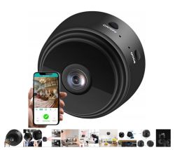
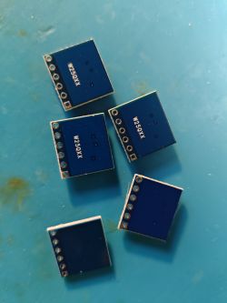
It’s a bare A9-style camera PCB marked SC-10024 v1.0.0 using a BK7252UQN68. It includes an 18‑pin camera connector, two buttons, and two LEDs (one red and one blue/green two‑tone). No camera module, battery, or case ship with it. [Elektroda, divadiow, post #21557995]
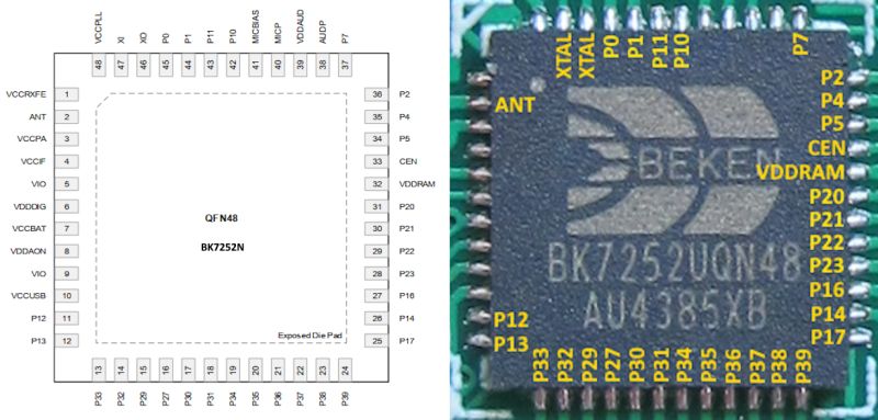
How do I wire the test pads to a CH341A to back up the SPI flash?
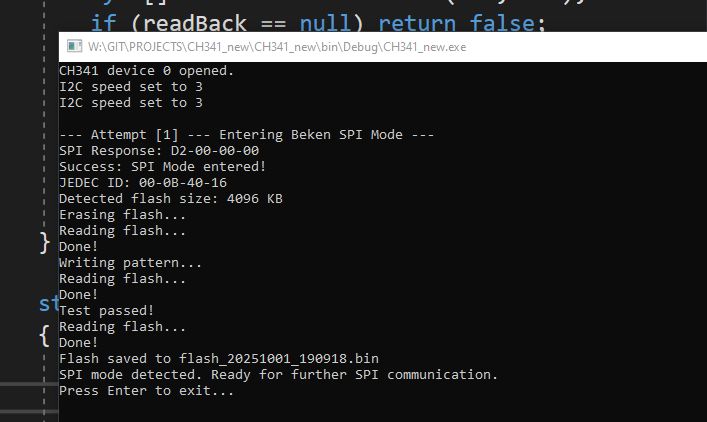
Pad map: CE/CEN→D2, SCK→SCK, CSN→CS0, SI→MOSI, SO→MISO, GND→GND. Then use Beken SPI mode with a CH341A and NeoProgrammer. How‑To: 1) Solder flying leads to pads. 2) Enter Beken SPI mode and power the board. 3) Detect XTX XT25F32B and dump the 4 MB image. [Elektroda, divadiow, post #21557995]
What flash chip and capacity does it use?
The board carries an XTX XT25F32B SPI NOR. Capacity is 32 Mbit (4 MB). Reported SPI ID is 0x0B4016. NeoProgrammer recognizes it reliably for dumps. [Elektroda, divadiow, post #21557995]
What UART settings should I use and what indicates a healthy boot?
Use 115200 baud on TX1. A healthy boot shows BK7251_x logs, Tuya initialization, BLE advertising, and AP start as SmartLife‑2640. You’ll also see Wi‑Fi and watchdog initialization entries and LED status changes in logs. [Elektroda, divadiow, post #21557995]
How can I flash OpenBK7252 and trigger the OTA upgrade on first boot?
Merge OpenBK7252_QIO7231u_t_c1b0ac146bf0.bin with OpenBK72527231u_t_c1b0ac146bf0.rbl at 0x132000 and flash from 0x0. On first boot, the OTA engine writes 794,045 bytes to the app partition, then boots OBK. Watch serial logs to confirm erase and write progress. [Elektroda, divadiow, post #21570898]
Does OTA work on this A9 BK7252 board?
Yes. “So, OTA works.” Users report success, though initial SPI flashing may be needed to stage images. Using the default A9 bootloader helped in testing. [Elektroda, insmod, post #21570913]
Why do OTA uploads via the web GUI fail with “malloc failed”?
Logs show OTA attempts via the web and GUI ending with “malloc failed.” A practical workaround is pre‑staging the RBL at 0x132000 and flashing a merged image so the device upgrades itself on first boot. [Elektroda, divadiow, post #21570898]
What OTA layout and addresses are involved on this board?
The boot log shows a ping‑pong scheme erasing the download RBL at 0x132000. Combining the .bin base and .rbl at that offset enabled the on‑boot OTA to rewrite the app partition. [Elektroda, divadiow, post #21570898]
How far can the built‑in UART preset read, and how do I dump the full 4 MB?
The standard BK7252 preset read stops around 2 MB. Use the EF custom read from 0x11000 via TX2/RX2 to reach the end, or use CH341A SPI to dump the full 4 MB directly. [Elektroda, divadiow, post #21557995]
Which OpenBK builds boot correctly on this board?
OpenBK7252_QIO7231u_t_c1b0ac146bf0.bin boots into OBK. The OpenBK7252_Tuya_QIO7231u_t_c1b0ac146bf0.bin shows bootloader output but no app, ending with an ARM anomaly on jump. [Elektroda, divadiow, post #21557995]
Can I pair it with Tuya and view its data model (DPs)?
Yes. It pairs and reports device details (firmware 1.0.4). The model exposes DPs such as basic_indicator, basic_nightvision, sd_status, sd_format, record_switch, device_restart, and others useful for IPC features. [Elektroda, divadiow, post #21557995]
Is an SDK available for this board or Tuya IPC?
The seller did not provide the SDK. However, public TuyaOS IPC demo archives exist (tuyaos_demo_ipc versions 1.0.x through 1.1.50) hosted on Tuya’s Airtake storage. [Elektroda, divadiow, post #21570227]
How do I enter Beken SPI mode and verify flash access?
After wiring the pads, power the board and use the Beken SPI Python tool with CH341A. NeoProgrammer should detect XTX XT25F32B (ID 0x0B4016) and allow read/write operations, confirming SPI access. [Elektroda, divadiow, post #21557995]
What LEDs and buttons exist, and can I control indicators from Tuya?
The PCB has two buttons and two LEDs: a single red and a blue/green bi‑color. The Tuya DP basic_indicator toggles the status LED behavior from the app’s settings page when paired. [Elektroda, divadiow, post #21557995]
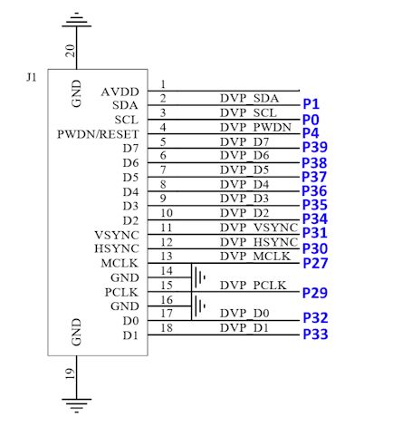
Should I remove series resistors when repurposing lines as GPIOs?
Yes. Remove the series resistors to avoid unintended loading and get clean GPIO behavior. As an expert noted, “it’s better to remove those resistors.” [Elektroda, p.kaczmarek2, post #21617875]


