logo elektroda
logo elektroda
X
logo elektroda

[Tutorial] Flashing OpenBK via OTA using tuya-cloudcutter

ferbulous 19359 37
ADVERTISEMENT
  • Download the tool here
    https://github.com/tuya-cloudcutter/tuya-cloudcutter

    Before using the script, verify your device tuya-firmware version using the tuya/smartlife app
    and download the correct firmware for your device chip (T or N). The chip would not boot if wrong firmware version is flashed on it and it would require using serial method to re-flash it again with the correct firmware.

    Steps:
    1. Start the script (run_flash.sh)
    2. Select the firmware that you have downloaded earlier to the custom-firmware directory.
    3. Select your profile that matches with the tuya-firmware version.
    4. Reset your device to AP mode (if profile matches, A-xx prefix would show up after it gets reset the 2nd time)
    5. Reset your device again for the OTA flashing,


    For no (3), if your device is not supported, then you would need to make dump of your device firmware using bk7231tools and submit a github request for profile creation.
    There's also Lightleak app that can obtain firmware dump wirelessly. I've had some success with T device but not N yet

    [Tutorial] Flashing OpenBK via OTA using tuya-cloudcutter

    Alternatively you could still generate your own profile using hexomatic with this batch script

    Spoiler:
    
    bk7231tools dissect_dump -e -O %1 %1.bin
    pushd %1
    ..\haxomatic.py %1_app_1.00_decrypted.bin
    ..\parse_storage.py %1_storage.json
    ..\parse_app.py %1_app_1.00_decrypted.bin
    mkdir extracted
    move *.txt extracted\
    popd
    assemble_universal.py %1

    save as do_magic.bat

    On windows rename full dump .bin to device-manufacturer_device-name.bin and run it like this
    do_magic.bat device-manufacturer_device-name


    It should generate these files

    [Tutorial] Flashing OpenBK via OTA using tuya-cloudcutter

    Copy the last two JSON files to a subdirectory in device-profiles.
    Rename each to device.json and profile.json, respectively
    And execute run_flash.sh <wifi adapter name> <your subdirectory name>

    Cool? Ranking DIY
    About Author
    ferbulous
    Level 18  
    Offline 
    ferbulous wrote 417 posts with rating 55, helped 8 times. Been with us since 2022 year.
  • ADVERTISEMENT
  • #2 20339866
    nielspiersma
    Level 9  
    Excellent tutorial. I want to share that it is essential to double-check the real chip on the PCB. Tuya has been shipping out CB2S labelled PCB's with BK7231Ts.
    [Tutorial] Flashing OpenBK via OTA using tuya-cloudcutter
    [Tutorial] Flashing OpenBK via OTA using tuya-cloudcutter
    So, removing the label and double-checking if you run into flashing issues is imperative.
  • ADVERTISEMENT
  • #3 20340977
    ferbulous
    Level 18  
    nielspiersma wrote:
    Tuya has been shipping out CB2S labelled PCB's with BK7231Ts

    Thanks for highlighting that, probably won't notice if I never open the metal case which I rarely do
    I think I'll edit my post to recommend running 'run_detach' script first just to verify which chip the device is running on.
  • #4 20451412
    mcheibani
    Level 4  
    Thanks for the great tutorial. The wireless method is very easy and beginner friendly (like myself). It will help a lot of us disconnect from the Tuya cloud.
    I tried it in a couple of devices and it worked with one but the other one failed to boot after flashing which is likely caused by flashing the wrong firmware. Is there a way to find out which chip I have (N or T)? I find it a bit confusing. I have for example a MOES dimmer module (105B). In the OpenBeken device list page, it shows that the device has the T version. But in cloudcutter device profiles, if I select manufacturer and profile, it suggestes that it's N. I opened up the device and I see Model: CB2S. Is there a way to confirm which chip I have?
  • #5 20451489
    nielspiersma
    Level 9  
    We found that tuya is sending out pcbs with wrong labeling. So the only way to know 100% sure is by finding the chip and reading it.

    Other method is just try on error. The good thing is that it is almost impossible flashing T on N or vise versa.

    Niels
  • #6 20451509
    mcheibani
    Level 4  
    Thanks for the reply. The problem is that I have caused a device not to boot by flashing the wrong firmware. I had a 16a mini switch that I flashed with the N firmware and it didn't boot after the flash process completed. Afterwards I found out that it has a T chip. I need now to flash it with the serial method for which I don't have the tools.
  • #7 20451541
    nielspiersma
    Level 9  
    Okay,

    That is kinda new for me. I never was able flashing an T to N or vice versa.

    Am I correct in assuming you used tuya cloud cutter for initial flash and then a flash with OTa resulting in a bricked device?

    Afaik it is not possible flashing the wrong firmware during cloud cutter...

    Niels
  • #8 20451565
    mcheibani
    Level 4  
    nielspiersma wrote:
    Am I correct in assuming you used tuya cloud cutter for initial flash and then a flash with OTa resulting in a bricked device?


    I meant that I flashed it the initial time with the wrong firmware using cloudcutter.
    nielspiersma wrote:
    Afaik it is not possible flashing the wrong firmware during cloud cutter...

    Hmm. the device stopped working right after flashing with cloudcutter. I assumed that it was because of the wrong firmware.
  • #9 20451634
    nielspiersma
    Level 9  
    Hmm. That is new for me.

    I initially had a problem with a wrongly labelled N version that was actually a T. It was never possible for me to flash it with the N version until I tried the T version that magically worked.

    So I would recommend trying to boot it again in recovery mode and try flashing it again.

    Getting the device into recovery mode differs from device to device. My best results are. Power on. Wait 2 seconds. Keep button pressed for 7 to 8 seconds. Release and press again for 6 to 8 seconds. Usually it is in open access point mode and you should be able to run cloudcutter again.


    Niels
  • #10 20451669
    Zain00
    Level 10  
    nielspiersma wrote:
    We found that tuya is sending out pcbs with wrong labeling. So the only way to know 100% sure is by finding the chip and reading it.

    Other method is just try on error. The good thing is that it is almost impossible flashing T on N or vise versa.

    Niels


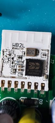
    A few months ago I had AVATTO Bulb that came with WB2L module .
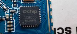
    Under the metal shield I found C-chip CC8000 instead of BK7231T
    I don’t know if it's the same chip under a different name or Tuya was trying other chips than Beken

    [Tutorial] Flashing OpenBK via OTA using tuya-cloudcutter
  • #11 20451867
    ferbulous
    Level 18  
    @mcheibani

    To avoid this, i would recommend initially using the detach script (just cloudcut from tuya).
    If N profile works, then it has to be N device
    Same goes with T device

    Added after 4 [minutes]:

    @Zain00
    Well that’s something new
    That’s not even a beken chip, i’ve bought one before with the exact same chip (CC8000) and i ended just selling that one.
    The pinout was odd so I wasn’t sure if i could just swap it with esp
  • #12 20452873
    mcheibani
    Level 4  
    nielspiersma wrote:
    So I would recommend trying to boot it again in recovery mode and try flashing it again.


    Thank you! This helped solve the issue for my old switch that I thought will need to be reflashed using the serial/soldering method. I tried again to put it in recovery mode and was able to flash it with the correct firmware.

    Added after 1 [minutes]:

    ferbulous wrote:
    @mcheibani

    To avoid this, i would recommend initially using the detach script (just cloudcut from tuya).
    If N profile works, then it has to be N device
    Same goes with T device

    Thank you for the response. I will try that.
  • ADVERTISEMENT
  • #13 20456614
    p.kaczmarek2
    Moderator Smart Home
    WB2L with CC8000? Can you try doing a flash read of that? Or at least try to get UART log?
    @Zain00
    Helpful post? Buy me a coffee.
  • #14 20456877
    Zain00
    Level 10  
    This picture was taken 5 months ago.
    Sadly, I can't find the module
  • #15 20457002
    p.kaczmarek2
    Moderator Smart Home
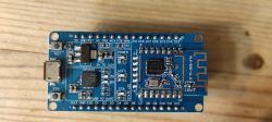
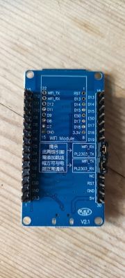
    Yea, same here... I once ordered BK7231U dev board from aliexpress and also got CC8000. I am not sure if I tested it more... I must find my module and test.

    https://www.elektroda.pl/rtvforum/find.php?q=CC8000
    https://www.elektroda.com/rtvforum/find.php?q=CC8000
    Helpful post? Buy me a coffee.
  • #16 21025914
    akosschneemaier
    Level 6  
    Hello, I ran into a modul with CC8000, it is in a modul made by Leedarson based on the MAC address. On their website I was only able to find the ESP8266 version which has the same form factor and pinout then my CC8000 module.

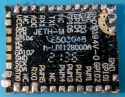
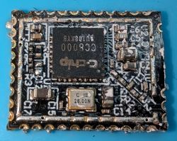
    Here are some pictures of my modul:
    Close-up of a CC8000 electronic module on a blue background.
    Close-up of a CC8000 module with visible components on a circuit board.

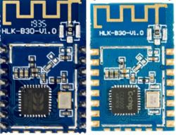
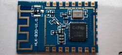
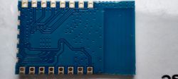
    I checked the serial ports and it seems to be pin compatible with BK7231. This is also confirmed by looking at pictures of HLK-B30 modules with Beken and CC chips. The PCBs are identical, thus I assume the pinout is identical too:
    Two electronic modules HLK-B30-V1.0, the left one with chip 1935, the right one with chip CC8000.

    Can it be that the programing is the same? What is the best way to test it?

    Thanks
  • ADVERTISEMENT
  • #17 21025919
    divadiow
    Level 34  
    Very interesting. I wonder what the UART boot output is and if you can dump firmware
  • #18 21025964
    akosschneemaier
    Level 6  
    I will add the UART output of the modul when I have some time to wire it up.

    How should I try to dump the firmware? Are there any special suggestions, instructions?

    thanks
  • #20 21025973
    p.kaczmarek2
    Moderator Smart Home
    It is Beken but it most likely has different encryption keys. I've been researching it some time ago. Maybe bootloader is different. Make sure to get full flash backup first.
    Helpful post? Buy me a coffee.
  • #21 21026054
    akosschneemaier
    Level 6  
    Which serial port should I use for the backup? The chip has 2 of them.

    Thanks
  • #22 21026165
    divadiow
    Level 34  
    Rx/tx0 I think? Not the set you get the boot log from.

    Added after 22 [minutes]:

    But anyway, if you capture log out first then you know it's the other pair to flash
  • #23 21026597
    p.kaczmarek2
    Moderator Smart Home
    To be more precise, flashing port is TX1/RX1. TX1/RX1 is first UART port (UART1), which can be used to read and write the firmware and TX2/RX2 is second UART port (UART2) which is used as debug log output (on TX2).

    Once OBK is flashed, you can reconfigure the logger to also use TX1 (UART1) for log output instead of TX2.
    Helpful post? Buy me a coffee.
  • #25 21026992
    akosschneemaier
    Level 6  
    >>21026597

    Unfortunatelly I cannot get any life out from the module. I tried both serial ports and different power supplies (just make sure it is not a voltage issue).

    1. A may killed the module during the hotair removal process.
    2. There is something on the origianal board which it checks before booting.

    Most of the pins are not connected on the original main pcb. Examining the board with the cc8000, I see that R3 is missing and it is connected between the VCC and the CE pin, so I think the CE pin should be pulled high to enable the chip. If this is correct than I maybe able to correct it with pulling the CE pin to VCC with a resistor. What should be the value for this resistor? I normally use 4.7k.

    Thanks
  • #26 21027769
    divadiow
    Level 34  
    Ooh. I have a WB2L device I haven't explored yet. Maybe there's a CC8000 under the shield

    WB2L module on a circuit board with visible capacitors and other electronic components.

    Added after 7 [minutes]:

    oh boring

    WB2L electronic module with visible components and connectors.

    Added after 4 [minutes]:

    akosschneemaier wrote:
    What should be the value for this resistor? I normally use 4.7k.


    not sure tbh. I know we use 10k when pulling boot high on BL602 chips to enable flashing mode.

    Added after 10 [minutes]:

    I also note that a user has mentioned a 10k resistor fitted by factory from a pin to a push button to pull high here https://www.elektroda.com/rtvforum/topic4028193.html#20906219
  • #27 21029091
    akosschneemaier
    Level 6  
    Thanks!

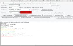
    I connected the CE to VCC and the device started to boot. However the boot on UART0 is boring. This is the only output I get:
    
    enter [cc8000::V2.3.72::V2.04.51] main ok ; tick=57
    -----rw_main task init----
    -----rw_main  start----


    Tried BKFlasher to do a backup but it fails with both with T and N:
    
    Backup name has not been set, so output file will only contain flash type/date.
    Starting read!
    Now is: Monday, April 1, 2024 8:26:52 PM.
    Flasher mode: BK7231T
    Going to open port: /dev/ttyUSB0.
    Serial port open!
    Getting bus... (now, please do reboot by CEN or by power off/on)
    Getting bus failed, will try again - 0/100!
    Getting bus success!
    Going to set baud rate setting (115200)!
    Going to start reading at offset 0x00...
    Reading 0x00... failed with serial.BytesToRead 3999 (expected 4111)
    The beginning of buffer in UART contains 040EFF01E0FCF40610090000002000AC data.
    Failed! There was no result to save.


    Now is: Monday, April 1, 2024 8:34:32 PM.
    Flasher mode: BK7231N
    Going to open port: /dev/ttyUSB0.
    Serial port open!
    Getting bus... (now, please do reboot by CEN or by power off/on)
    Getting bus failed, will try again - 0/100!
    Getting bus success!
    Going to set baud rate setting (115200)!
    Will try to read device flash MID (for unprotect N):
    failed with serial.BytesToRead 0 (expected 15)
    The beginning of buffer in UART contains  data.
    Failed to read device MID!
    Going to start reading at offset 0x00...
    Reading 0x00... failed with serial.BytesToRead 1433 (expected 4111)
    The beginning of buffer in UART contains 656E746572205B6363383030303A3A56 data.
    Failed! There was no result to save.


    Screenshot of BK7231 Easy UART Flasher application with Reading failed error message.
  • #28 21037855
    divadiow
    Level 34  
    Looking around though, the cc8000 looks to be a rebadged BK7231U, not N or T. So probably won't work with OBK? Won't it need a different SDK/fork/whatever to build a new fw?
  • #29 21039567
    divadiow
    Level 34  
    divadiow wrote:
    I'm going to order one to see what I get! https://www.aliexpress.com/item/4000981643389.html


    some pics I took before I started playing and later killed the chip. Didn't get anywhere with flashing. Have ordered another module (with pins!) and the dev board.

    Electronic module HLK-B30 with CC8000 chip on a blue PCB Blue electronic module with visible circuit traces and soldering points. Close-up of C-chip CC8000 integrated circuit on a blue electronic board.

    https://www.aliexpress.com/item/1005005878342693.html

    Added after 25 [minutes]:

    Maybe this should be its own topic about BK7231U/CC8000

Topic summary

The discussion revolves around flashing OpenBK firmware via OTA using the Tuya Cloudcutter tool. Users emphasize the importance of verifying the actual chip on the PCB, as Tuya has been known to ship devices with incorrect labels. The flashing process involves downloading the correct firmware, running a script, and ensuring the device is in AP mode. Several users share experiences of flashing issues, particularly related to incorrect firmware versions (T vs. N chips), and the challenges faced when devices fail to boot. Solutions include using the detach script to identify the chip and attempting recovery mode for re-flashing. The conversation also touches on the CC8000 chip, which appears to be a rebadged BK7231U, and the need for different firmware for these variants.
Summary generated by the language model.
ADVERTISEMENT