logo elektroda
logo elektroda
X
logo elektroda

CB2S/WB2S cheap dev board made from NiceMCU_WB3S_V1 (replace WB3S with WB2S/etc)

p.kaczmarek2 1542 11
ADVERTISEMENT
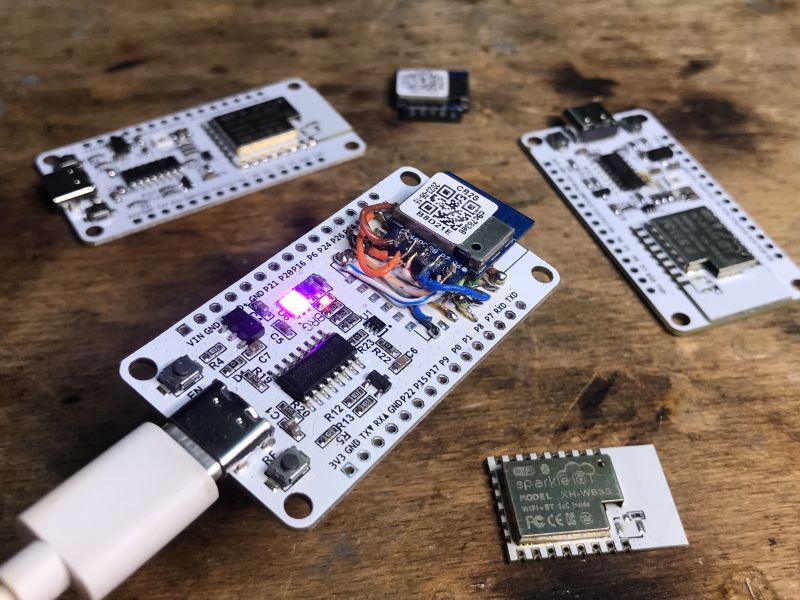
  • NiceMCU_WB3S_V1 board with mounted CB2S module and connected wires.
    NiceMCU_WB3S_V1 is a very cheap (possible to buy for as low as 1-2$) Beken development board. It comes with BK7238 chip, but with some soldering it's also possible to very easily swap the BK7238 module with any classic Tuya WB2S or CB2S and still get correct GPIO markings. Here I will show you how I've done it.

    The basic idea is to just get WB2S/CB2S, get some Ethernet wires and just solder the pads to their correct places, so the GPIO names on the board are correct.

    So first, you obviously need NiceMCU_WB3S_V1 board, which has been already discussed here:
    NiceMCU XH-WB3S BK7238 Flashing, Testing, Pinout, Development, Porting
    You can get it for as low as about 1$ when you create new account:
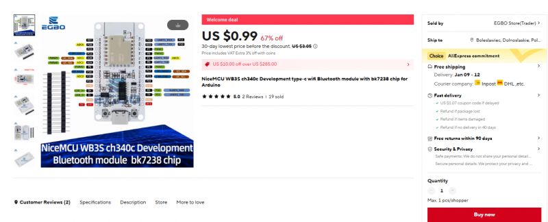
    NiceMCU WB3S development board with BK7238 Bluetooth module, displayed on an online store page.
    Then you need to do a hot air BK7238 module removal, just like in my previous dev board hack (NodeMCU):


    By the way, here is pinout of BK7238 module:
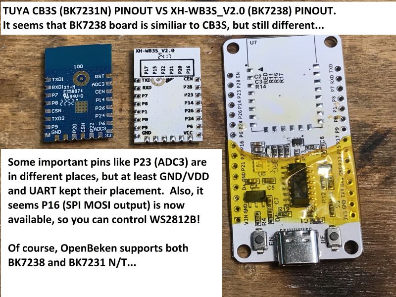
    Comparison of pinouts for TUYA CB3S (BK7231N) and XH-WB3S_V2.0 (BK7238).
    Here is the other side view:
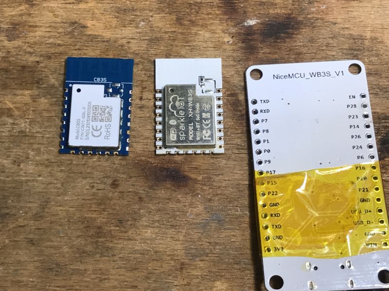
    Three different electronic modules lying on a wooden table, including NiceMCU_WB3S_V1 with visible pin labels.
    Ok, with this information, we can just mark which pin goes where:
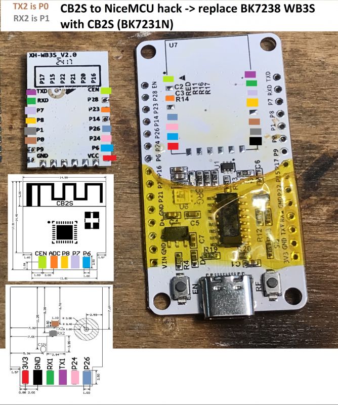
    NiceMCU_WB3S_V1 board with replaced CB2S module
    In this particular case, I've used BK7231M (not N) CB2S, but it does not matter, pins are the same.
    I'm using such wires:
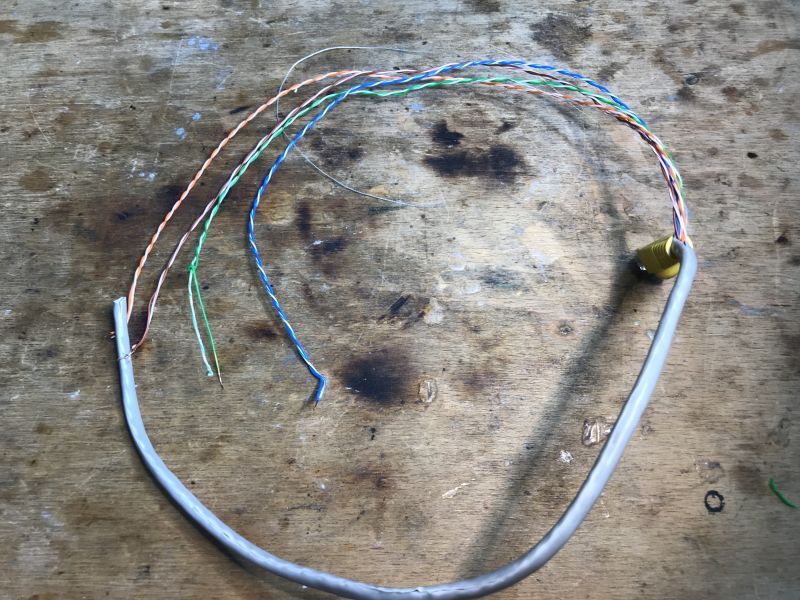
    Several colored Ethernet wires on a workbench.
    Soldering should be very easy. Just follow the simple guidelines:
    - always keep soldering iron tip clean
    - use flux and Pb soldering iron (as it has lower melting point)
    - first apply solder separately to wire and to the pad, then solder wire to the pad
    - make sure to strip insulation from wires first
    - avoid bending wires repeatedly or they may snap
    While soldering wires, make sure to check where they should go and chose the best wire orientation:
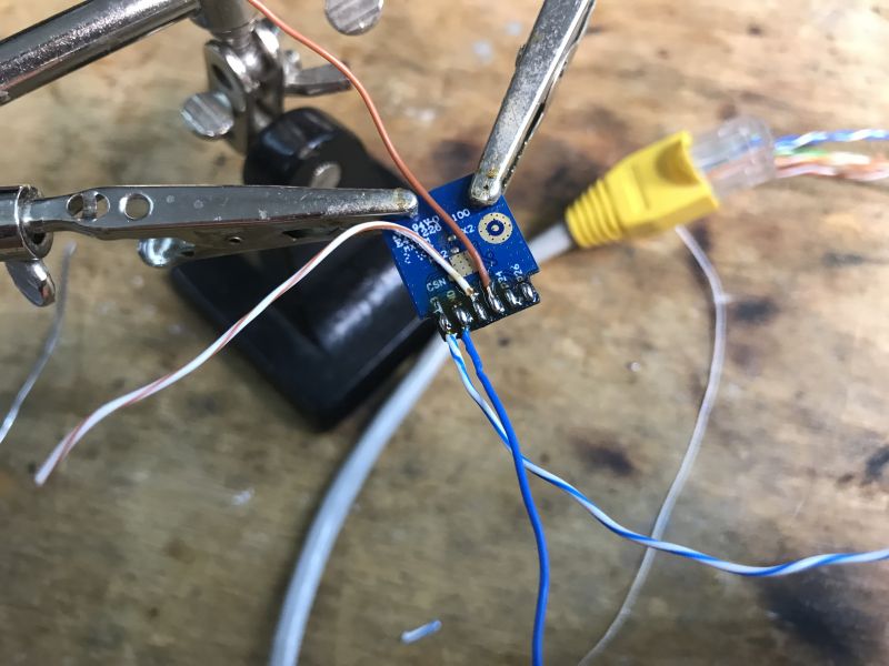
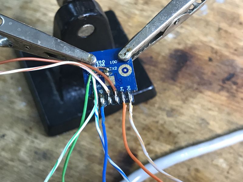
    NiceMCU_WB3S_V1 board with soldered Ethernet wires Development board with attached Ethernet wires in a holder.
    Placement time:
    NiceMCU_WB3S_V1 development board with soldered wires.
    Some little corrections:
    Close-up of NiceMCU_WB3S_V1 board with attached wires.
    Initial test with our flasher:


    Almost ready:
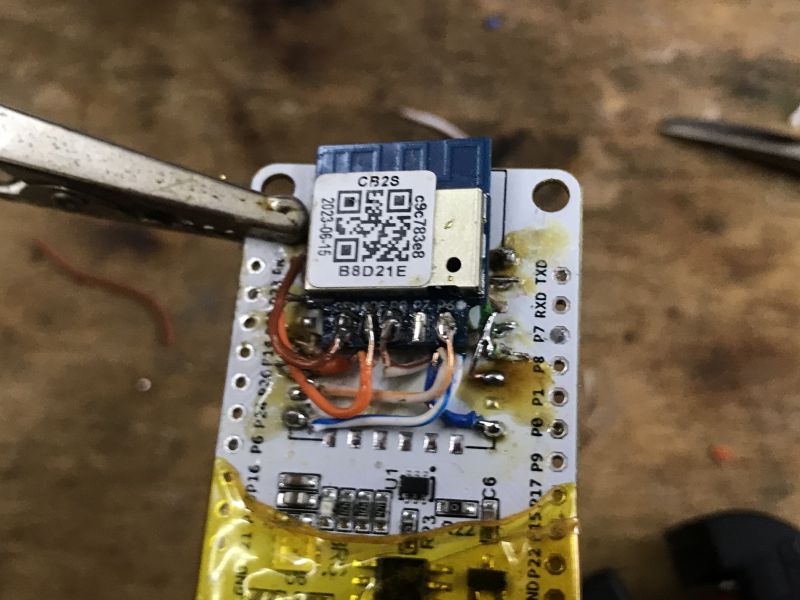
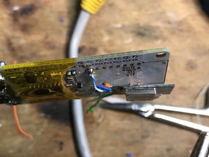
    Close-up of NiceMCU_WB3S_V1 board with attached CB2S module.
    Complete product:
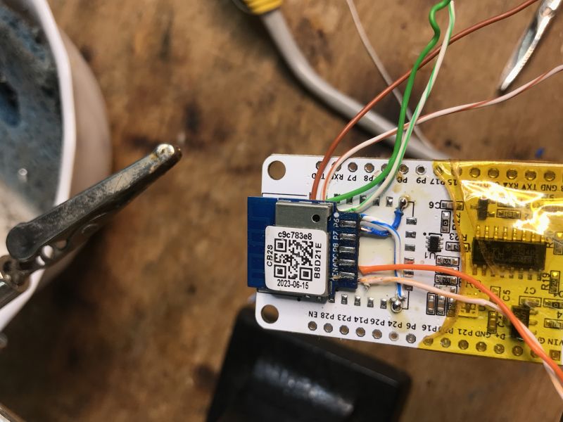
    NiceMCU_WB3S_V1 board with mounted CB2S module and connected wires.

    Now all of CB2S pins (even RX2 and TX2, which are on module back) are routed to their correct places on the board. Futhermore, the onboard LED also works (PWM0 and PWM4 pins seems to control it).

    This way our new CB2S dev board is complete and it's better than NodeMCU hack because the markings on the board (like P9, P1, etc, TX, etc) are correct, so it's easier to quickly assembler a test setup with it. Now it's ready to be used for some OpenBeken development and testing.

    PS: There is also our CB2S/WB2S to CB3S/WB3S converter available, which we've shown here, but it does not route RX2/TX2 and the module is perpendicular to mother board, which increases it's height greatly...

    Cool? Ranking DIY
    Helpful post? Buy me a coffee.
    About Author
    p.kaczmarek2
    Moderator Smart Home
    Offline 
    p.kaczmarek2 wrote 11822 posts with rating 9927, helped 564 times. Been with us since 2014 year.
  • ADVERTISEMENT
  • #2 21366157
    rufus4
    Level 10  
    Nice mod! That's quite useful for quick tests and experiments.
    Are these Beken boards and chips only sold directly to companies assembling it to electronic goods for the final market?
    I do really wonder to not find chips and boards from Beken on aliexpress. Actually I would like to buy some CB2S boards. They are more efficient on energy consumption than Espressiv processors.
  • ADVERTISEMENT
  • #3 21366615
    p.kaczmarek2
    Moderator Smart Home
    We've tried ordering those Tuya modules once, can you guess what firmware they had on them when their arrived?
    Here is our experience:
    Our experience with buying "brand new" Tuya modules like CB2S, CB3S, WB2S (BK7231T, BK7231
    How more efficient are they, how did you test it? It's interesting.

    PS: searching for Tuya CBU:
    Screenshot of search results for tuya cbu on a shopping website, displaying various Tuya CBU modules and development boards.
    Helpful post? Buy me a coffee.
  • ADVERTISEMENT
  • #4 21366887
    rufus4
    Level 10  
    I have LoraTap chines curtain switches with additional RF board. The old ones came with TYWE2S/ESP8285, new ones with CB2S/BK7231N.
    They are identical, only the board with the microprocessor changed.
    Both got the "same" ESPHome FW with the same scripts flashed and I mesured the AC power from the hole unit with a good clamp meter giving reliable results.
    (note: one is pure ESPHome and the other is with LibreTiny-ESPHome)

    CB2S/BK7231N
    6,5mA = 1,5W WiFi on
    5,7mA = 1,3W WiFi off

    TYWE2S/ESP8285
    8mA = 1,85W WiFi on +23%
    6,4mA = 1,47W WiFi off +12%

    ESP8285 has got high power spikes, so I did try to get the average. I could mesure more then 10mA with "WiFi on", with "WiFi off" its much more constant.
    BK7231N's power consumption is more constant. Conspicuous that it uses much (at min. 23%) less power with WiFi on in comparison to the ESP8285.

    Spoiler:

    
    esphome:
      name: cb2s-2
      friendly_name: cb2s 2
    
    # turn wifi off, set (api: --> reboot_timeout: 0s) to prevent bootloop  (!!!not working on CB2S!!!)
      on_boot:
         then:
           - delay: 300s
           - wifi.disable:
    
    bk72xx:
      board: cb2s
    #  restore_from_flash: false (!!!not working on CB2S!!!)
    
    # Enable logging
    logger:
    
    # Enable Home Assistant API
    api:
      #turn wifi off, set (api: --> reboot_timeout: 0s) to prevent bootloop
      reboot_timeout: 0s
    
      encryption:
        key: "xxx"
    
    ota:
      - platform: esphome
        password: "xxx"
      
    wifi:
      #wifi powersafe mode: NONE,LIGHT,HIGH
      power_save_mode: HIGH
    #  fast_connect: true  
    

    ...
    
    esphome:
      name: "TYWE2S"
      friendly_name: "TYWE2S"
    
      #turn wifi off, set (api: --> reboot_timeout: 0s) to prevent bootloop
      on_boot:
         then:
           - delay: 300s
           - wifi.disable:
       
    #external_components:
    #  - source: github://ssieb/esphome@wifioff
    #    components: [ wifi ]
    #    refresh: 1min
     
    
      #esp8266 1MB flash
    esp8266:
      board: esp8285
      restore_from_flash: false
    
    # Enable logging
    logger:
    
    # Enable Home Assistant API
    api:
      #turn wifi off, set (api: --> reboot_timeout: 0s) to prevent bootloop
      reboot_timeout: 0s
      
      encryption:
        key: "xxx"
    
    ota:
      password: "xxx"
      
    wifi:
      #wifi powersafe mode: NONE,LIGHT,HIGH
      power_save_mode: HIGH
    #  fast_connect: true  
    
  • #5 21366936
    p.kaczmarek2
    Moderator Smart Home
    It's very interesting result, I may move it to separate topic soon so we don't do offtopic in the dev board thread. I'm just wondering, does this 23% change really makes a difference in the energy cost? Is it worth to do ESP to BK swap if you have to pay for BK modules?
    Helpful post? Buy me a coffee.
  • #6 21367265
    rufus4
    Level 10  
    Yes, sure it's better if you move it somewhere else. It is off-topic, but for me it is a very interesting point.

    It's not basically the question about saving energy or money, it's about saving the lifetime of the (in general) under-designed power stages in cheap IOT devices.
    Especially in this case with the ESP8285 at 2W power consumption, the power transistor gets too hot. The plastic casing is colored brown at this position. With the original FW it consumes less and that is what it is designed for.
    Let's say with 1.5W the IOT device has a calculated lifetime of about 2-3 years. With 2W it would survive maybe only 6-9 months.
    I was measuring the temperature of the transistor, but don't have these results anymore (perhaps I could measure it again). I do remember that it makes a real difference.
  • #7 21402375
    divadiow
    Level 34  
    going to do one too. Maybe CB3S. Fluxed, 63/37 pb solder to help lower melting point on each pad then air gun remove

    CB3S microcontroller board mounted in a service holder.Circuit board with a soldered electronic module and a holding clip.PCB with a micro USB port and marked components for soldering.
  • #8 21402379
    p.kaczmarek2
    Moderator Smart Home
    Keep in mind that CB3S pinout is not exactly the same a BK7238 WB3S version (which is also not the same as BK7231 WB3S), so you might need to cross out some IO markings or just remember they may be misleading.
    Helpful post? Buy me a coffee.
  • ADVERTISEMENT
  • #10 21424954
    divadiow
    Level 34  
    visual mapping aid if using the NiceMCU for CB3S or WB3S
    Diagram showing pin mapping of NiceMCU, CB3S, and WB3S modules.

    Added after 55 [minutes]:

    Uascent uHome CB3S now in place

    Microcontroller board with a CB3S module on top, electronic components on a white background.
  • #11 21425089
    p.kaczmarek2
    Moderator Smart Home
    I've been wondering, would be it possible to just print new silkscreen on some sticky paper with classic printer and glue it over the board?
    Helpful post? Buy me a coffee.
  • #12 21425184
    divadiow
    Level 34  
    hmm. was thinking maybe just guillotine Brother tape labels in half down to 5-6mm width. bit fiddly

    Brother label printer and tape cassette with white laminated tape.

Topic summary

The discussion revolves around modifying the NiceMCU_WB3S_V1 development board, which features the BK7238 chip, to utilize the more efficient Tuya modules CB2S and WB2S. Users share insights on the process of soldering Ethernet wires to ensure correct GPIO markings when swapping the modules. The conversation highlights the energy efficiency of CB2S compared to the ESP8285, with measurements indicating a significant reduction in power consumption. Participants also discuss the challenges of sourcing Beken boards and the potential for using printed labels for GPIO markings on modified boards.
Summary generated by the language model.
ADVERTISEMENT