1. Development Environment Setup
Program Development Platform: CDK
Program Download Software: Upgrade_Tools_V1.4.8.exe
Drivers: CH340 USB-to-Serial Driver
For related development platform setup and installation, refer to online tutorials. In hardware development scenarios, the development environment often needs to adapt to different peripheral interaction requirements. For instance, some complex projects may simultaneously involve memory chips (such as the w25q32 in this article), display interfaces (e.g., DVI vs HDMI), and timing control modules (e.g., monostable multivibrator). The choice between DVI and HDMI depends on display requirements: For projects requiring only digital video signal transmission (e.g., monochrome display panels in industrial equipment), the DVI interface meets basic needs. For synchronous audio-video transmission (e.g., smart devices with interactive interfaces), the HDMI interface (especially versions 2.0 and above supporting 4K@60Hz) is more suitable. The monostable multivibrator can be utilized for timing calibration. For instance, in SPI communication between the W25Q32 and the host controller, if signal jitter causes data transmission errors, the multivibrator can generate fixed-width trigger pulses to stabilize the SPI clock (CLK) or chip select (CS) signal. This ensures accurate execution of read/write commands — — This module becomes particularly crucial during subsequent complex hardware expansions (e.g., adding display interfaces or sensors), necessitating the pre-reservation of timing debug interfaces within the development environment.
2. Experiment Objective
Write values from 0 to 4095 to the first sector of the W25Q32, then read and print the data.
3. Hardware Platform
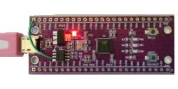
Lianshengde W806-KIT
As shown in the diagram, the jumper wires enable one-click serial port download, eliminating the need for manual reset.
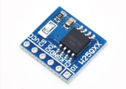
w25q32 module
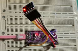
Refer to the board schematic for LED pin assignments:
VCC —> 3.3V
GND → GND
CS → PB4
CLK → PB2
DI → PB5
DO → PB3
4. Software Development
This experiment adds four files to the official SDK: spi.c, spi.h, w25qxx.c, and w25qxx.h
spi.c implements initialization of the SPI peripheral chip
1. //spi.c
2. #include "spi.h"
3.
4. SPI_HandleTypeDef hspi;
5.
6. void spi_init(void)
7. {
8. hspi.Instance = SPI;
9. hspi.Init.Mode = SPI_MODE_MASTER;
10. hspi.Init.CLKPolarity = SPI_POLARITY_LOW;
11. hspi.Init.CLKPhase = SPI_PHASE_1EDGE;
12. hspi.Init.NSS = SPI_NSS_SOFT;
13. hspi.Init.BaudRatePrescaler = SPI_BAUDRATEPRESCALER_20;
14. hspi.Init.FirstByte = SPI_LITTLEENDIAN;
15.
16. if (HAL_SPI_Init(&hspi) != HAL_OK)
17. {
18. while(1);
19. }
20. }
21.
22. void HAL_SPI_MspInit(SPI_HandleTypeDef *hspi)
23. {
24. __HAL_RCC_SPI_CLK_ENABLE();
25. __HAL_AFIO_REMAP_SPI_CS(GPIOB, GPIO_PIN_4);
26. __HAL_AFIO_REMAP_SPI_CLK(GPIOB, GPIO_PIN_2);
27. __HAL_AFIO_REMAP_SPI_MISO(GPIOB, GPIO_PIN_3);
28. __HAL_AFIO_REMAP_SPI_MOSI(GPIOB, GPIO_PIN_5);
29. }
30.
31. void HAL_SPI_MspDeInit(SPI_HandleTypeDef* hspi)
32. {
33. __HAL_RCC_SPI_CLK_DISABLE();
34. HAL_GPIO_DeInit(GPIOB, GPIO_PIN_2 | GPIO_PIN_3 | GPIO_PIN_4 | GPIO_PIN_5);
35. }
36.
37. uint8_t spi2_read_write_byte(uint8_t txdata)
38. {
39. uint8_t rxdata;
40.
41. HAL_SPI_TransmitReceive(&hspi, &txdata, &rxdata, 1, 1000);
42.
43. return rxdata;
44. }
spi.h contains function declarations, etc.
1. //spi.h
2. #ifndef _SPI_H
3. #define _SPI_H
4.
5. #include "stdint.h"
6. #include "wm_hal.h"
7.
8. extern SPI_HandleTypeDef hspi;
9.
10. void spi_init(void);
11. uint8_t spi2_read_write_byte(uint8_t txdata);
12.
13.
14. #endif
w25qxx.c implements flash read/write
1. //w25qxx.c
2. #include "w25qxx.h"
3. #include "wm_hal.h"
4. #include "spi.h"
5. #include "stdio.h"
6.
7. //For easy portability, implement the following functions
8. #define w25qxx_cs_high() __HAL_SPI_SET_CS_HIGH(&hspi);
9. #define w25qxx_cs_low() __HAL_SPI_SET_CS_LOW(&hspi);
10. #define w25qxx_r_w_byte(n) spi2_read_write_byte(n)
11. #define w25qxx_spi_init() spi_init()
12. #define w25qxx_delay_us(n) HAL_Delay(n)
13.
14.
15. w25qxx_device_t w25q32_dev = {
16. .init = w25qxx_init,
17. .wr = w25qxx_write,
18. .rd = w25qxx_read,
19. .type = 0x00,
20. };
21.
22.
23. void w25qxx_init(void)
24. {
25. w25qxx_spi_init(); // Initialize SPI
26. w25q32_dev.type = w25qxx_readid(); // Read FLASH ID.
27. }
28.
29.
30. // Read SPI_FLASH status register
31. //BIT7 6 5 4 3 2 1 0
32. //SPR RV TB BP2 BP1 BP0 WEL BUSY
33. //SPR: Default 0, status register protection bit, used with WP
34. //TB, BP2, BP1, BP0: Write protection settings for FLASH regions
35. //WEL: Write enable lock
36. //BUSY: Busy flag (1 = busy; 0 = idle)
37. //Default: 0x00
38. uint8_t w25qxx_readsr(void)
39. {
40. uint8_t byte = 0;
41. w25qxx_cs_low(); // Enable device
42. w25qxx_r_w_byte(W25X_ReadStatusReg); // Send command to read status register
43. byte = w25qxx_r_w_byte(0xff); // Read one byte
44. w25qxx_cs_high(); // Disable chip select
45. return byte;
46. }
47.
48.
49. // Write SPI_FLASH status register
50. // Only SPR, TB, BP2, BP1, BP0 (bits 7, 5, 4, 3, 2) are writable!!!
51. void w25qxx_write_sr(uint8_t sr)
52. {
53. w25qxx_cs_low(); // Enable device
54. w25qxx_r_w_byte(W25X_WriteStatusReg); // Send command to read/write status register
55. w25qxx_r_w_byte(sr); // Write one byte
56. w25qxx_cs_high(); // Disable chip select
57. }
58.
59.
60. // Enable SPI_FLASH write
61. // Set WEL bit
62. void w25qxx_write_enable(void)
63. {
64. w25qxx_cs_low(); // Enable device
65. w25qxx_r_w_byte(W25X_WriteEnable); //Send write enable
66. w25qxx_cs_high(); // Disable chip select
67. }
68.
69.
70. // Disable SPI_FLASH write
71. // Clear WEL
72. void w25qxx_write_disable(void)
73. {
74. w25qxx_cs_low(); // Enable device
75. w25qxx_r_w_byte(W25X_WriteDisable); // Send write disable command
76. w25qxx_cs_high(); // Disable chip select
77. }
78.
79.
80. // Read chip ID W25X16 ID: 0xEF15
81. uint16_t w25qxx_readid(void)
82. {
83. uint16_t temp = 0;
84. w25qxx_cs_low();
85.
86. w25qxx_r_w_byte(0x90); //Send read ID command
87. w25qxx_r_w_byte(0x00);
88. w25qxx_r_w_byte(0x00);
89. w25qxx_r_w_byte(0x00);
90. temp |= w25qxx_r_w_byte(0xFF) & << 8;
91. temp |= w25qxx_r_w_byte(0xFF);
92.
93. w25qxx_cs_high();
94.
95. return temp;
96. }
97.
98.
99. // Read SPI FLASH
100. // Read specified length of data starting at specified address
101. //pbuffer: Data storage area
102. //read_addr: Start address for reading (24-bit)
103. //num_byte_to_read: Number of bytes to read (max 65535)
104. void w25qxx_read(uint8_t* pbuffer, uint32_t read_addr, uint16_t num_byte_to_read)
105. {
106. uint16_t i;
107.
108. w25qxx_cs_low();
109. w25qxx_r_w_byte(W25X_ReadData); //Send read command
110. w25qxx_r_w_byte((uint8_t)((read_addr) >> 16)); // Send 24-bit address
111. w25qxx_r_w_byte((uint8_t)((read_addr) >> 8));
112. w25qxx_r_w_byte((uint8_t)read_addr);
113. for(i = 0; i < num_byte_to_read; i++)
114. {
115. pbuffer = w25qxx_r_w_byte(0xFF); // Read data in a loop
116. }
117. w25qxx_cs_high();
118. }
119.
120.
121. // SPI writes less than 256 bytes of data within one page (0~65535)
122. //Writes up to 256 bytes starting at a specified address
123. //pbuffer: Data storage area
124. //write_addr: Starting address for writing (24-bit)
125. //num_byte_to_write: Number of bytes to write (max 256). This value must not exceed the remaining bytes in the page!!!
126. void w25qxx_write_page(uint8_t* pbuffer, uint32_t write_addr, uint16_t num_byte_to_write)
127. {
128. uint16_t i;
129.
130. w25qxx_write_enable(); //SET WEL
131. w25qxx_cs_low();
132. w25qxx_r_w_byte(W25X_PageProgram); //Send write page command
133. w25qxx_r_w_byte((uint8_t)((write_addr) >> 16)); // Send 24-bit address
134. w25qxx_r_w_byte((uint8_t)((write_addr) >> 8));
135. w25qxx_r_w_byte((uint8_t)write_addr);
136. for(i = 0; i < num_byte_to_write; i++)
137. w25qxx_r_w_byte(pbuffer[i]); // Write data in a loop
138. w25qxx_cs_high();
139.
140. w25qxx_wait_busy(); //Wait for write operation to complete
141. }
142.
143.
144. // Unverified write to SPI FLASH
145. // Must ensure all data within the written address range is 0xFF; otherwise, writing data to non-0xFF locations will fail!
146. // Features automatic page switching
147. //Writes specified-length data starting at the designated address, but must ensure the address does not exceed bounds!
148. //pbuffer: Data storage area
149. //write_addr: Starting write address (24-bit)
150. //num_byte_to_write: Number of bytes to write (maximum 65535)
151. //CHECK OK
152. void w25qxx_write_nocheck(uint8_t* pbuffer, uint32_t write_addr, uint16_t num_byte_to_write)
153. {
154. uint16_t pageremain;
155.
156. pageremain = 256 - write_addr % 256; // Remaining bytes per page
157. if(num_byte_to_write <= pageremain)
158. pageremain = num_byte_to_write; // Not exceeding 256 bytes
159. while(1)
160. {
161. w25qxx_write_page(pbuffer, write_addr, pageremain);
162. if(num_byte_to_write == pageremain) // Writing completed
163. break;
164. else //num_byte_to_write > pageremain
165. {
166. pbuffer += pageremain;
167. write_addr += pageremain;
168.
169. num_byte_to_write -= pageremain; // Subtract the number of bytes already written
170. if(num_byte_to_write > 256)
171. pageremain = 256; // Can write 256 bytes at a time
172. else
173. pageremain = num_byte_to_write; // Less than 256 bytes
174. }
175. };
176. }
177.
178.
179. // Write to SPI FLASH
180. //Begin writing specified length of data at designated address
181. //This function includes an erase operation!
182. //pbuffer: Data storage area
183. //write_addr: Start address for writing (24-bit)
184. //num_byte_to_write: Number of bytes to write (max 65535)
185. uint8_t W25QXX_BUFFER[4096];
186. void w25qxx_write(uint8_t* pbuffer, uint32_t write_addr, uint16_t num_byte_to_write)
187. {
188. uint32_t secpos;
189. uint16_t secoff;
190. uint16_t secremain;
191. uint16_t i;
192.
193. secpos = write_addr / 4096; // Sector address 0~511 for w25x16
194. secoff = write_addr % 4096; // Offset within the sector
195. secremain = 4096 - secoff; // Remaining space in sector
196.
197. if(num_byte_to_write <= secremain)
198. secremain = num_byte_to_write; // Not exceeding 4096 bytes
199. while(1)
200. {
201. w25qxx_read(W25QXX_BUFFER, secpos * 4096, 4096); // Read entire sector contents
202. for(i = 0; i < secremain; i++) // Verify data
203. {
204. if(W25QXX_BUFFER[secoff+i] != 0xFF)
205. break; // Requires erasure
206. }
207. if(i < secremain) // Requires erasure
208. {
209. w25qxx_erase_sector(secpos); // Erase this sector
210. for(i = 0; i < secremain; i++) // Copy
211. {
212. W25QXX_BUFFER[i + secoff] = pbuffer[i];
213. }
214. w25qxx_write_nocheck(W25QXX_BUFFER, secpos * 4096, 4096); // Write entire sector
215.
216. }else
217. w25qxx_write_nocheck(pbuffer, write_addr, secremain); // Write to the remaining sector space after erasure.
218. if(num_byte_to_write == secremain)
219. break; // Writing completed
220. else // Writing not finished
221. {
222. secpos++; // Increment sector address by 1
223. secoff = 0; // Set offset to 0
224.
225. pbuffer += secremain; // Increment pointer offset
226. write_addr += secremain; // Write address offset
227. num_byte_to_write -= secremain; // Decrement byte count
228. if(num_byte_to_write > 4096)
229. secremain = 4096; // Next sector still insufficient
230. else secremain = num_byte_to_write; // Next sector can be written completely
231. }
232. };
233. }
234.
235.
236. // Erase entire chip
237. // Total erase time:
238. //W25X16: 25s
239. //W25X32: 40s
240. //W25X64: 40s
241. //Extremely long wait time...
242. void W25QXX_Erase_Chip(void)
243. {
244. w25qxx_write_enable(); //SET WEL
245. w25qxx_wait_busy();
246. w25qxx_cs_low(); // Enable device
247. w25qxx_r_w_byte(W25X_ChipErase); // Send chip erase command
248. w25qxx_cs_high(); // Clear chip select
249. w25qxx_wait_busy(); // Wait for chip erase to complete
250. }
251.
252.
253. // Erase a sector
254. //dst_addr: Sector address 0~511 for w25x16
255. //Minimum time to erase one sector: 150ms
256. void w25qxx_erase_sector(uint32_t dst_addr)
257. {
258. dst_addr *= 4096;
259. w25qxx_write_enable(); //SET WEL
260. w25qxx_wait_busy();
261. w25qxx_cs_low(); // Enable device
262. w25qxx_r_w_byte(W25X_SectorErase); //Send sector erase command
263. w25qxx_r_w_byte((uint8_t)((dst_addr) >> 16)); // Send 24-bit address
264. w25qxx_r_w_byte((uint8_t)((dst_addr) >> 8));
265. w25qxx_r_w_byte((uint8_t)dst_addr);
266. w25qxx_cs_high(); // Clear chip select
267. w25qxx_wait_busy(); //Wait for erase completion
268. }
269.
270.
271. // Wait for idle
272. void w25qxx_wait_busy(void)
273. {
274. while((w25qxx_readsr() & 0x01) == 0x01); // Wait for BUSY bit to clear
275. }
276.
277.
278. // Enter power-down mode
279. void W25QXX_PowerDown(void)
280. {
281. w25qxx_cs_low(); // Enable device
282. w25qxx_r_w_byte(W25X_PowerDown); // Send power-down command
283. w25qxx_cs_high(); // Disable chip select
284. w25qxx_delay_us(3); // Wait for TPD
285. }
286.
287.
288. // Wake up
289. void W25QXX_WAKEUP(void)
290. {
291. w25qxx_cs_low(); // Enable device
292. w25qxx_r_w_byte(W25X_ReleasePowerDown); //send W25X_PowerDown command 0xAB
293. w25qxx_cs_high(); // Disable chip select
294. w25qxx_delay_us(3); // Wait for TRES1
295. }
w25qxx.h
1. #ifndef _W25QXX_H
2. #define _W25QXX_H
3.
4. #include "stdint.h"
5.
6. //W25X Series/Q Series Chip List
7. #define W25Q80 0XEF13
8. #define W25Q16 0xEF14
9. #define W25Q32 0xEF15
10. #define W25Q64 0xEF16
11. #define W25Q128 0XEF17
12.
13. //W25X16 read/write
14. //#define FLASH_ID 0XEF14
15. // Instruction Table
16. #define W25X_WriteEnable 0x06
17. #define W25X_WriteDisable 0x04
18. #define W25X_ReadStatusReg 0x05
19. #define W25X_WriteStatusReg 0x01
20. #define W25X_ReadData 0x03
21. #define W25X_FastReadData 0x0B
22. #define W25X_FastReadDual 0x3B
23. #define W25X_PageProgram 0x02
24. #define W25X_BlockErase 0xD8
25. #define W25X_SectorErase 0x20
26. #define W25X_ChipErase 0xC7
27. #define W25X_PowerDown 0xB9
28. #define W25X_ReleasePowerDown 0xAB
29. #define W25X_DeviceID 0xAB
30. #define W25X_ManufactDeviceID 0x90
31. #define W25X_JedecDeviceID 0x9F
32.
33. typedef struct w25qxx_device_s{
34. void (*init) (void);
35. void (*wr) (uint8_t* pbuffer, uint32_t read_addr, uint16_t num_byte_to_read);
36. void (*rd) (uint8_t* pbuffer, uint32_t write_addr, uint16_t num_byte_to_write);
37. uint16_t type;
38. }w25qxx_device_t;
39.
40. extern w25qxx_device_t w25q32_dev;
41.
42. void w25qxx_init(void);
43. uint16_t w25qxx_readid(void);
44. uint8_t w25qxx_readsr(void); // Read status register
45. void w25qxx_write_sr(uint8_t sr); // Write status register
46. void w25qxx_write_enable(void); // Write enable
47. void w25qxx_write_disable(void); // Write protection
48. void w25qxx_read(uint8_t* pbuffer, uint32_t read_addr, uint16_t num_byte_to_read); // Read flash
49. void w25qxx_write(uint8_t* pbuffer, uint32_t write_addr, uint16_t num_byte_to_write); // Write to flash
50. void w25qxx_erase_chip(void); // Erase entire chip
51. void w25qxx_erase_sector(uint32_t dst_addr); // Erase sector
52. void w25qxx_wait_busy(void); //Wait for idle
53. void w25qxx_powerdown(void); // Enter power-down mode
54. void w25qxx_wakeup(void); // Wake up
55.
56.
57. #endif
Modify main.c
1. #include <stdio.h>
2.#include "wm_hal.h"
3. #include "led.h"
4. //#include "csi_config.h"
5. #include "w25qxx.h"
6.
7. void Error_Handler(void);
8. void led_init(void);
9.
10. uint16_t rd_date[2048] = {0};
11. uint16_t wr_date[2048] = {0};
12.
13. int main(void)
14. {
15. uint16_t i = 0;
16.
17. SystemClock_Config(CPU_CLK_160M);
18. printf("enter main\r\n");
19. printf("hello,world\r\n");
20.
21. led_init();
22. w25q32_dev.init();
23.
24. if(w25q32_dev.type != W25Q32)
25. {
26. printf("W25Q32 flash initialization error!\r\n");
27. } else {
28. printf("w25q32 flash initialization successful!\r\n");
29. }
30.
31. printf("writing flash data (0~4095): \r\n");
32. for(i = 0; i < 2048; i++)
33. {
34. wr_date[i] = i;
35. }
36. w25q32_dev.wr((uint8_t *)wr_date, 0, 4096);
37.
38. w25q32_dev.rd((uint8_t *)rd_date, 0, 4096);
39.
40. printf("read flash data: \r\n");
41. for(i = 0; i < 2048; i++)
42. {
43. printf("%d, ", rd_date[i]);
44. }
45. printf("\r\n");
46.
47. while (1)
48. {
49. printf(".");
50. HAL_Delay(500);
51. }
52. }
53.
54.
55.
56. void Error_Handler(void)
57. {
58. while (1)
59. {
60. }
61. }
62.
63. void assert_failed(uint8_t *file, uint32_t line)
64. {
65. printf("Invalid parameter values: file %s on line %d\r\n", file, line);
66. }
5. Compile and Download the Program
Right-click the project → Select Build
The project compilation output is as follows. No errors or warnings indicate successful compilation.
<img src=".\pic\02_build.png" style="zoom:80%;" align="left">
Launch Upgrade_Tools_V1.4.8.exe to begin downloading the program
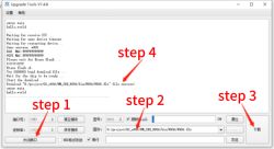
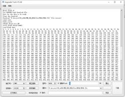
6. Experimental Results
Data write and read operations succeeded!
7. Summary
Here, SPI-related code and W25Q32 code are separated into distinct layers, facilitating porting of the W25Q32 to other platforms.
SPI read/write operations at other speeds were tested and functioned normally.[/i][/i][/i][/i]
Program Development Platform: CDK
Program Download Software: Upgrade_Tools_V1.4.8.exe
Drivers: CH340 USB-to-Serial Driver
For related development platform setup and installation, refer to online tutorials. In hardware development scenarios, the development environment often needs to adapt to different peripheral interaction requirements. For instance, some complex projects may simultaneously involve memory chips (such as the w25q32 in this article), display interfaces (e.g., DVI vs HDMI), and timing control modules (e.g., monostable multivibrator). The choice between DVI and HDMI depends on display requirements: For projects requiring only digital video signal transmission (e.g., monochrome display panels in industrial equipment), the DVI interface meets basic needs. For synchronous audio-video transmission (e.g., smart devices with interactive interfaces), the HDMI interface (especially versions 2.0 and above supporting 4K@60Hz) is more suitable. The monostable multivibrator can be utilized for timing calibration. For instance, in SPI communication between the W25Q32 and the host controller, if signal jitter causes data transmission errors, the multivibrator can generate fixed-width trigger pulses to stabilize the SPI clock (CLK) or chip select (CS) signal. This ensures accurate execution of read/write commands — — This module becomes particularly crucial during subsequent complex hardware expansions (e.g., adding display interfaces or sensors), necessitating the pre-reservation of timing debug interfaces within the development environment.
2. Experiment Objective
Write values from 0 to 4095 to the first sector of the W25Q32, then read and print the data.
3. Hardware Platform
Lianshengde W806-KIT
As shown in the diagram, the jumper wires enable one-click serial port download, eliminating the need for manual reset.

w25q32 module

Refer to the board schematic for LED pin assignments:
VCC —> 3.3V
GND → GND
CS → PB4
CLK → PB2
DI → PB5
DO → PB3

4. Software Development
This experiment adds four files to the official SDK: spi.c, spi.h, w25qxx.c, and w25qxx.h
spi.c implements initialization of the SPI peripheral chip
1. //spi.c
2. #include "spi.h"
3.
4. SPI_HandleTypeDef hspi;
5.
6. void spi_init(void)
7. {
8. hspi.Instance = SPI;
9. hspi.Init.Mode = SPI_MODE_MASTER;
10. hspi.Init.CLKPolarity = SPI_POLARITY_LOW;
11. hspi.Init.CLKPhase = SPI_PHASE_1EDGE;
12. hspi.Init.NSS = SPI_NSS_SOFT;
13. hspi.Init.BaudRatePrescaler = SPI_BAUDRATEPRESCALER_20;
14. hspi.Init.FirstByte = SPI_LITTLEENDIAN;
15.
16. if (HAL_SPI_Init(&hspi) != HAL_OK)
17. {
18. while(1);
19. }
20. }
21.
22. void HAL_SPI_MspInit(SPI_HandleTypeDef *hspi)
23. {
24. __HAL_RCC_SPI_CLK_ENABLE();
25. __HAL_AFIO_REMAP_SPI_CS(GPIOB, GPIO_PIN_4);
26. __HAL_AFIO_REMAP_SPI_CLK(GPIOB, GPIO_PIN_2);
27. __HAL_AFIO_REMAP_SPI_MISO(GPIOB, GPIO_PIN_3);
28. __HAL_AFIO_REMAP_SPI_MOSI(GPIOB, GPIO_PIN_5);
29. }
30.
31. void HAL_SPI_MspDeInit(SPI_HandleTypeDef* hspi)
32. {
33. __HAL_RCC_SPI_CLK_DISABLE();
34. HAL_GPIO_DeInit(GPIOB, GPIO_PIN_2 | GPIO_PIN_3 | GPIO_PIN_4 | GPIO_PIN_5);
35. }
36.
37. uint8_t spi2_read_write_byte(uint8_t txdata)
38. {
39. uint8_t rxdata;
40.
41. HAL_SPI_TransmitReceive(&hspi, &txdata, &rxdata, 1, 1000);
42.
43. return rxdata;
44. }
spi.h contains function declarations, etc.
1. //spi.h
2. #ifndef _SPI_H
3. #define _SPI_H
4.
5. #include "stdint.h"
6. #include "wm_hal.h"
7.
8. extern SPI_HandleTypeDef hspi;
9.
10. void spi_init(void);
11. uint8_t spi2_read_write_byte(uint8_t txdata);
12.
13.
14. #endif
w25qxx.c implements flash read/write
1. //w25qxx.c
2. #include "w25qxx.h"
3. #include "wm_hal.h"
4. #include "spi.h"
5. #include "stdio.h"
6.
7. //For easy portability, implement the following functions
8. #define w25qxx_cs_high() __HAL_SPI_SET_CS_HIGH(&hspi);
9. #define w25qxx_cs_low() __HAL_SPI_SET_CS_LOW(&hspi);
10. #define w25qxx_r_w_byte(n) spi2_read_write_byte(n)
11. #define w25qxx_spi_init() spi_init()
12. #define w25qxx_delay_us(n) HAL_Delay(n)
13.
14.
15. w25qxx_device_t w25q32_dev = {
16. .init = w25qxx_init,
17. .wr = w25qxx_write,
18. .rd = w25qxx_read,
19. .type = 0x00,
20. };
21.
22.
23. void w25qxx_init(void)
24. {
25. w25qxx_spi_init(); // Initialize SPI
26. w25q32_dev.type = w25qxx_readid(); // Read FLASH ID.
27. }
28.
29.
30. // Read SPI_FLASH status register
31. //BIT7 6 5 4 3 2 1 0
32. //SPR RV TB BP2 BP1 BP0 WEL BUSY
33. //SPR: Default 0, status register protection bit, used with WP
34. //TB, BP2, BP1, BP0: Write protection settings for FLASH regions
35. //WEL: Write enable lock
36. //BUSY: Busy flag (1 = busy; 0 = idle)
37. //Default: 0x00
38. uint8_t w25qxx_readsr(void)
39. {
40. uint8_t byte = 0;
41. w25qxx_cs_low(); // Enable device
42. w25qxx_r_w_byte(W25X_ReadStatusReg); // Send command to read status register
43. byte = w25qxx_r_w_byte(0xff); // Read one byte
44. w25qxx_cs_high(); // Disable chip select
45. return byte;
46. }
47.
48.
49. // Write SPI_FLASH status register
50. // Only SPR, TB, BP2, BP1, BP0 (bits 7, 5, 4, 3, 2) are writable!!!
51. void w25qxx_write_sr(uint8_t sr)
52. {
53. w25qxx_cs_low(); // Enable device
54. w25qxx_r_w_byte(W25X_WriteStatusReg); // Send command to read/write status register
55. w25qxx_r_w_byte(sr); // Write one byte
56. w25qxx_cs_high(); // Disable chip select
57. }
58.
59.
60. // Enable SPI_FLASH write
61. // Set WEL bit
62. void w25qxx_write_enable(void)
63. {
64. w25qxx_cs_low(); // Enable device
65. w25qxx_r_w_byte(W25X_WriteEnable); //Send write enable
66. w25qxx_cs_high(); // Disable chip select
67. }
68.
69.
70. // Disable SPI_FLASH write
71. // Clear WEL
72. void w25qxx_write_disable(void)
73. {
74. w25qxx_cs_low(); // Enable device
75. w25qxx_r_w_byte(W25X_WriteDisable); // Send write disable command
76. w25qxx_cs_high(); // Disable chip select
77. }
78.
79.
80. // Read chip ID W25X16 ID: 0xEF15
81. uint16_t w25qxx_readid(void)
82. {
83. uint16_t temp = 0;
84. w25qxx_cs_low();
85.
86. w25qxx_r_w_byte(0x90); //Send read ID command
87. w25qxx_r_w_byte(0x00);
88. w25qxx_r_w_byte(0x00);
89. w25qxx_r_w_byte(0x00);
90. temp |= w25qxx_r_w_byte(0xFF) & << 8;
91. temp |= w25qxx_r_w_byte(0xFF);
92.
93. w25qxx_cs_high();
94.
95. return temp;
96. }
97.
98.
99. // Read SPI FLASH
100. // Read specified length of data starting at specified address
101. //pbuffer: Data storage area
102. //read_addr: Start address for reading (24-bit)
103. //num_byte_to_read: Number of bytes to read (max 65535)
104. void w25qxx_read(uint8_t* pbuffer, uint32_t read_addr, uint16_t num_byte_to_read)
105. {
106. uint16_t i;
107.
108. w25qxx_cs_low();
109. w25qxx_r_w_byte(W25X_ReadData); //Send read command
110. w25qxx_r_w_byte((uint8_t)((read_addr) >> 16)); // Send 24-bit address
111. w25qxx_r_w_byte((uint8_t)((read_addr) >> 8));
112. w25qxx_r_w_byte((uint8_t)read_addr);
113. for(i = 0; i < num_byte_to_read; i++)
114. {
115. pbuffer = w25qxx_r_w_byte(0xFF); // Read data in a loop
116. }
117. w25qxx_cs_high();
118. }
119.
120.
121. // SPI writes less than 256 bytes of data within one page (0~65535)
122. //Writes up to 256 bytes starting at a specified address
123. //pbuffer: Data storage area
124. //write_addr: Starting address for writing (24-bit)
125. //num_byte_to_write: Number of bytes to write (max 256). This value must not exceed the remaining bytes in the page!!!
126. void w25qxx_write_page(uint8_t* pbuffer, uint32_t write_addr, uint16_t num_byte_to_write)
127. {
128. uint16_t i;
129.
130. w25qxx_write_enable(); //SET WEL
131. w25qxx_cs_low();
132. w25qxx_r_w_byte(W25X_PageProgram); //Send write page command
133. w25qxx_r_w_byte((uint8_t)((write_addr) >> 16)); // Send 24-bit address
134. w25qxx_r_w_byte((uint8_t)((write_addr) >> 8));
135. w25qxx_r_w_byte((uint8_t)write_addr);
136. for(i = 0; i < num_byte_to_write; i++)
137. w25qxx_r_w_byte(pbuffer[i]); // Write data in a loop
138. w25qxx_cs_high();
139.
140. w25qxx_wait_busy(); //Wait for write operation to complete
141. }
142.
143.
144. // Unverified write to SPI FLASH
145. // Must ensure all data within the written address range is 0xFF; otherwise, writing data to non-0xFF locations will fail!
146. // Features automatic page switching
147. //Writes specified-length data starting at the designated address, but must ensure the address does not exceed bounds!
148. //pbuffer: Data storage area
149. //write_addr: Starting write address (24-bit)
150. //num_byte_to_write: Number of bytes to write (maximum 65535)
151. //CHECK OK
152. void w25qxx_write_nocheck(uint8_t* pbuffer, uint32_t write_addr, uint16_t num_byte_to_write)
153. {
154. uint16_t pageremain;
155.
156. pageremain = 256 - write_addr % 256; // Remaining bytes per page
157. if(num_byte_to_write <= pageremain)
158. pageremain = num_byte_to_write; // Not exceeding 256 bytes
159. while(1)
160. {
161. w25qxx_write_page(pbuffer, write_addr, pageremain);
162. if(num_byte_to_write == pageremain) // Writing completed
163. break;
164. else //num_byte_to_write > pageremain
165. {
166. pbuffer += pageremain;
167. write_addr += pageremain;
168.
169. num_byte_to_write -= pageremain; // Subtract the number of bytes already written
170. if(num_byte_to_write > 256)
171. pageremain = 256; // Can write 256 bytes at a time
172. else
173. pageremain = num_byte_to_write; // Less than 256 bytes
174. }
175. };
176. }
177.
178.
179. // Write to SPI FLASH
180. //Begin writing specified length of data at designated address
181. //This function includes an erase operation!
182. //pbuffer: Data storage area
183. //write_addr: Start address for writing (24-bit)
184. //num_byte_to_write: Number of bytes to write (max 65535)
185. uint8_t W25QXX_BUFFER[4096];
186. void w25qxx_write(uint8_t* pbuffer, uint32_t write_addr, uint16_t num_byte_to_write)
187. {
188. uint32_t secpos;
189. uint16_t secoff;
190. uint16_t secremain;
191. uint16_t i;
192.
193. secpos = write_addr / 4096; // Sector address 0~511 for w25x16
194. secoff = write_addr % 4096; // Offset within the sector
195. secremain = 4096 - secoff; // Remaining space in sector
196.
197. if(num_byte_to_write <= secremain)
198. secremain = num_byte_to_write; // Not exceeding 4096 bytes
199. while(1)
200. {
201. w25qxx_read(W25QXX_BUFFER, secpos * 4096, 4096); // Read entire sector contents
202. for(i = 0; i < secremain; i++) // Verify data
203. {
204. if(W25QXX_BUFFER[secoff+i] != 0xFF)
205. break; // Requires erasure
206. }
207. if(i < secremain) // Requires erasure
208. {
209. w25qxx_erase_sector(secpos); // Erase this sector
210. for(i = 0; i < secremain; i++) // Copy
211. {
212. W25QXX_BUFFER[i + secoff] = pbuffer[i];
213. }
214. w25qxx_write_nocheck(W25QXX_BUFFER, secpos * 4096, 4096); // Write entire sector
215.
216. }else
217. w25qxx_write_nocheck(pbuffer, write_addr, secremain); // Write to the remaining sector space after erasure.
218. if(num_byte_to_write == secremain)
219. break; // Writing completed
220. else // Writing not finished
221. {
222. secpos++; // Increment sector address by 1
223. secoff = 0; // Set offset to 0
224.
225. pbuffer += secremain; // Increment pointer offset
226. write_addr += secremain; // Write address offset
227. num_byte_to_write -= secremain; // Decrement byte count
228. if(num_byte_to_write > 4096)
229. secremain = 4096; // Next sector still insufficient
230. else secremain = num_byte_to_write; // Next sector can be written completely
231. }
232. };
233. }
234.
235.
236. // Erase entire chip
237. // Total erase time:
238. //W25X16: 25s
239. //W25X32: 40s
240. //W25X64: 40s
241. //Extremely long wait time...
242. void W25QXX_Erase_Chip(void)
243. {
244. w25qxx_write_enable(); //SET WEL
245. w25qxx_wait_busy();
246. w25qxx_cs_low(); // Enable device
247. w25qxx_r_w_byte(W25X_ChipErase); // Send chip erase command
248. w25qxx_cs_high(); // Clear chip select
249. w25qxx_wait_busy(); // Wait for chip erase to complete
250. }
251.
252.
253. // Erase a sector
254. //dst_addr: Sector address 0~511 for w25x16
255. //Minimum time to erase one sector: 150ms
256. void w25qxx_erase_sector(uint32_t dst_addr)
257. {
258. dst_addr *= 4096;
259. w25qxx_write_enable(); //SET WEL
260. w25qxx_wait_busy();
261. w25qxx_cs_low(); // Enable device
262. w25qxx_r_w_byte(W25X_SectorErase); //Send sector erase command
263. w25qxx_r_w_byte((uint8_t)((dst_addr) >> 16)); // Send 24-bit address
264. w25qxx_r_w_byte((uint8_t)((dst_addr) >> 8));
265. w25qxx_r_w_byte((uint8_t)dst_addr);
266. w25qxx_cs_high(); // Clear chip select
267. w25qxx_wait_busy(); //Wait for erase completion
268. }
269.
270.
271. // Wait for idle
272. void w25qxx_wait_busy(void)
273. {
274. while((w25qxx_readsr() & 0x01) == 0x01); // Wait for BUSY bit to clear
275. }
276.
277.
278. // Enter power-down mode
279. void W25QXX_PowerDown(void)
280. {
281. w25qxx_cs_low(); // Enable device
282. w25qxx_r_w_byte(W25X_PowerDown); // Send power-down command
283. w25qxx_cs_high(); // Disable chip select
284. w25qxx_delay_us(3); // Wait for TPD
285. }
286.
287.
288. // Wake up
289. void W25QXX_WAKEUP(void)
290. {
291. w25qxx_cs_low(); // Enable device
292. w25qxx_r_w_byte(W25X_ReleasePowerDown); //send W25X_PowerDown command 0xAB
293. w25qxx_cs_high(); // Disable chip select
294. w25qxx_delay_us(3); // Wait for TRES1
295. }
w25qxx.h
1. #ifndef _W25QXX_H
2. #define _W25QXX_H
3.
4. #include "stdint.h"
5.
6. //W25X Series/Q Series Chip List
7. #define W25Q80 0XEF13
8. #define W25Q16 0xEF14
9. #define W25Q32 0xEF15
10. #define W25Q64 0xEF16
11. #define W25Q128 0XEF17
12.
13. //W25X16 read/write
14. //#define FLASH_ID 0XEF14
15. // Instruction Table
16. #define W25X_WriteEnable 0x06
17. #define W25X_WriteDisable 0x04
18. #define W25X_ReadStatusReg 0x05
19. #define W25X_WriteStatusReg 0x01
20. #define W25X_ReadData 0x03
21. #define W25X_FastReadData 0x0B
22. #define W25X_FastReadDual 0x3B
23. #define W25X_PageProgram 0x02
24. #define W25X_BlockErase 0xD8
25. #define W25X_SectorErase 0x20
26. #define W25X_ChipErase 0xC7
27. #define W25X_PowerDown 0xB9
28. #define W25X_ReleasePowerDown 0xAB
29. #define W25X_DeviceID 0xAB
30. #define W25X_ManufactDeviceID 0x90
31. #define W25X_JedecDeviceID 0x9F
32.
33. typedef struct w25qxx_device_s{
34. void (*init) (void);
35. void (*wr) (uint8_t* pbuffer, uint32_t read_addr, uint16_t num_byte_to_read);
36. void (*rd) (uint8_t* pbuffer, uint32_t write_addr, uint16_t num_byte_to_write);
37. uint16_t type;
38. }w25qxx_device_t;
39.
40. extern w25qxx_device_t w25q32_dev;
41.
42. void w25qxx_init(void);
43. uint16_t w25qxx_readid(void);
44. uint8_t w25qxx_readsr(void); // Read status register
45. void w25qxx_write_sr(uint8_t sr); // Write status register
46. void w25qxx_write_enable(void); // Write enable
47. void w25qxx_write_disable(void); // Write protection
48. void w25qxx_read(uint8_t* pbuffer, uint32_t read_addr, uint16_t num_byte_to_read); // Read flash
49. void w25qxx_write(uint8_t* pbuffer, uint32_t write_addr, uint16_t num_byte_to_write); // Write to flash
50. void w25qxx_erase_chip(void); // Erase entire chip
51. void w25qxx_erase_sector(uint32_t dst_addr); // Erase sector
52. void w25qxx_wait_busy(void); //Wait for idle
53. void w25qxx_powerdown(void); // Enter power-down mode
54. void w25qxx_wakeup(void); // Wake up
55.
56.
57. #endif
Modify main.c
1. #include <stdio.h>
2.#include "wm_hal.h"
3. #include "led.h"
4. //#include "csi_config.h"
5. #include "w25qxx.h"
6.
7. void Error_Handler(void);
8. void led_init(void);
9.
10. uint16_t rd_date[2048] = {0};
11. uint16_t wr_date[2048] = {0};
12.
13. int main(void)
14. {
15. uint16_t i = 0;
16.
17. SystemClock_Config(CPU_CLK_160M);
18. printf("enter main\r\n");
19. printf("hello,world\r\n");
20.
21. led_init();
22. w25q32_dev.init();
23.
24. if(w25q32_dev.type != W25Q32)
25. {
26. printf("W25Q32 flash initialization error!\r\n");
27. } else {
28. printf("w25q32 flash initialization successful!\r\n");
29. }
30.
31. printf("writing flash data (0~4095): \r\n");
32. for(i = 0; i < 2048; i++)
33. {
34. wr_date[i] = i;
35. }
36. w25q32_dev.wr((uint8_t *)wr_date, 0, 4096);
37.
38. w25q32_dev.rd((uint8_t *)rd_date, 0, 4096);
39.
40. printf("read flash data: \r\n");
41. for(i = 0; i < 2048; i++)
42. {
43. printf("%d, ", rd_date[i]);
44. }
45. printf("\r\n");
46.
47. while (1)
48. {
49. printf(".");
50. HAL_Delay(500);
51. }
52. }
53.
54.
55.
56. void Error_Handler(void)
57. {
58. while (1)
59. {
60. }
61. }
62.
63. void assert_failed(uint8_t *file, uint32_t line)
64. {
65. printf("Invalid parameter values: file %s on line %d\r\n", file, line);
66. }
5. Compile and Download the Program
Right-click the project → Select Build
The project compilation output is as follows. No errors or warnings indicate successful compilation.
<img src=".\pic\02_build.png" style="zoom:80%;" align="left">
Launch Upgrade_Tools_V1.4.8.exe to begin downloading the program

6. Experimental Results
Data write and read operations succeeded!

7. Summary
Here, SPI-related code and W25Q32 code are separated into distinct layers, facilitating porting of the W25Q32 to other platforms.
SPI read/write operations at other speeds were tested and functioned normally.[/i][/i][/i][/i]


