Hi everyone,
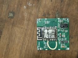
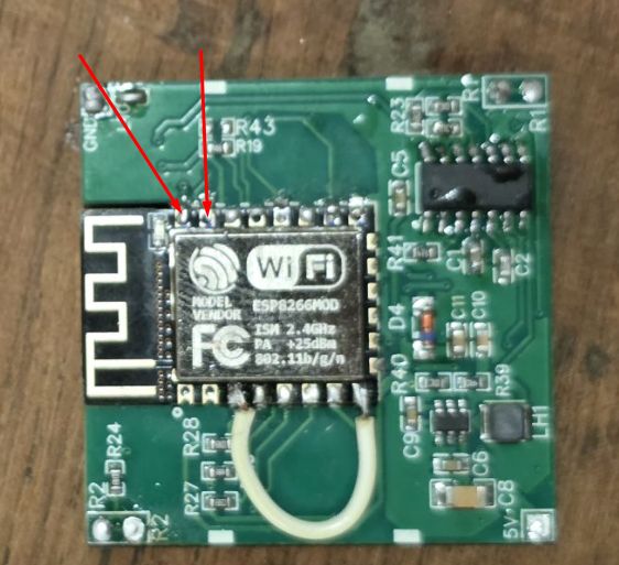
I’m working on a homemade / modified 4-channel relay board. Originally the board used a Tuya CB3S (BK7231) Wi-Fi module. I removed the CB3S and replaced it with an ESP8266 module (ESP-12F / ESP86322) so I can run ESPHome.
The ESP8266 is working perfectly:
It boots correctly.
Connects to Wi-Fi.
Shows up in ESPHome.
Web UI works.
Status LED (GPIO2) works.
OTA updates work.
But the relay outputs do not switch, no matter which GPIO I assign in ESPHome.
What I already tested:
5 V rail is present (about 4.8 V), regulator outputs 3.3 V correctly.
ESP8266 VCC, EN, GND, GPIO0, GPIO2, and GPIO15 are all wired properly.
ESPHome firmware is running.
Web server control panel loads.
I tested GPIO4, GPIO5, GPIO12, GPIO13, and GPIO14 as outputs.
None of them activate the relay/triac drivers on this board.
Touch buttons also don’t trigger any change in the GPIO inputs.
My suspicion:
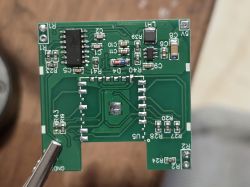
The original relay driver traces may not be connected to the pins I assumed, or I may have missed a trace that was originally routed under the CB3S module.
What I need help with:
How to correctly trace which GPIO goes to each relay driver (there are 4 channels)?
Whether the CB3S had internal copper bridges that the ESP8266 does not recreate?
Any known pin mappings for 4-gang Tuya touch/relay boards?
Advice on identifying the relay control lines (R5 / R7 / Q1 / Q2 etc.)?
Confirming whether I need to restore any missing jumpers / traces under the CB3S footprint?
If needed, I can provide clear PCB photos (front, back, and close-ups of the relay driver section and CB3S footprint).
Any help would be greatly appreciated — I’ve got ESPHome fully running but cannot get the relay outputs to toggle.
Thank you!


