logo elektroda
logo elektroda
X
logo elektroda

WB03A Chip Pinout and Identification for 3Gang Smart Switch Soldering

rufus33 624 14
ADVERTISEMENT
  • #1 21836503
    rufus33
    Level 4  
    Posts: 9
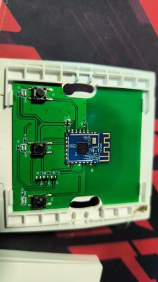
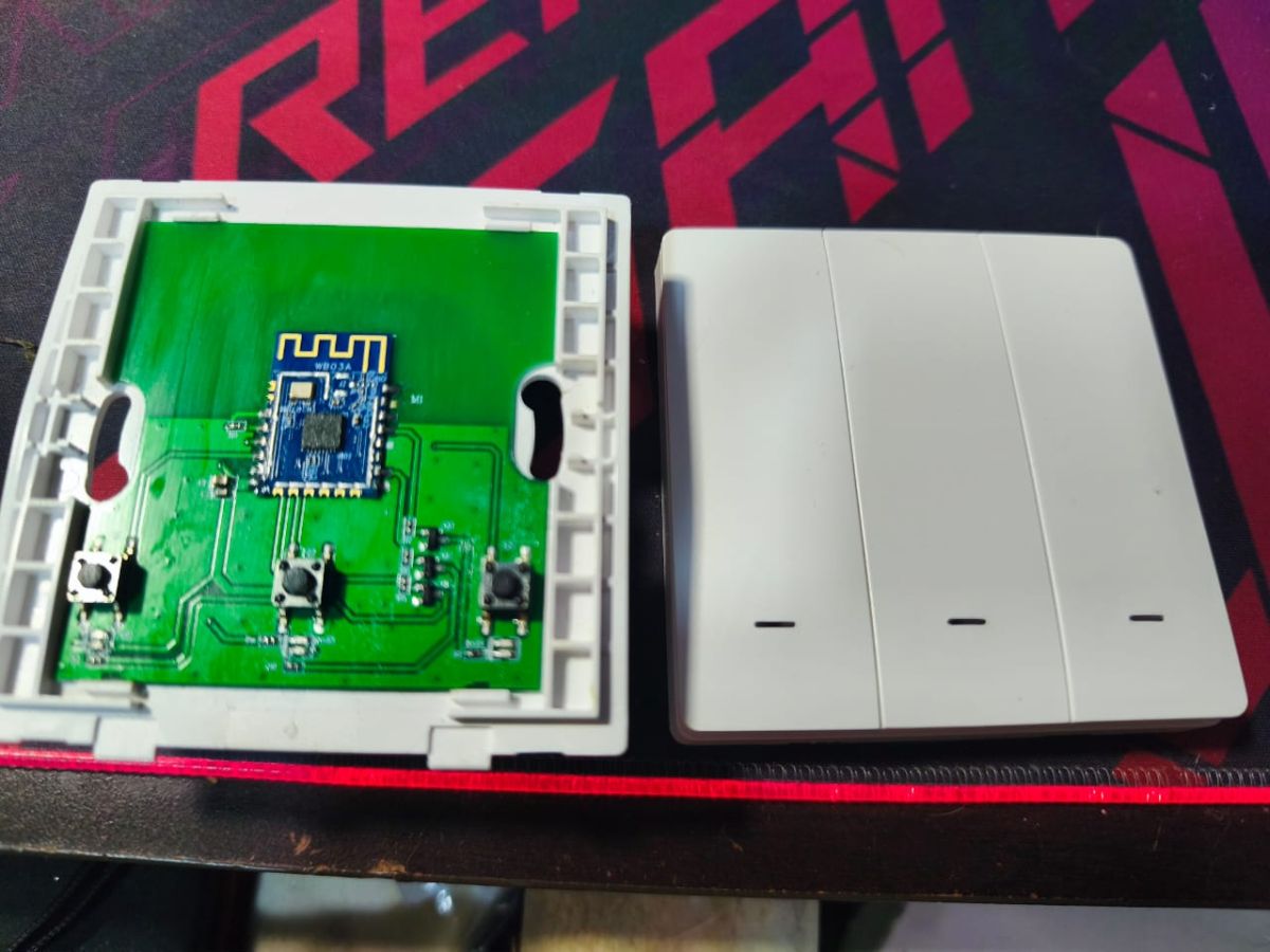
    I got a new 3-gang switch, but this chip is labelled WB03A. I really need help
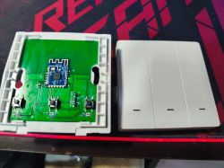
    Opened three-gang wall switch: green PCB with radio module and three tactile buttons next to the cover
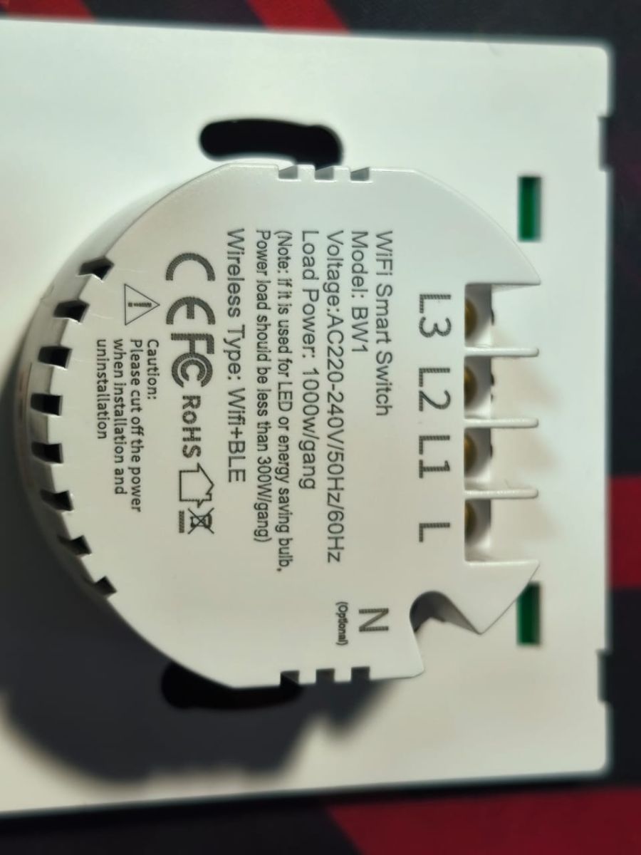
    on its pinouts to solder and what kind of chip this is. Back of a “WiFi Smart Switch” BW1 module with terminals labeled L, L1–L3, and N
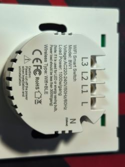
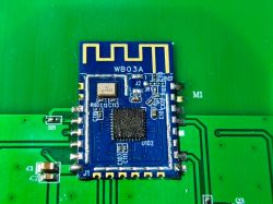
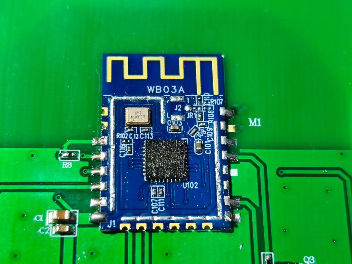
    Blue WB03A electronic module with PCB antenna on a green printed circuit board

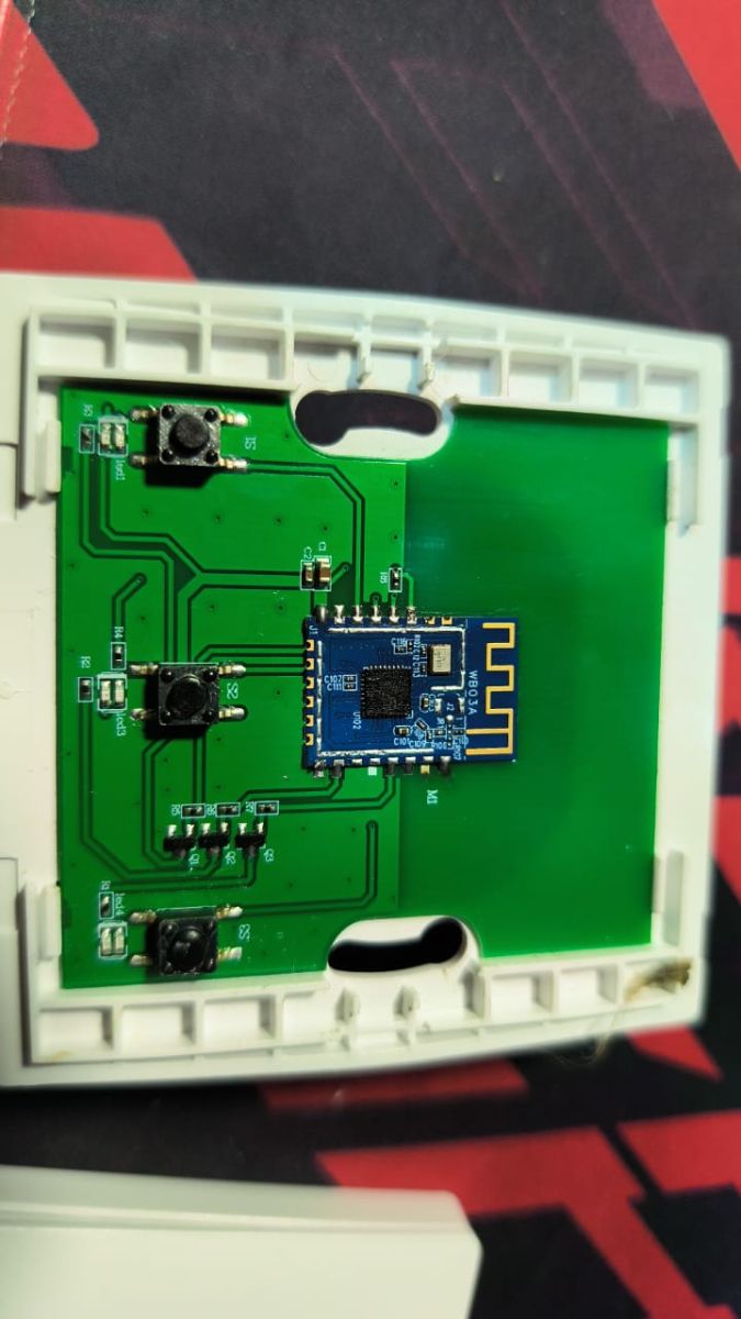
    PCB in a white case with three tactile switches and a blue module with a printed antenna


    AI: Can you provide the brand and full model number of your 3-gang Smart Switch?
    Generic Powered By Tuya Logo
  • ADVERTISEMENT
  • #2 21836555
    divadiow
    Level 38  
    Posts: 4936
    Help: 431
    Rate: 876
    Maybe an RTL8720CM?

    is there any readable text on the square black chip? I can't see anything in the pics.
  • ADVERTISEMENT
  • #3 21836710
    insmod
    Level 31  
    Posts: 1367
    Help: 163
    Rate: 429
    Definitely not BK723x (26mhz XTAL), RTL8720CM (requires external flash chip) or RTL8720CF (QFN40). This one is QFN32 with 40mhz XTAL.
    W800? LN882H?
  • ADVERTISEMENT
  • #4 21837219
    rufus33
    Level 4  
    Posts: 9
    >>21836710
    Here are some extra photos.
    Attachments:
    • WB03A Chip Pinout and Identification for 3Gang Smart Switch Soldering WhatsApp Image 2026-02-13 at 9.20.20 AM.jpeg (175.83 KB) You must be logged in to download this attachment.
    • WB03A Chip Pinout and Identification for 3Gang Smart Switch Soldering WhatsApp Image 2026-02-13 at 9.20.21 AM.jpeg (133.42 KB) You must be logged in to download this attachment.
    • WB03A Chip Pinout and Identification for 3Gang Smart Switch Soldering WhatsApp Image 2026-02-13 at 9.20.21 AM (1).jpeg (150.23 KB) You must be logged in to download this attachment.
    • WB03A Chip Pinout and Identification for 3Gang Smart Switch Soldering WhatsApp Image 2026-02-13 at 9.20.21 AM (2).jpeg (155.04 KB) You must be logged in to download this attachment.
  • #5 21837258
    divadiow
    Level 38  
    Posts: 4936
    Help: 431
    Rate: 876
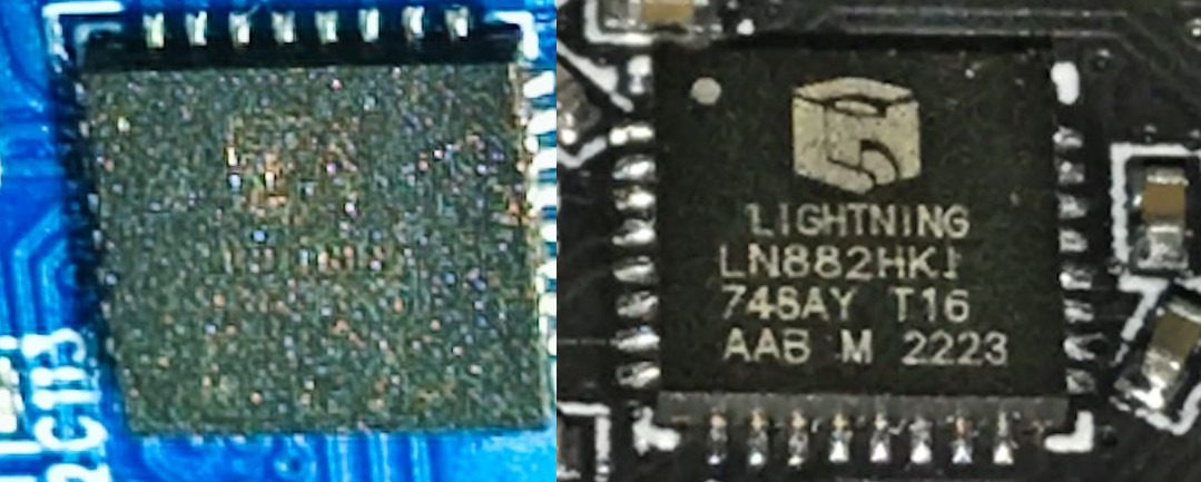
    kinda looks like a Lightning Semi cube

    Close-up of two PCB chips, including one labeled “LIGHTNING LN882HKI”.

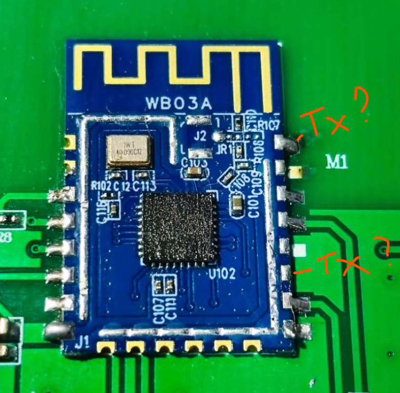
    anyway, you could just capture boot log. Maybe from one of these if theyre TXs like other 12F modules

    Close-up of WB03A PCB module on green board with red handwritten notes “Tx?” and “-Tx?”
  • #6 21837295
    rufus33
    Level 4  
    Posts: 9
    May I ask what software you use to capture boot logs?
  • Helpful post
    #8 21839017
    insmod
    Level 31  
    Posts: 1367
    Help: 163
    Rate: 429
    Doubtful, if Tuya.
    ESP8684 is QFN24, your is QFN32.
    Plus, it almost always comes with 26MHz XTAL, you have 40MHz.

    To capture logs, use any terminal app and USB-UART converter.
    Possible baud rates - 115200 and 921600.
  • #9 21839035
    rufus33
    Level 4  
    Posts: 9
    >>21839017 I managed to desolder the chip, here is the rear view. I really don't know which one is TX and RX.
    Attachments:
    • WB03A Chip Pinout and Identification for 3Gang Smart Switch Soldering WhatsApp Image 2026-02-15 at 3.17.55 PM.jpeg (160.15 KB) You must be logged in to download this attachment.
  • ADVERTISEMENT
  • #11 21839047
    divadiow
    Level 38  
    Posts: 4936
    Help: 431
    Rate: 876
    yay. and definitely do the backup first :)

    Added after 5 [minutes]:

    and, if you're happy to, share the file with us so we can poke at it
  • #12 21908592
    rufus33
    Level 4  
    Posts: 9
    >>21839047 Oh, no.. Now I’m really stuck.
    WB03A Chip Pinout and Identification for 3Gang Smart Switch Soldering
    Code: JSON
    Log in, to see the code


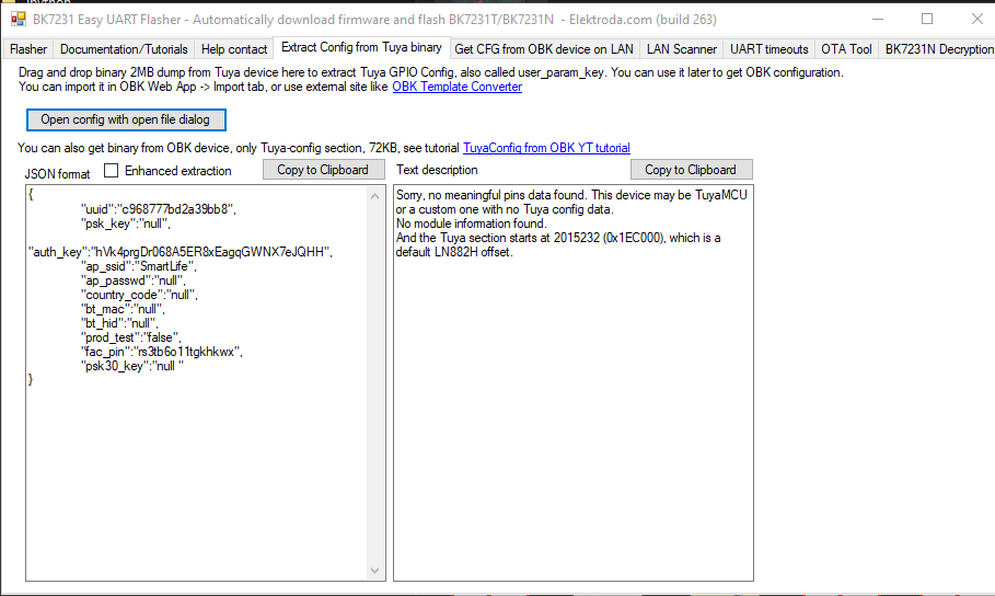
    Sorry, no meaningful pins data found. This device may be TuyaMCU or a custom one with no Tuya config data.
    No module information found.
    And the Tuya section starts at 2015232 (0x1EC000), which is a default LN882H offset.
    readResult...-48-07.bin (2 MB)You must be logged in to download this attachment.
  • #13 21908614
    divadiow
    Level 38  
    Posts: 4936
    Help: 431
    Rate: 876
    enable flag 13 then watch to see which pin's logic level change as you push each button on main gui page. then you've nailed your buttons.

    use GPIO dr/finder in web app to find LEDs and relays. bear in mind you only have the pool of pins labelled on rear of module to check.

    A1 should be one your buttons, I've reset your dump with it to get this clean boot log:

    Code: Text
    Log in, to see the code
  • #14 21908726
    rufus33
    Level 4  
    Posts: 9
    >>21908614 Oh nice nice, flag 13 really helped a lot, managed to find the buttons, WiFi led and the relays. All working now. Thank you so much, really appreciate everyone's help.
  • #15 21909116
    divadiow
    Level 38  
    Posts: 4936
    Help: 431
    Rate: 876
    oh cool. very good.

    What's your final device template so we can add it to the device list?

Topic summary

✨ The discussion focuses on identifying the WB03A chip found in a 3-gang smart switch powered by Tuya. The original poster seeks the chip's pinout and type for soldering purposes. Responses suggest the chip is unlikely to be an RTL8720CM, BK723x, or RTL8720CF due to differences in crystal frequency and package type. The chip in question is a QFN32 package with a 40 MHz crystal oscillator. Possible candidates mentioned include the W800 and LN882H chips, but no definitive identification or pinout details are provided.
Generated by the language model.
ADVERTISEMENT