logo elektroda
logo elektroda
X
logo elektroda

WT200-16A-W thermostat - test with Tuya application, interior and reverse engineering of UART protoc

p.kaczmarek2 729 3

TL;DR

  • WT200-16A-W is a Tuya-compatible WiFi thermostat with manual control, 5+2/6+1/7-day schedules, six daily periods, and an optional external temperature probe.
  • Inside, it uses a TuyaMCU design: a separate WBR3 WiFi module and MCU talk over UART, with an RTCC chip, quartz, and battery preserving time during power loss.
  • Captured packets mapped key dpIDs: 1 on/off, 2 target temperature, 3 current temperature, 4 operating mode, 105 weekly schedule, and 107 workday pattern.
  • Tuya pairing worked easily over Bluetooth, and the thermostat looks suitable for future local firmware flashing and Home Assistant integration.
Generated by the language model.
ADVERTISEMENT
This content has been translated flag-pl » flag-en View the original version here
📢 Listen (AI):
  • Thermostat with black display showing 20.9°C and 22.0°C plus a Wi‑Fi icon
    I would like to invite you to a presentation and a detailed analysis of the interior of the WT200-16A-W thermostat compatible with the Tuya app. The WT200-16A-W offers manual control via WiFi and schedule operation in 5+2, 6+1 or 7-day modes, with 6 time modes per day. The WT200-16A-W is available to buy for around 150PLN and works with an external probe. Let's take a look at what we get in the kit.
    White AVATTO product box with a thermostat LCD display graphic on a wooden surface “WT200 Thermostat User Guide” booklet inside an open cardboard box White mounting part in a cardboard box; plastic bag with two blue screws and a piece of metal mesh Open box with a coiled white cable and a device in plastic marked “Certificate of Quality” Open box with a coiled white cable and a device in plastic marked “Certificate of Quality”
    In this case, the front of the product is fully removable. You can get it in a variety of colours - I've seen copies in black and white. An external sensor is also included, although its use is optional.
    WT200-16A-W-wifi thermostat base with terminals, coiled wired sensor, and manual on a wooden table
    Included in the kit is an English-language manual for pairing and operating the thermostat. Below are clear pictures of it - I won't repeat the information contained therein too closely.
    Unfolded English “WT200 Thermostat User Guide” photographed from above on a wooden surface Photo of a folded “THERMOSTAT USER GUIDE” sheet with a QR code and app setup phone screenshots


    Test with Tuya app
    For many IoT products I often change the firmware straight away and don't even pair it with Tuya, but here I was curious to see what it all looks like. Additionally, I need this to analyse the communication protocol, which I will include in the following paragraphs.
    Pairing was very straightforward - the phone sees these devices by Bluetooth alone:
    Tuya app screen showing device list and an “Add device” panel for “Temp-3” with reading 20.5 “Add Device” screen showing device “Temp-3” added successfully, displaying 20.5°C
    Once paired, we are greeted by the manual mode, or so-called 'manual mode'. It simply allows us to manually set the target temperature we want the thermostat to aim for. The thermostat also gives us a live view of the current temperature from the sensor.
    Tuya app screen in manual mode showing OFF and current temperature 21.7°C Tuya thermostat app screen: Manual mode, setpoint 22.0°C and current temperature 21.9°C
    Of course, there are many more options. The mode button, or 'mode', is used for this. There, we have the aforementioned manual mode, program mode, temporary program mode and leaving the house (in which case heating is switched off or heavily reduced - antifreeze).
    Tuya app screenshot: 22.0°C temperature screen with mode menu (Manual, Program, Temporary, Leave Home)
    The weekly format (6+1, 5+2, etc.) is selectable in the options - this is where you create the programmes.
    App settings screen with thermostat options like 5+2 schedule, calibration, temperature limits, and external sensor selection App screen for week programming settings with “working day setting” and “rest day setting” options.
    The screenshot below shows the aforementioned heating periods. We select an hour and set the temperature that will be implemented at that hour.
    App screen “working day setting” showing six periods with times and temperatures App screen for schedule settings: 06 hours, 00 minutes, and “Set Temperature” 20°C
    Available weekly modes are 5+2, 6+1, 7 or none:
    App settings screen showing “Working day setting” with 5+2 selected
    The options also include calibration and probe selection (external, internal):
    “Settings” screen in an app with thermostat options and sensor selection: internal, external, or both

    Interior product
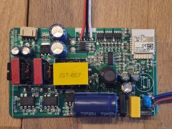
    We will now take a look inside. The product consists of two parts - the front panel with LCD and WiFi module, and the power supply.
    Thermostat PCB in a metal mounting frame with WBR3 WiFi module and sensor cable on a wooden surface
    The ATC9307B and ATC9200DF can be seen on the power supply board. Just by the positions of the components I am betting that the first component is a flyback converter controller with an integrated keying transistor and the second is either an LDO or a synchronous rectifier. Perhaps someone can find more information?
    Close-up of a power PCB showing ATC9307B IC, wide soldered traces, and SMD components
    On the other side of the board you can see the pulse transformer from the inverter and the relay - BRT3-SS-105DM:
    Close-up of a circuit board with a relay and green screw terminal block on a wooden surface
    On the second board we have the MCU and separately the WBR3 WiFi module for communication.
    Close-up of thermostat PCB showing WBR3 Wi‑Fi module, MCU chip, and SMD components Close-up of a PCB with an IC chip, yellow battery cover, and red/black wires inside a casing Close-up of a thermostat PCB with an IC, shielded module, and white connector inside a plastic housing
    You can also see the distinctive RTCC (RealTime Clock Calendar) chip in the SO8 housing, along with the watch quartz and battery from the sustainer.
    Close-up of a PCB with WBR3 Wi‑Fi module, IC chip, and a yellow disc capacitor
    On the other side of the board is just the soldered-on LCD with buttons:
    Disassembled thermostat panel: white bezel with window and a PCB with an LCD on a wooden table
    PCB designation: WT200-WiFi-V1
    Thermostat PCB with WBR3 Wi‑Fi module and connected wires on a wooden surface

    A few words about the internal structure
    The WBR3 module is based on the RTL8720CF chip - its batch can be changed to an open source solution.
    WBR2, WBR3, WBRU, W701-VA2-CG pinout, datasheet, flashing for Home Assistant
    Diagram of the WBR3 module with pin labeling and top and bottom views.
    The architecture of this device is TuyaMCU - we have a separate WiFi module for communication, and a separate MCU controlling all the hardware. Communication between the two is via the UART.
    TuyaMCU protocol - communication between microcontroller and WiFi module
    Block diagram of MCU and Wi-Fi module cooperation.
    Now we are still missing information about the dpID, i.e. the meaning and roles of the variables of this particular product....
    This is where TuyaMCU Analyzer comes in:
    TuyaMCU Analyzer - UART packet decoder for Tuya devices - dpID detector

    Analysis of captured data
    I captured the data with an isolated USB to UART converter. For this I used the ADUM1201 modules. I captured the RX->TX line and the TX->RX line separately (viewed from the WiFi module side). I performed one operation on the application and looked at what was captured. Here are the snippets of data collected.

    Switch - main button:
    
    Sent by WiFi module:
    55 AA   00   06      00 05   0101000100   0D   
    HEADER   VER=00   SetDP      LEN   dpId=1 Bool V=0      CHK   
    

    Conclusion: dpID 1 of type bool is the on/off state.

    Target temperature setting:
    
    Sent by WiFi module:
    55 AA   00   06      00 08   02020004000001A9   BF   
    HEADER   VER=00   SetDP      LEN   dpId=2 Val V=425      CHK   
    

    Conclusion: dpID 2 is the target temperature (multiplied by a constant to support decimal values).

    Change mode to program mode:
    
    Sent by WiFi module:
    55 AA   00   06      00 05   0404000101   14   
    HEADER   VER=00   SetDP      LEN   dpId=4 Enum V=1      CHK   
    

    dpID 4 is an enumeration. I have tested more and have unset the enumeration.
    Manual Mode = 0, Program Mode = 1, Temporary Program Mode = 2, Leave Home = 3

    Disabling sound:
    
    Sent by WiFi module:
    55 AA   00   06      00 05   6D01000100   79   
    HEADER   VER=00   SetDP      LEN   dpId=109 Bool V=0      CHK   
    

    Boolean with dpID 109 is sound on/off.

    Backlight brightness on low:
    
    Sent by WiFi module:
    55 AA   00   06      00 05   6A04000101   7A   
    HEADER   VER=00   SetDP      LEN   dpId=106 Enum V=1      CHK   
    

    dpID 106 is backlight enumeration - probably sequentially off, low, medium....

    Temp calibration at 0.3°C:
    
    Sent by WiFi module:
    55 AA   00   06      00 08   1302000400000003   29   
    HEADER   VER=00   SetDP      LEN   dpId=19 Val V=3      CHK   
    

    The value 3 represents the number of decimals, so 0.3.

    Frost protection on:
    
    Sent by WiFi module:
    55 AA   00   06      00 05   6701000101   74   
    HEADER   VER=00   SetDP      LEN   dpId=103 Bool V=1      CHK   
    

    Again boolean - on/off.

    Output main inverse on:
    
    Sent by WiFi module:
    55 AA   00   06      00 05   6C01000101   79   
    HEADER   VER=00   SetDP      LEN   dpId=108 Bool V=1      CHK   
    

    Boolean dpID 108 - on/off possibility.

    Sensor on internal:
    
    Sent by WiFi module:
    55 AA   00   06      00 05   6E04000100   7D   
    HEADER   VER=00   SetDP      LEN   dpId=110 Enum V=0      CHK   


    Temperature control switch inverse:
    
    Sent by WiFi module:
    55 AA   00   06      00 08   6502000400000050   C8   
    HEADER   VER=00   SetDP      LEN   dpId=101 Val V=80      CHK   


    Child lock (child protection - button lock) on:
    
    Sent by WiFi module:
    55 AA   00   06      00 05   0901000101   16   
    HEADER   VER=00   SetDP      LEN   dpId=9 Bool V=1      CHK   


    Workday setting to 6+1;
    
    Sent by WiFi module:
    55 AA   00   06      00 05   6B04000102   7C   
    HEADER   VER=00   SetDP      LEN   dpId=107 Enum V=2      CHK   


    Workday settings at 5+2:
    
    Sent by WiFi module:
    55 AA   00   06      00 05   6B04000101   7B   
    HEADER   VER=00   SetDP      LEN   dpId=107 Enum V=1      CHK   


    MCU reporting temperature to WiFi module:
    
    Received by WiFi module:
    55 AA   03   07      00 08   03 02 00 04 0000011D       38   
    HEADER   VER=03   State      LEN   dpId=3 Val V=285   CHK   
    
    Received by WiFi module:
    55 AA   03   00      00 01   01   04   
    HEADER   VER=03   Heartbeat      LEN   01   CHK   
    
    Received by WiFi module:
    55 AA   03   07      00 08   03 02 00 04 0000011A       35   
    HEADER   VER=03   State      LEN   dpId=3 Val V=282   CHK   
    
    Received by WiFi module:
    55 AA   03   00      00 01   01   04   
    HEADER   VER=03   Heartbeat      LEN   01   CHK   
    

    The current temperature is dpID 3.

    I set the period 1 working day setting to 7:02 and 21°C
    
    Sent by WiFi module:
    55 AA   00   00      00 00      FF   
    HEADER   VER=00   Heartbeat      LEN      CHK   
    
    Sent by WiFi module:
    55 AA   00   06      00 24   69000020070200D2080000A00B1E00A00C1E00A0110000DC160000A0080000DC170000A0   06   
    HEADER   VER=00   SetDP      LEN   dpId=105 Raw V=07 02 00 D2 08 00 00 A0 0B 1E 00 A0 0C 1E 00 A0 11 00 00 DC 16 00 00 A0 08 00 00 DC 17 00 00 A0      CHK   


    I set period 4 working day setting to 12:33 and 18°C:
    
    Sent by WiFi module:
    55 AA   00   06      00 24   69000020070200D2080000A00B1E00A00C2100B4110000DC160000A0080000DC170000A0   1D   
    HEADER   VER=00   SetDP      LEN   dpId=105 Raw V=07 02 00 D2 08 00 00 A0 0B 1E 00 A0 0C 21 00 B4 11 00 00 DC 16 00 00 A0 08 00 00 DC 17 00 00 A0      CHK   


    I set period 1 to 00:00 and 5°C :
    
    Sent by WiFi module:
    55 AA   00   06      00 24   6900002000000032080000A00B1E00A00C2100B4110000DC160000A0080000DC170000A0   74   
    HEADER   VER=00   SetDP      LEN   dpId=105 Raw V=00 00 00 32 08 00 00 A0 0B 1E 00 A0 0C 21 00 B4 11 00 00 DC 16 00 00 A0 08 00 00 DC 17 00 00 A0      CHK   


    Let's compare it again, the payload itself.
    Period 1 at 7:02 and 21°C:
    69 00 00 20 07 02 00 D2 080000A00B1E00A00C1E00A0110000DC160000A0080000DC170000A0
    Period 4 at 12:33 and 18°C:
    69 00 00 20 07 02 00 D2 080000A00B1E00A00C2100B4110000DC160000A0080000DC170000A0
    Period 1 at 00:00 and 5°C:
    69 00 00 20 00 00 00 32 080000A00B1E00A00C2100B4110000DC160000A0080000DC170000A0
    Here 0x07 and 0x02 have changed to 0x00 0x00, so presumably one byte is hours and the other is minutes, plus 0xD2 has changed to 0x32. 0xD2 is 210, so probably decimals, 21°C, and 0x32 is 50, so that's right - 5°C. One period format is hour, minute, zero byte (?) and temperature. Ew. temperature as two bytes.

    Follow up work
    The next step is to upload our open source firmware:
    https://github.com/openshwprojects/OpenBK7231T_App
    The TuyaMCU configuration process is presented there:
    TuyaMCU flashing, installation and configuration guide - configure dpID for Home Assistant
    Perhaps I will present this in a separate topic.

    Summary
    The thermostat presented here generally appealed to me. The whole thing offers quite a lot of different options, including different operating programmes, calibrations, working with an external or built-in probe, and even child protection and an anti-freeze mode (maintaining a minimum temperature in the house when we are away).
    Internally, I was most surprised by this RTCC - however, the manufacturer makes sure that the programmes will execute even when power is lost. The programme itself is in non-volatile memory, that's not a problem, but the hour also needs to be maintained somehow - and the RTCC with the battery solves that. I'm betting that the programme will come on even if there is no internet access when power returns.
    As for the inside, there's a WBR3 module inside, you can easily change the firmware for it, but then you have to configure the TuyaMCU, which I haven't tried yet in this case, although I know that other thermostats have been successfully run this way. I have collected and analysed the packages for now, so that I have a basis for further work. Eventually this will allow me to run this thermostat locally, without the manufacturer's servers, and pair it with Home Assistant.
    Do you use this type of thermostat, and if so, with Tuya or with Home Assistant?

    Cool? Ranking DIY
    Helpful post? Buy me a coffee.
    About Author
    p.kaczmarek2
    Moderator Smart Home
    Offline 
    p.kaczmarek2 wrote 14332 posts with rating 12235, helped 648 times. Been with us since 2014 year.
  • ADVERTISEMENT
  • #2 21879844
    Stanley_P
    Level 28  
    Hi. With me, a similar Tuya temperature controller has just successfully run its first full winter season. Installed in place of a completely working and fairly new one, but without wifi. A bit installed on a whim, one might say, but with a price tag of just over 100£ you could go wild... ;-) I have described more in THIS TOPIC , there are a few pics.
    The controller in relation to the one presented here has very similar functions and options in the application. The information on the display is presented graphically a little differently, e.g. in my opinion the current temperature is better distinguished from the set temperature, but these are details.

    Fortunately or unfortunately, the controller works with the original Tuya (specifically, I use the SmartLife app). Converting to Home Assistant - well, I'd have to do a lot of learning, buy/set up a server in general, etc. I don't really see the point in my case - there are several "IoT" devices in the flat, such as sockets or wifi bulbs, which I can do without in everyday life should the "cloud" stop working for one reason or another. My temperature controller similarly to the one described in this article is also able to work fully autonomously. Timer, schedules, on/off "heating", etc. - everything can be set manually from the panel. So a failure of the internet, wifi, etc. doesn't mean I'll instantly freeze to death ;-) Anyway, in the event of a last resort, I can reinstall the old controller.
  • ADVERTISEMENT
  • #3 21879847
    p.kaczmarek2
    Moderator Smart Home
    One note - once the firmware has been changed (e.g. to Multi-platform IoT firmware supporting up to 32 platforms ), you don't necessarily need HA - you can then continue to use either the device's touch panel or its website on the LAN, e.g. from a tablet, PC, phone.
    Helpful post? Buy me a coffee.
  • #4 21880500
    Stanley_P
    Level 28  
    p.kaczmarek2 wrote:
    or from its website on the LAN, e.g. from a tablet, computer, phone

    That is, as I understand it, uploading such alternative firmware will enable local network access to the device's web panel. But what about automation, any at least simple procedures, scenes (by analogy with Tuya)? For example, in relation to the thermostat, is it possible to create and fire a scene on such firmware that will switch on the "heating" relay for a specific time, e.g. 30min? However, do you need a server like HA for such things?
📢 Listen (AI):

FAQ

TL;DR: With 15 identified dpIDs and a "TuyaMCU" UART design, this FAQ helps WT200-16A-W owners pair the thermostat, map its protocol, and plan local-control mods for Tuya or Home Assistant. It solves the practical gap between app use, hardware teardown, and reverse engineering. [#21877759]

Why it matters: This thread turns a consumer Tuya thermostat into a documented platform for troubleshooting, UART analysis, and future local integration.

Option Control path Strength Trade-off
Stock Tuya firmware Tuya app over Bluetooth/Wi‑Fi Fast pairing and full app scheduling Depends on vendor cloud workflow
WBR3 with open firmware OpenBK7231T_App + TuyaMCU mapping Local control and Home Assistant potential Requires flashing and dpID configuration

Key insight: The WT200-16A-W is not a monolithic Wi‑Fi thermostat. It uses a separate WBR3 Wi‑Fi module and a main MCU that exchange settings over UART, so successful local control depends on decoding dpIDs correctly.

Quick Facts

  • Approximate price is £150, and the thermostat supports an external probe in addition to its built-in sensing options. [#21877759]
  • Scheduling supports 5+2, 6+1, 7-day, or no schedule, with 6 time modes per day. [#21877759]
  • The target temperature uses scaled values in Tuya packets, so 21.0°C = 210 and 42.5°C = 425. [#21877759]
  • The hardware is split into two boards: a power board with a BRT3-SS-105DM relay and a front board with LCD, MCU, WBR3 Wi‑Fi, RTCC, watch crystal, and backup battery. [#21877759]
  • Captured UART traffic used an isolated USB-to-UART adapter with ADUM1201 isolation modules, and RX→TX plus TX→RX were logged separately from the Wi‑Fi module side. [#21877759]

How do you pair the WT200-16A-W thermostat with the Tuya app over Bluetooth and Wi‑Fi?

You pair it by putting the thermostat in pairing mode and letting the phone discover it over Bluetooth first. The thread says pairing was very straightforward, and the phone saw the device by Bluetooth alone before app control became available. After pairing, the Tuya app exposed manual mode, program mode, temporary program mode, and leave-home functions over Wi‑Fi-linked control. [#21877759]

What operating modes does the WT200-16A-W support in the Tuya app, including manual, program, temporary program, and leave-home mode?

The WT200-16A-W supports four app modes: manual, program, temporary program, and leave-home. Manual mode lets you set the target temperature directly while viewing live sensor temperature. Program mode follows the weekly schedule, temporary program mode applies a temporary override, and leave-home reduces or switches off heating for antifreeze protection. [#21877759]

How do the 5+2, 6+1, 7-day, and no-schedule weekly modes work on the WT200-16A-W thermostat?

These weekly modes define how the thermostat groups days for scheduled heating. In the app, you can select 5+2, 6+1, 7-day, or none, then assign up to 6 time periods per day with a start time and target temperature. “None” means you do not use a repeating weekly program and rely on direct control instead. [#21877759]

What is TuyaMCU, and how does UART communication work between the WBR3 WiFi module and the main MCU in this thermostat?

"TuyaMCU" is a device architecture that separates cloud or app communication from hardware control, using a Wi‑Fi module and a main microcontroller linked by UART. In this thermostat, the WBR3 handles connectivity and sends SetDP packets over UART, while the main MCU controls sensors, LCD, relay logic, and reports state back, such as dpID 3 temperature updates and heartbeat frames. [#21877759]

What is a dpID in the TuyaMCU protocol, and how do you identify which dpIDs control temperature, mode, child lock, and other settings?

A dpID is the data-point identifier that tells TuyaMCU which function a packet controls or reports. You identify dpIDs by capturing UART traffic, changing one setting in the app at a time, and matching the changed payload. In this thread, that method mapped dpID 2 to target temperature, dpID 4 to mode, dpID 9 to child lock, and several others to calibration, sensor choice, and scheduling. [#21877759]

Which dpIDs were identified for the WT200-16A-W, and what do dpID 1, 2, 3, 4, 9, 19, 101, 103, 105, 106, 107, 108, 109, and 110 mean?

The identified dpIDs are: 1 on/off, 2 target temperature, 3 current temperature, 4 operating mode, 9 child lock, 19 temperature calibration, 101 temperature control switch inverse, 103 frost protection, 105 raw schedule data, 106 backlight brightness, 107 workday mode, 108 output main inverse, 109 sound on/off, and 110 sensor selection. Mode enum values were mapped as 0 manual, 1 program, 2 temporary program, and 3 leave-home. [#21877759]

How can you capture and decode UART packets from a Tuya thermostat safely using an isolated USB-to-UART adapter and ADUM1201 modules?

Use galvanic isolation and capture both directions separately. 1. Connect an isolated USB-to-UART adapter through ADUM1201 isolation modules. 2. Log RX→TX and TX→RX separately from the WBR3 Wi‑Fi module side. 3. Change one app setting at a time and compare the resulting UART frame to decode the dpID, type, and value safely. [#21877759]

Why is the target temperature in the WT200-16A-W Tuya protocol sent as a scaled value like 425 for 42.5°C or 210 for 21.0°C?

The thermostat sends target temperature as a scaled integer so the protocol can carry decimal temperatures without floating-point values. The thread explicitly shows dpID 2 values such as 425 for 42.5°C and schedule bytes where 0xD2 equals 210, meaning 21.0°C. This design keeps packets compact and consistent across integer-based UART messages. [#21877759]

How is the raw schedule data in dpID 105 structured for the WT200-16A-W, and which bytes represent hour, minute, and temperature?

dpID 105 stores schedule periods as a raw byte block where each period includes hour, minute, a zero byte, and a two-byte temperature value. The thread compares 07:02 at 21°C with 00:00 at 5°C, showing 0x07 and 0x02 changing to 0x00 and 0x00, while 0x00D2 changes to 0x0032. That directly ties hour, minute, and scaled temperature to the payload. [#21877759]

What is the RTCC chip doing inside the WT200-16A-W thermostat, and how does its backup battery help preserve schedules after a power loss?

The RTCC keeps time running when main power is lost, so scheduled heating can resume correctly after power returns. The board includes an SO8 RTCC, a watch crystal, and a backup battery. The thread notes that schedule data itself is not the issue because it sits in non-volatile memory; maintaining the current time is the critical function. [#21877759]

How does the WBR3 module based on RTL8720CF compare with keeping the stock Tuya firmware when you want local control and Home Assistant integration?

Keeping the stock firmware gives you quick Tuya app setup, while replacing firmware on the WBR3 opens a path to local control and Home Assistant. The thread states that the WBR3 is based on RTL8720CF and can be switched to an open-source solution. The trade-off is effort: after flashing, you still must configure TuyaMCU correctly, or the thermostat functions will not map properly. [#21877759]

What should you check inside the WT200-16A-W hardware, including the power board, relay BRT3-SS-105DM, and external probe support, before attempting firmware changes?

Check the board split, relay section, probe support, and module access before flashing anything. 1. Confirm the device has a separate front board and power board. 2. Identify the BRT3-SS-105DM relay and the WBR3 module on PCB WT200-WiFi-V1. 3. Verify whether the thermostat uses the internal sensor or external probe, because that affects later testing after firmware changes. [#21877759]

When should you use the external probe versus the internal sensor on the WT200-16A-W, and how does that affect temperature control?

Use the external probe when you want temperature control from the remote sensor location, and use the internal sensor when the thermostat’s own placement reflects room conditions. The app includes explicit probe selection between external and internal, mapped as dpID 110. That choice changes which temperature source the control loop follows, so poor sensor placement can cause incorrect heating behavior. [#21877759]

What is the process for replacing the stock firmware on the WBR3 with OpenBK7231T_App and then configuring TuyaMCU for Home Assistant?

The process is to flash the WBR3 first, then rebuild function mapping through TuyaMCU configuration. 1. Replace the stock WBR3 firmware with OpenBK7231T_App. 2. Use the captured UART analysis to map dpIDs such as 1, 2, 3, 4, and 105. 3. Configure those dpIDs in TuyaMCU so Home Assistant can expose power, temperature, mode, and scheduling-related functions. [#21877759]

How are people actually using thermostats like the WT200-16A-W with Tuya versus Home Assistant, and what are the practical pros and cons of each setup?

People use Tuya when they want fast app control, and they choose Home Assistant when they want local automation and vendor-independent control. The thread’s author tested the Tuya app first, then captured packets as groundwork for a local setup without manufacturer servers. A practical advantage of Tuya is immediate Bluetooth-assisted pairing; a practical advantage of Home Assistant is future local operation after internet loss, provided the RTCC and TuyaMCU mapping are correct. [#21877759]
Generated by the language model.
ADVERTISEMENT