
logo elektroda
logo elektroda
X
logo elektroda

Ambiano SWW04U CBU BK7231N OpenBeken: which GPIOs set contact/deepsleep?

Spockur 573 11
ADVERTISEMENT
Treść została przetłumaczona german » english Zobacz oryginalną wersję tematu
  • #1 21891113
    Spockur
    Level 2  
    Posts: 6
    Hello everyone,
    I have successfully flashed an ambiano sww04u with Beken CBU bk7231n using Openbeken and the Openflashtool. The CBU starts and connects to the WLAN.

    Note: I had to remove R27 and R28 for the flashing process.
    My question: How do I determine the GPIOs and settigs for the contact and the deepsleep settings?

    Does anyone have a tip?
    Thank you and have a nice Sunday.
  • ADVERTISEMENT
  • #2 21891774
    p.kaczmarek2
    Moderator Smart Home
    Posts: 14506
    Help: 651
    Rate: 12506
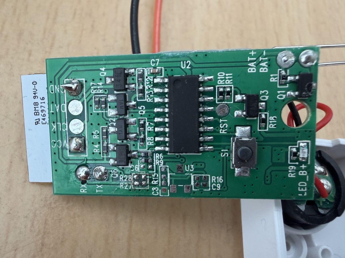
    Can you show photos of the inside? Do you have a copy of the 2MB batch file (before pairing, otherwise it might contain the SSID and password)? Firstly, you need to determine whether this device supports TuyaMCU.
    Helpful post? Buy me a coffee.
  • ADVERTISEMENT
  • #3 21893303
    Spockur
    Level 2  
    Posts: 6
    Hi,

    Thank you for your feedback.
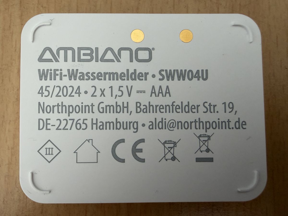
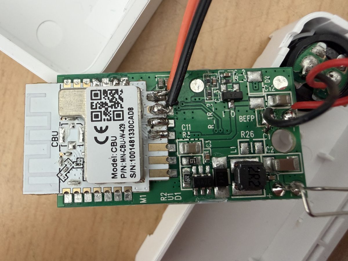
    Pictures attached. I would have the backup as Tuya Original. Does that help? Upload it right away. Or reset again and upload a backup to Openbeken flash?

    Ambiano SWW04U CBU BK7231N OpenBeken: which GPIOs set contact/deepsleep? Ambiano SWW04U CBU BK7231N OpenBeken: which GPIOs set contact/deepsleep? Ambiano SWW04U CBU BK7231N OpenBeken: which GPIOs set contact/deepsleep?

    Added after 21 [minutes]:

    Attached is the backup of the original Tuya firmware.
    readResult...-34-00.bin (2 MB)You must be logged in to download this attachment.
  • ADVERTISEMENT
  • #4 21893336
    Spockur
    Level 2  
    Posts: 6
    Hi,
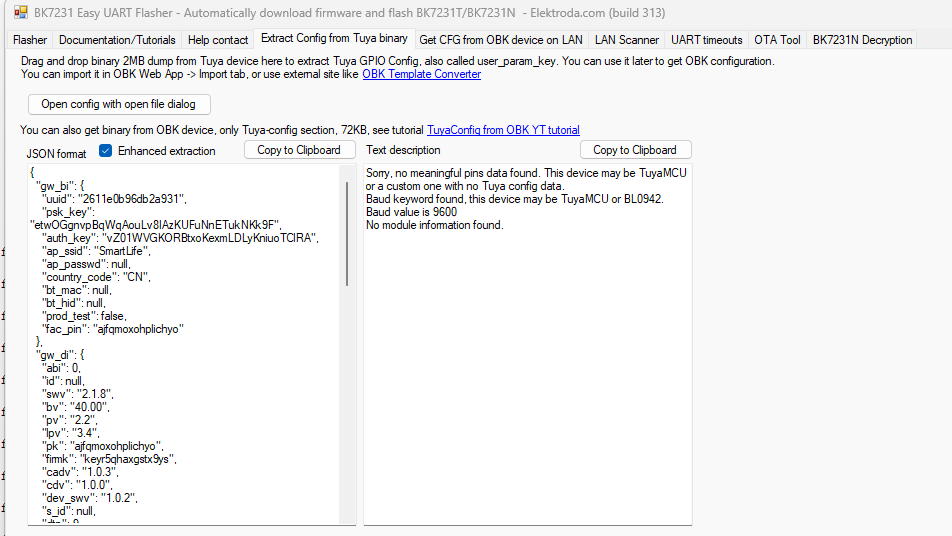
    Extract Config from Tuya binary:
    {
      "gw_bi": {
        "uuid": "2611e0b96db2a931",
        "psk_key": "etwOGgnvpBqWqAouLv8IAzKUFuNnETukNKk9F",
        "auth_key": "vZ01WVGKORBtxjKexmLDLyKniuoTClRA",
        "ap_ssid": "SmartLife",
        "ap_passwd": null,
        "country_code": "CN",
        "bt_mac": null,
        "bt_hid": null,
        "prod_test": false,
        "fac_pin": "ajfqmoxohplichyo"
      },
      "gw_di": {
        "abi": 0,
        "id": null,
        "swv": "2.1.8",
        "bv": "40.00",
        "pv": "2.2",
        "lpv": "3.4",
        "pk": "ajfqmoxohplichyo",
        "firmk": "keyr5qhaxgstx9ys",
        "cadv": "1.0.3",
        "cdv": "1.0.0",
        "dev_swv": "1.0.2",
        "s_id": null,
        "dtp": 9,
        "sync": 0,
        "attr_num": 0,
        "mst_tp_0": 0,
        "mst_ver_0": null,
        "mst_tp_1": 0,
        "mst_ver_1": null,
        "mst_tp_2": 0,
        "mst_ver_2": null,
        "mst_tp_3": 0,
        "mst_ver_3": null
      },
      "wf_start_md": 129,
      "gw_wsm": {
        "nc_tp": 1,
        "ssid": null,
        "passwd": null,
        "md": 0,
        "random": 0,
        "wfb64": 1,
        "stat": 1,
        "token": null,
        "region": null,
        "reg_key": null,
        "dns_prio": 0
      },
      "gw_ai": {
        "key": null,
        "lckey": null,
        "h_url": null,
        "h_ip": null,
        "hs_url": null,
        "hs_ip": null,
        "hs_psk": null,
        "hs_psk_ip": null,
        "mqs_url": null,
        "mqs_ip": null,
        "mq_url": null,
        "mq_ip": null,
        "ai_sp": null,
        "ai_sp_ip": null,
        "mq_psk": null,
        "mq_psk_ip": null,
        "time_z": null,
        "s_time_z": null,
        "wx_app_id": null,
        "wx_uuid": null,
        "dy_tls_m": 0,
        "cloud_cap": 0,
        "psk21_key": null
      },
      "record_head": "",
      "baud_cfg": {
        "baud": 9600
      }
    }
    

    Ambiano SWW04U CBU BK7231N OpenBeken: which GPIOs set contact/deepsleep?
  • #5 21894259
    p.kaczmarek2
    Moderator Smart Home
    Posts: 14506
    Help: 651
    Rate: 12506
    I would recommend doing a TuyaMCU communication intercept with a USB to UART converter. This will help clear up doubts about the protocol later.
    https://github.com/openshwprojects/TuyaMCUAnalyzer
    English tutorial: https://www.elektroda.com/rtvforum/topic4038151.html
    Helpful post? Buy me a coffee.
  • #6 21895886
    Spockur
    Level 2  
    Posts: 6
    Hello,
    I will do that. I still have a second unflashed sensor.
    Question: do the two resistors on TX1 and RX1 have to be removed beforehand?
  • ADVERTISEMENT
  • #7 21897286
    p.kaczmarek2
    Moderator Smart Home
    Posts: 14506
    Help: 651
    Rate: 12506
    The resistors on RX/TX are removed when we want to cut off the interfering TuyaMCU flashing on the UART line. The TuyaMCU uses the same UART to communicate with the WiFi module as we use to flash the WiFi module. For this reason, it is common to remove these resistors temporarily for flashing or to solder out the MCU itself.

    If, in your case, flashing works without removing them, then you do not need to do this.
    Helpful post? Buy me a coffee.
  • #8 21902545
    Spockur
    Level 2  
    Posts: 6
    >>21897286 Hello,
    i have opened the module with the original Tuya firmware, removed the resistors and connected it to the TuyaMCU Analyser TX1/RX1.
    As a result, I only get the following values at 9600 baud.

    Received by WiFi module:
    55 AA 00 01 00 00 00
    HEADER VER=00 Product LEN CHK

    Received by WiFi module:
    55 AA 00 01 00 00 00
    HEADER VER=00 Product LEN CHK

    Received by WiFi module:
    55 AA 00 01 00 00 00
    HEADER VER=00 Product LEN CHK

    Do I have to leave the TX/RX line connected to the resistors and set up the Tuya device first and analyse it with the connected resistors?
  • #9 21902733
    p.kaczmarek2
    Moderator Smart Home
    Posts: 14506
    Help: 651
    Rate: 12506
    You are using the TuyaMCU analyser incorrectly.

    The principle is simple:
    - if you want to test TuyaMCU communication, you can't disconnect the RX-TX lines from each other, because you will break communication, and nothing will work. You have to listen with resistors
    - if you want to change the firmware, i.e. upload OpenBeken, then you disconnect the TuyaMCU (remove the resistors), because the firmware is uploaded through the same port as the TuyaMCU is running on it
    Helpful post? Buy me a coffee.
  • #10 21902951
    Spockur
    Level 2  
    Posts: 6
    >>21902733 Thank you for your patience and your tips.
    I am now listening with resistors. Unfortunately not much is coming through.
    I have now also connected the device to the original APP and Tuya.
    The only value is:
    Received by WiFi module:
    55 AA 00 10 00 02 0100 12
    HEADER VER=00 ObtainDPcache LEN CHK
  • #11 21903038
    p.kaczmarek2
    Moderator Smart Home
    Posts: 14506
    Help: 651
    Rate: 12506
    Does the device work?

    Communication is reciprocal and works on the device with the factory batch. If something is not working, it may be that one of the UART lines is further interrupted due to cold soldering.
    Helpful post? Buy me a coffee.
  • #12 21904788
    Spockur
    Level 2  
    Posts: 6
    >>21903038 I have now realised the power connection with the AAA battery. Only TX1 and RX1 are now connected for monitoring.
    The result already looks better:
    Received by WiFi module:
    55 AA   00   01      00 00      00   
    HEADER   VER=00   Product      LEN      CHK   
    
    Received by WiFi module:
    55 AA   00   02      00 01   02   04   
    HEADER   VER=00   McuConf      LEN   02   CHK   
    
    Received by WiFi module:
    55 AA   00   02      00 01   03   05   
    HEADER   VER=00   McuConf      LEN   03   CHK   
    
    Received by WiFi module:
    55 AA   00   02      00 01   04   06   
    HEADER   VER=00   McuConf      LEN   04   CHK   
    
    Received by WiFi module:
    55 AA   00   10      00 02   0100   12   
    HEADER   VER=00   ObtainDPcache      LEN         CHK   
    
    Received by WiFi module:
    55 AA   00   05      00 01   00   05   
    HEADER   VER=00   Unk      LEN         CHK   
    
    Received by WiFi module:
    55 AA   00   05      00 01   00   05   
    HEADER   VER=00   Unk      LEN         CHK   
    
    Received by WiFi module:
    55 AA   00   10      00 02   0100   12   
    HEADER   VER=00   ObtainDPcache      LEN         CHK   
    
    Sent by WiFi module:
    55 AA   00   01      00 00      00   
    HEADER   VER=00   Product      LEN      CHK   
    
    Sent by WiFi module:
    55 AA   00   02      00 01   02   04   
    HEADER   VER=00   McuConf      LEN   02   CHK   
    
    Sent by WiFi module:
    55 AA   00   02      00 01   03   05   
    HEADER   VER=00   McuConf      LEN   03   CHK   
    
    Sent by WiFi module:
    55 AA   00   02      00 01   04   06   
    HEADER   VER=00   McuConf      LEN   04   CHK   
    
    Sent by WiFi module:
    55 AA   00   10      00 02   0100   12   
    HEADER   VER=00   ObtainDPcache      LEN         CHK   
    
    Sent by WiFi module:
    55 AA   00   05      00 01   00   05   
    HEADER   VER=00   Unk      LEN         CHK   
    
    Sent by WiFi module:
    55 AA   00   05      00 01   00   05   
    HEADER   VER=00   Unk      LEN         CHK   
    
    Sent by WiFi module:
    55 AA   00   10      00 02   0100   12   
    HEADER   VER=00   ObtainDPcache      LEN         CHK   
    
    Received by WiFi module:
    55 AA   00   01      00 00      00   
    HEADER   VER=00   Product      LEN      CHK   
    
    Received by WiFi module:
    55 AA   00   02      00 01   02   04   
    HEADER   VER=00   McuConf      LEN   02   CHK   
    
    Received by WiFi module:
    55 AA   00   02      00 01   03   05   
    HEADER   VER=00   McuConf      LEN   03   CHK   
    
    Received by WiFi module:
    55 AA   00   02      00 01   04   06   
    HEADER   VER=00   McuConf      LEN   04   CHK   
    
    Received by WiFi module:
    55 AA   00   10      00 02   0100   12   
    HEADER   VER=00   ObtainDPcache      LEN         CHK   
    
    Received by WiFi module:
    55 AA   00   05      00 01   00   05   
    HEADER   VER=00   Unk      LEN         CHK   
    
    Received by WiFi module:
    55 AA   00   05      00 01   00   05   
    HEADER   VER=00   Unk      LEN         CHK   
    
    Received by WiFi module:
    55 AA   00   10      00 02   0100   12   
    HEADER   VER=00   ObtainDPcache      LEN         CHK   
    Received by WiFi module:
    55 AA   00   01      00 00      00   
    HEADER   VER=00   Product      LEN      CHK   
    
    Received by WiFi module:
    55 AA   00   01      00 00      00   
    HEADER   VER=00   Product      LEN      CHK   
    
    Received by WiFi module:
    55 AA   00   02      00 01   03   05   
    HEADER   VER=00   McuConf      LEN   03   CHK   
    
    Received by WiFi module:
    55 AA   00   02      00 01   04   06   
    HEADER   VER=00   McuConf      LEN   04   CHK   
    
    Received by WiFi module:
    55 AA   00   10      00 07   01010804000101   26   
    HEADER   VER=00   ObtainDPcache      LEN   dpId=8 Enum V=1      CHK   
    
    Received by WiFi module:
    55 AA   00   05      00 01   00   05   
    HEADER   VER=00   Unk      LEN         CHK   
    
    Received by WiFi module:
    55 AA   00   05      00 01   00   05   
    HEADER   VER=00   Unk      LEN         CHK   
    
    Received by WiFi module:
    55 AA   00   05      00 01   00   05   
    HEADER   VER=00   Unk      LEN         CHK   
    
    Received by WiFi module:
    55 AA   00   10      00 02   0100   12   
    HEADER   VER=00   ObtainDPcache      LEN         CHK   
    
    Sent by WiFi module:
    55 AA   00   01      00 00      00   
    HEADER   VER=00   Product      LEN      CHK   
    
    Sent by WiFi module:
    55 AA   00   02      00 01   04   06   
    HEADER   VER=00   McuConf      LEN   04   CHK   
    
    Sent by WiFi module:
    55 AA   00   10      00 07   01010804000101   26   
    HEADER   VER=00   ObtainDPcache      LEN   dpId=8 Enum V=1      CHK   
    
    Sent by WiFi module:
    55 AA   00   05      00 01   00   05   
    HEADER   VER=00   Unk      LEN         CHK   
    
    Sent by WiFi module:
    55 AA   00   05      00 01   00   05   
    HEADER   VER=00   Unk      LEN         CHK   
    
    Sent by WiFi module:
    55 AA   00   05      00 01   00   05   
    HEADER   VER=00   Unk      LEN         CHK   
    
    Sent by WiFi module:
    55 AA   00   10      00 02   0100   12   
    HEADER   VER=00   ObtainDPcache      LEN         CHK

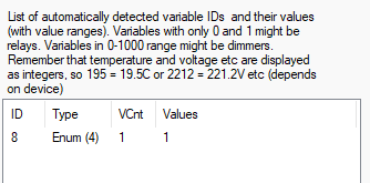
    Screenshot showing a table with ID, Type, VCnt and Values, plus notes about temperature and voltage display

    I have also triggered the water sensor alarm. APP also reports the water overflow.
    Sent by WiFi module:
    55 AA   00   01      00 00      00   
    HEADER   VER=00   Product      LEN      CHK   
    
    Sent by WiFi module:
    55 AA   00   02      00 01   02   04   
    HEADER   VER=00   McuConf      LEN   02   CHK   
    
    Sent by WiFi module:
    55 AA   00   02      00 01   03   05   
    HEADER   VER=00   McuConf      LEN   03   CHK   
    
    Sent by WiFi module:
    55 AA   00   02      00 01   04   06   
    HEADER   VER=00   McuConf      LEN   04   CHK   
    
    Sent by WiFi module:
    55 AA   00   10      00 02   0100   12   
    HEADER   VER=00   ObtainDPcache      LEN         CHK   
    
    Sent by WiFi module:
    55 AA   00   05      00 01   00   05   
    HEADER   VER=00   Unk      LEN         CHK   
    
    Sent by WiFi module:
    55 AA   00   05      00 01   00   05   
    HEADER   VER=00   Unk      LEN         CHK   
    
    Sent by WiFi module:
    55 AA   00   10      00 02   0100   12   
    HEADER   VER=00   ObtainDPcache      LEN         CHK   
    
    Sent by WiFi module:
    55 AA   00   05      00 01   00   05   
    HEADER   VER=00   Unk      LEN         CHK   
    
    Sent by WiFi module:
    55 AA   00   05      00 01   00   05   
    HEADER   VER=00   Unk      LEN         CHK   
    
    Sent by WiFi module:
    55 AA   00   10      00 02   0100   12   
    HEADER   VER=00   ObtainDPcache      LEN         CHK   
    Received by WiFi module:
    55 AA   00   01      00 00      00   
    HEADER   VER=00   Product      LEN      CHK   
    
    Received by WiFi module:
    55 AA   00   02      00 01   04   06   
    HEADER   VER=00   McuConf      LEN   04   CHK   
    
    Received by WiFi module:
    55 AA   00   10      00 02   0100   12   
    HEADER   VER=00   ObtainDPcache      LEN         CHK   
    
    Received by WiFi module:
    55 AA   00   05      00 01   00   05   
    HEADER   VER=00   Unk      LEN         CHK   
    
    Received by WiFi module:
    55 AA   00   05      00 01   00   05   
    HEADER   VER=00   Unk      LEN         CHK   
    
    Received by WiFi module:
    55 AA   00   10      00 02   0100   12   
    HEADER   VER=00   ObtainDPcache      LEN         CHK   
    
    Received by WiFi module:
    55 AA   00   10      00 02   0100   12   
    HEADER   VER=00   ObtainDPcache      LEN         CHK   
    
    Received by WiFi module:
    55 AA   00   05      00 01   00   05   
    HEADER   VER=00   Unk      LEN         CHK   
    
    Received by WiFi module:
    55 AA   00   05      00 01   00   05   
    HEADER   VER=00   Unk      LEN         CHK   
    
    Received by WiFi module:
    55 AA   00   10      00 02   0100   12   
    HEADER   VER=00   ObtainDPcache      LEN         CHK   
    
    Received by WiFi module:
    55 AA   00   05      00 01   00   05   
    HEADER   VER=00   Unk      LEN         CHK   
    
    Received by WiFi module:
    55 AA   00   05      00 01   00   05   
    HEADER   VER=00   Unk      LEN         CHK   
    
    Received by WiFi module:
    55 AA   00   10      00 02   0100   12   
    HEADER   VER=00   ObtainDPcache      LEN         CHK

FAQ

TL;DR: If you flashed an Ambiano SWW04U with a CBU BK7231N, start with 9600 baud sniffing and keep the UART link intact for analysis. As the expert put it, "you can't disconnect the RX-TX lines" when testing TuyaMCU traffic. This FAQ helps leak-sensor owners decide whether the device uses TuyaMCU and whether contact or deep-sleep behavior comes from datapoints or direct GPIOs. [#21902733]

Why it matters: Battery leak sensors can look like simple GPIO devices, but this thread shows that UART protocol behavior, resistor state, and power method change what you can actually detect.

Option RX1/TX1 resistors Main goal Expected result
TuyaMCU sniffing Left in place Monitor serial traffic Valid 55 AA exchanges and DP clues
OpenBeken flashing Removed Isolate Wi-Fi module UART Reliable firmware upload
Sniffing with resistors removed Removed Monitor traffic Broken communication or repetitive packets

Key insight: Do not choose GPIOs for contact and deep sleep until you prove whether the sensor reports state through TuyaMCU. In this thread, meaningful evidence appeared only after correct power and intact UART monitoring.

Quick Facts

  • The extracted Tuya configuration shows a 2 MB original backup, baud 9600, software version 2.1.8, and protocol version fields 2.2 and 3.4. [#21893336]
  • Flashing the CBU required removing R27 and R28 on this board, but that hardware change was tied to firmware upload, not UART sniffing. [#21891113]
  • The first useful monitored exchange appeared only after powering the sensor from its AAA battery while leaving only TX1 and RX1 connected for observation. [#21904788]
  • A decoded UART packet exposed dpId=8, type Enum, value 1, giving a concrete datapoint candidate for later OpenBeken mapping. [#21904788]

How do I determine the correct GPIOs and OpenBeken settings for the contact input and deep sleep on an Ambiano SWW04U with a CBU BK7231N module?

First determine whether the sensor uses TuyaMCU, because direct GPIO mapping is premature if state arrives over UART. In this thread, the practical path was to inspect the PCB, save the original firmware, and sniff serial traffic at 9600 baud before assigning OpenBeken roles. Only after traffic revealed a datapoint like dpId=8 Enum V=1 did the sensor expose a usable clue for contact behavior. Deep-sleep wiring was not identified in the posts, so no thread-backed GPIO number can be claimed yet. [#21904788]

What is TuyaMCU, and how can I tell whether my Ambiano SWW04U water sensor uses it?

"TuyaMCU" is a serial control interface that links the main MCU and the Wi-Fi module, uses the same UART as flashing, and carries device-state messages instead of raw GPIO changes. You can suspect it when the original firmware shows UART settings such as 9600 baud and when sniffing reveals repeated 55 AA framed packets like Product, McuConf, or ObtainDPcache. That is exactly why the expert first asked to verify TuyaMCU support before mapping GPIOs. [#21891774]

How do I use TuyaMCUAnalyzer with a USB-to-UART adapter to sniff communication on a BK7231N-based Tuya device?

Use the analyzer as a listener, not as a line breaker. 1. Keep RX1 and TX1 connected through the board so the MCU and Wi-Fi module still talk. 2. Attach the USB-to-UART adapter to monitor the same UART at 9600 baud. 3. Power the sensor normally and trigger events, then watch for 55 AA frames and datapoints. The expert explicitly recommended a USB-to-UART intercept and linked TuyaMCUAnalyzer for this purpose. [#21894259]

When flashing OpenBeken on a CBU BK7231N, what's the difference between removing the RX1/TX1 resistors and leaving them in place?

Removing the RX1/TX1 resistors isolates the Wi-Fi module for flashing, while leaving them in place preserves live MCU-to-Wi-Fi communication for analysis. The thread states that both operations share the same UART, so the TuyaMCU can interfere with firmware upload. That is why resistor removal is a flashing step, not a monitoring step. If flashing already works with the resistors installed, the expert said you do not need to remove them. [#21897286]

Why do I only see repeated 55 AA 00 01 00 00 00 packets in TuyaMCUAnalyzer instead of useful data?

You usually see that repetitive frame because the UART path or powering method is wrong for live monitoring. In the thread, the sensor first showed only 55 AA 00 01 00 00 00 and little else when the setup was incorrect, then produced richer traffic after correct battery power and intact monitoring. Another failure mode is disconnecting RX and TX during analysis, which breaks the conversation you are trying to capture. [#21904788]

What can I learn from a backup of the original Tuya firmware before pairing, and how does it help identify device configuration?

A pre-pairing backup can reveal the device's stored Tuya configuration and UART parameters without exposing your own Wi-Fi credentials. In this case, the extracted config showed baud 9600, software version 2.1.8, bv 40.00, pv 2.2, lpv 3.4, and several gateway fields. Those values help confirm that the original firmware expects serial communication and give you a baseline before replacing it with OpenBeken. [#21893336]

How should I power the Ambiano SWW04U during UART monitoring so TuyaMCU traffic appears correctly?

Power it the same way the sensor normally runs, which in this thread meant the AAA battery. The user reported that meaningful traffic appeared only after using the battery supply and leaving only TX1 and RX1 connected for monitoring. Before that change, the UART capture was sparse and misleading. Normal operating power matters because the board has to boot and communicate exactly as it does in service. [#21904788]

What does the Tuya serial message "ObtainDPcache" mean, and how should I interpret packets like dpId=8 Enum V=1?

In this thread, ObtainDPcache is the UART message that exposed cached datapoint information rather than a direct GPIO number. The useful decoded example was a frame with dpId=8, type Enum, value 1, which gives you a concrete software-level signal to map later in OpenBeken. Treat that packet as evidence that the sensor state may be reported through Tuya datapoints instead of a simple contact pin. [#21904788]

Why might TuyaMCU communication look one-sided or incomplete after removing and reinstalling RX/TX resistors on a sensor board?

One-sided traffic can mean the UART path is still damaged after rework. The expert warned that if communication is not working on the factory firmware, one of the lines may remain interrupted, for example by a cold solder joint. That fits boards where resistors were removed and reinstalled around RX1 and TX1. In practice, incomplete logs after solder work point to hardware continuity before they point to protocol problems. [#21903038]

What is the "McuConf" message in Tuya UART logs, and what does it reveal about the device setup?

McuConf is a configuration exchange between the MCU and the Wi-Fi module, and its presence confirms active serial negotiation. In the captured logs, McuConf appeared repeatedly with single-byte payloads 02, 03, and 04, framed inside standard 55 AA packets. That does not reveal the final GPIO map by itself, but it proves the device is talking over Tuya UART and not acting as a pure standalone GPIO sensor. [#21904788]

Which steps are best for mapping Tuya data points from a water leak sensor to OpenBeken functions after capturing UART traffic?

Map datapoints before GPIOs when the logs already show Tuya-style messages. 1. Capture stable UART traffic with the original firmware at 9600 baud. 2. Trigger a real leak alarm and note which datapoint changes, such as dpId=8 Enum V=1. 3. Use that event-to-datapoint link as your OpenBeken mapping baseline. This method is stronger than guessing pins from the PCB alone because it ties a real water alarm to a specific serial payload. [#21904788]

How can I tell whether a water alarm event on the Ambiano SWW04U is reported through TuyaMCU datapoints or a direct GPIO state change?

Trigger a real water alarm while monitoring the original firmware and watch whether the UART log changes. In this thread, the user triggered the leak sensor and the app reported overflow, while the monitored conversation showed Tuya-formatted packets including an ObtainDPcache frame carrying dpId=8 Enum V=1. That is direct evidence of datapoint-based reporting. A pure direct-GPIO case would need a proven pin transition, and the thread never identified one. [#21904788]

What are the safest soldering and hardware handling practices when removing resistors like R27 and R28 from a BK7231N device for flashing?

Remove only the parts that isolate the shared UART, document their original positions, and verify continuity after reinstalling them. In this case, the user removed R27 and R28 to flash the CBU, but later troubleshooting showed that bad reconnection can leave UART communication incomplete. The safest rule from the thread is functional: remove resistors for flashing only, and keep the line intact for monitoring. [#21891113]

OpenBeken vs original Tuya firmware on a battery-powered leak sensor: which is better for local control, deep sleep, and battery life?

The thread supports OpenBeken as the path to local control, but it does not provide measured battery-life or deep-sleep results for this sensor. What it does show is that the original Tuya firmware is valuable first because it exposes live UART behavior, datapoints, and baseline configuration such as 9600 baud. Use the factory firmware to learn the device, then switch to OpenBeken once you know whether state comes from TuyaMCU or a direct pin. [#21893336]

How do photos of the PCB and module help identify the contact sensor pin, UART lines, and possible deep-sleep wiring on a CBU BK7231N board?

Photos help by showing the module type, the UART path, and the exact resistors and traces involved in flashing or sniffing. In this thread, the PCB photos led directly to follow-up questions about TuyaMCU support and to the identification of the RX1/TX1 resistor area later used for removal and monitoring. Visual inspection narrows the search space, but the posts still required UART evidence before any contact or deep-sleep pin could be trusted. [#21893303]
Generated by the language model.
ADVERTISEMENT