logo elektroda
logo elektroda
X
logo elektroda

OpenBeken on CB3S/BK7231N: drive unknown 3-wire RGB hex lights via pin 9

ScanuRag 390 11
ADVERTISEMENT
  • #1 21893014
    ScanuRag
    Level 3  
    Posts: 5
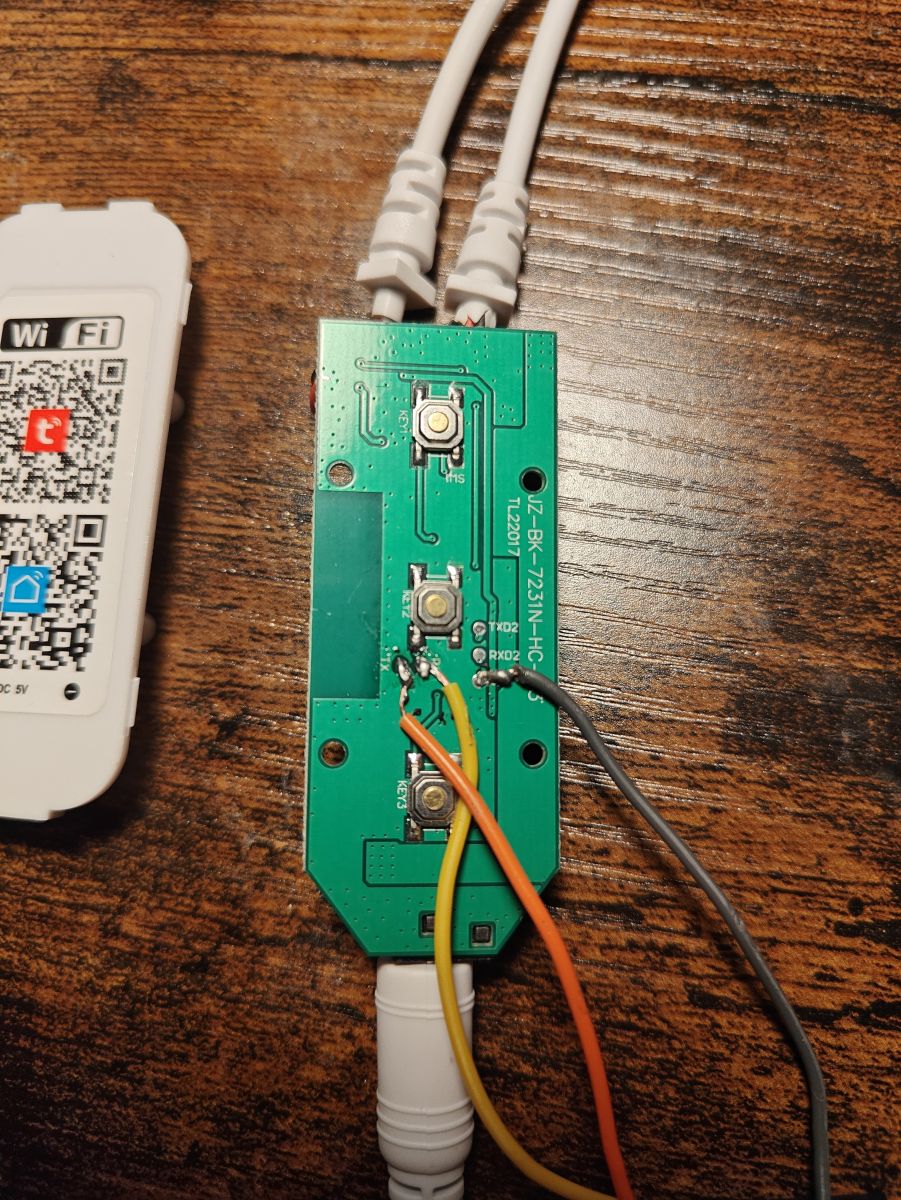
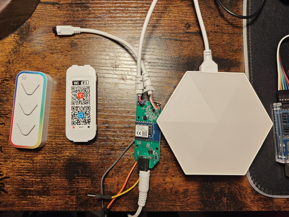
    Green PCB with three push buttons and connected wires on a wooden tabletop Remote with three buttons, a Wi‑Fi QR code module, and a wired circuit board next to a white hexagonal panel

    I've been playing around with a set of RGB hex lights, and am hoping to get local control. The exact brand is unknown, but both the lights and controller look identical to this listing on Amazon. The lights connect to each other and the controller with USB-A connectors, but the actual protocol is an unknown 3-wire addressable RGB protocol.

    I opened up the controller and found a CB3S (BK7231N) module inside, along with test points for RX1/TX1, RX2/TX2, and GND, making it quite easy to flash OpenBeken. I attempted to dump the original firmware, but the process repeatedly failed at 1%, so I guess I'm starting from scratch. So far, I've identified the following connections:

    ItemPin
    RGB Data9
    Power Button14
    Mode Button8
    Music Button7
    IR Receiver26

    Getting the buttons to work was relatively easy, but I've been unable to get the lights to do anything. The hexagon modules seem to be glued together, and I don't think I can get one open to see what chip it uses without destroying it. Additionally, most of the 1-wire RGB drivers in OpenBeken seem to require the use of the SPI, which pin 9 is not capable of. The RGB data wire is connected directly to pin 9 through a 100 ohm resistor. Any ideas on figuring out how to drive the RGB?
    AI: Do you have any scope/logic-analyzer captures from pin 9 while the stock controller is running (for example, when changing color/mode/brightness)? Even a rough timing screenshot would help narrow down whether it’s 1-wire, UART-like, clock/data, etc.
    I unfortunately do not have access to a scope, and even if I did I've already flashed OpenBeken onto the controller so I can't investigate the stock behavior any more.
    AI: Can you confirm what the “3-wire” actually is between the controller and the first hex tile — just VCC/GND/data, or are there separate data/clock lines — and does the original controller still drive the lights normally so you can probe it in a known-good state?
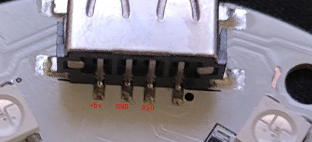
    It is just VCC, GND, and data. I don't know if this is useful, but the data pad on the board is labeled "ASD"
  • ADVERTISEMENT
  • #2 21893126
    divadiow
    Level 38  
    Posts: 4911
    Help: 430
    Rate: 872
    ScanuRag wrote:
    I attempted to dump the original firmware, but the process repeatedly failed at 1%


    :( that's a shame, there may have been clues in the dump and/or boot log. Did you capture factory boot log before flashing OBK?
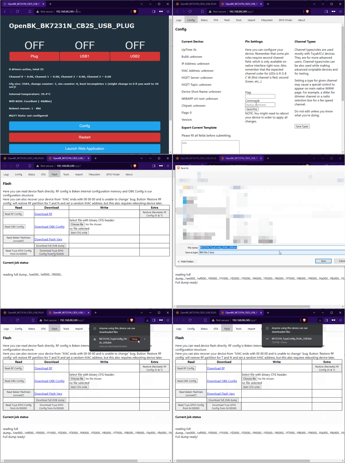
    You could still download the Tuya config partition, if it's present, and run it through Easy Flasher's config extractor.

    OpenBeken on CB3S/BK7231N: drive unknown 3-wire RGB hex lights via pin 9

    please post the enhanced extraction json, redacting any SSID and pasword values that it may contain if it was ever paired with Tuya.

    Any chips in the light bits that may offer clues about the protocol?
  • #3 21893417
    ScanuRag
    Level 3  
    Posts: 5
    I did not manage to get a factory boot log before flashing, but I was able to get the Tuya config data.

    {
    "abi":"0",
    "id":"null",
    "swv":"1.0.0",
    "bv":"40.00",
    "pv":"2.2",
    "lpv":"3.3",
    "pk":"yz3ni9zxsorn79cc",
    "firmk":"null",
    "cadv":"1.0.3",
    "cdv":"1.0.0",
    "dev_swv":"1.0.0",
    "s_id":"null",
    "dtp":"0",
    "sync":"0",
    "attr_num":"0",
    "mst_tp_0":"0",
    "mst_ver_0":"null",
    "mst_tp_1":"0",
    "mst_ver_1":"null",
    "mst_tp_2":"0",
    "mst_ver_2":"null",
    "mst_tp_3":"0",
    "mst_ver_3":"null "
    }

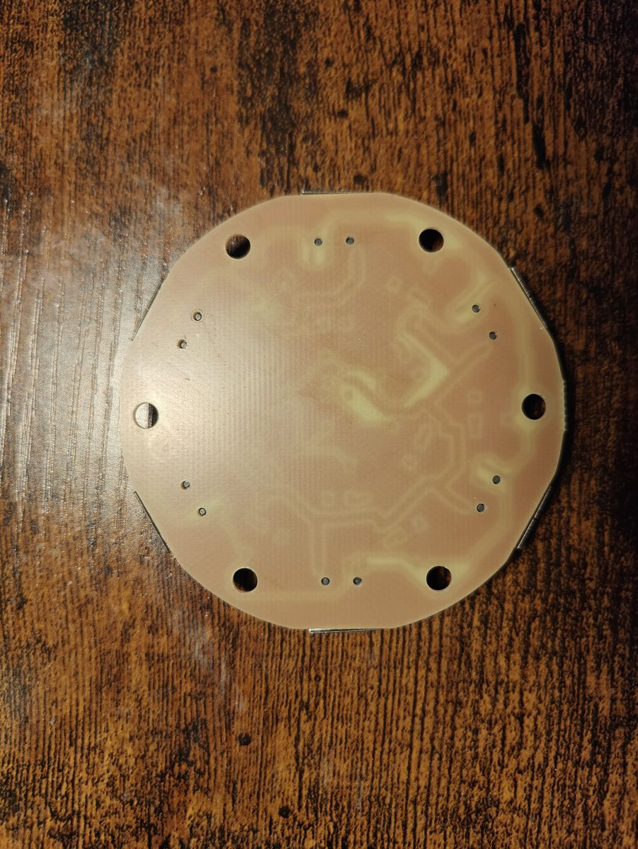
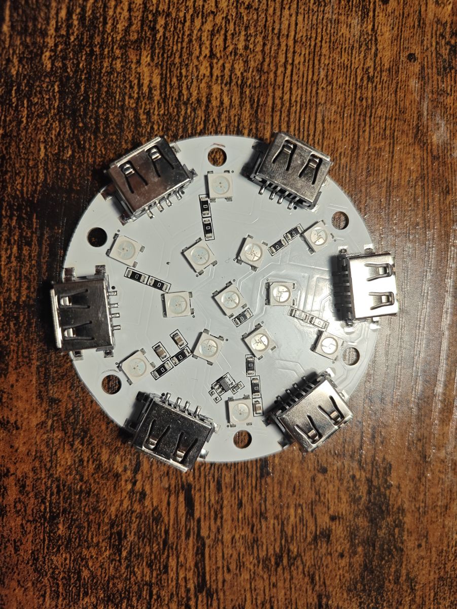
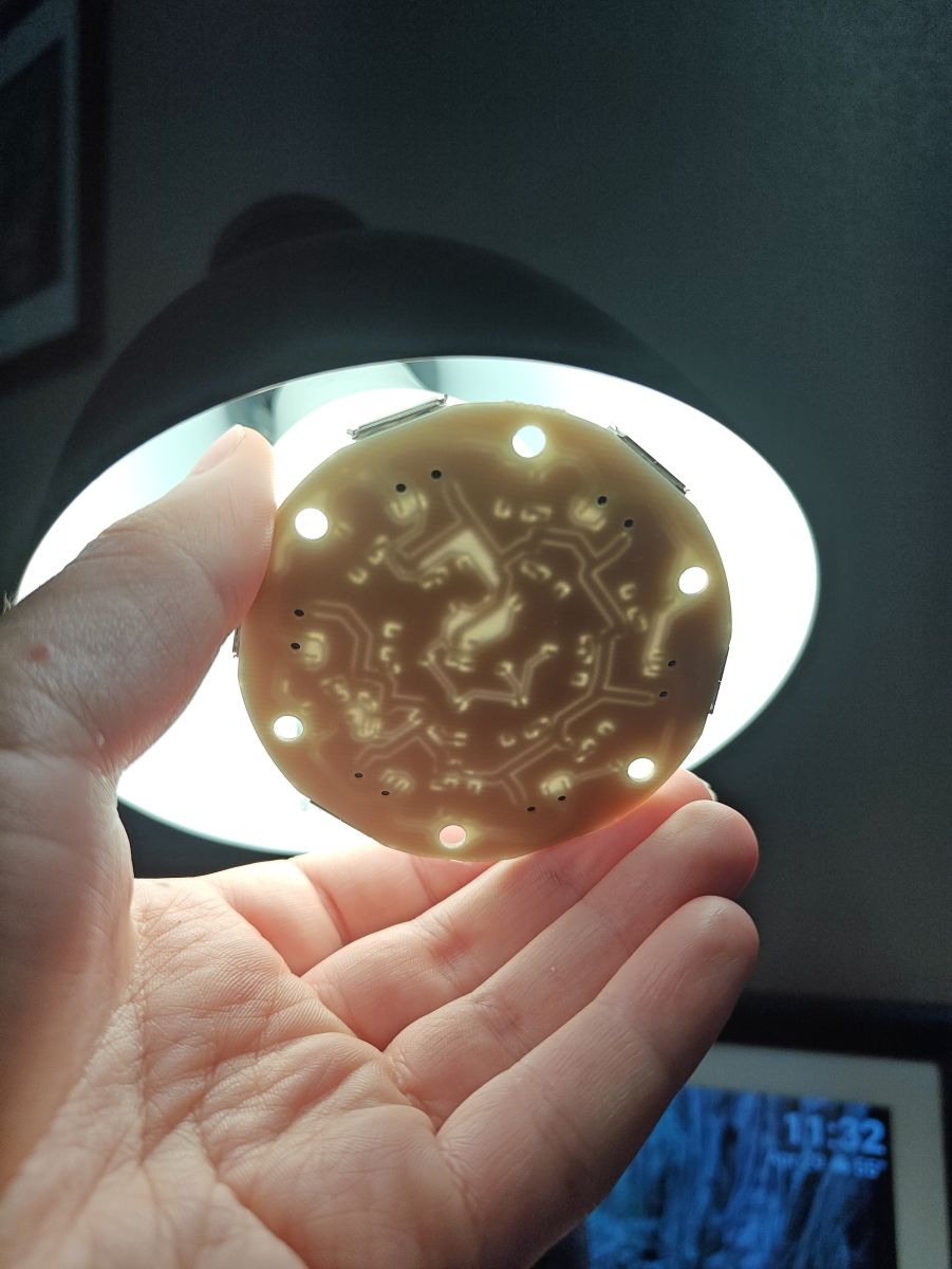
    After applying a lot of isopropyl alcohol to soften the glue, and a bit more force, I did manage to get one of the lights open after all. Inside are 13 LEDs, some miscellaneous surface-mounted components, and a 5-pin IC labeled AC21. Since it was a single-layer PCB, I was also able to shine a light through it to get a better sense of the traces.


    OpenBeken on CB3S/BK7231N: drive unknown 3-wire RGB hex lights via pin 9 OpenBeken on CB3S/BK7231N: drive unknown 3-wire RGB hex lights via pin 9 OpenBeken on CB3S/BK7231N: drive unknown 3-wire RGB hex lights via pin 9
  • ADVERTISEMENT
  • #4 21893599
    divadiow
    Level 38  
    Posts: 4911
    Help: 430
    Rate: 872
    thanks for the Tuya config file. This is the full extraction

    Code: JSON
    Log in, to see the code


    I was after the file in the hope I could doctor another BK7231N dump to pair as your device and then hope it would offer an ota update that would result in us having the original app that your device came with. Sadly no OTA offer, despite what looks like a pairing for the right device.

    so, not sure what now
  • #5 21898052
    ScanuRag
    Level 3  
    Posts: 5
    Close-up of a USB port on a PCB with pins and red labels: +5V, GND, ASD
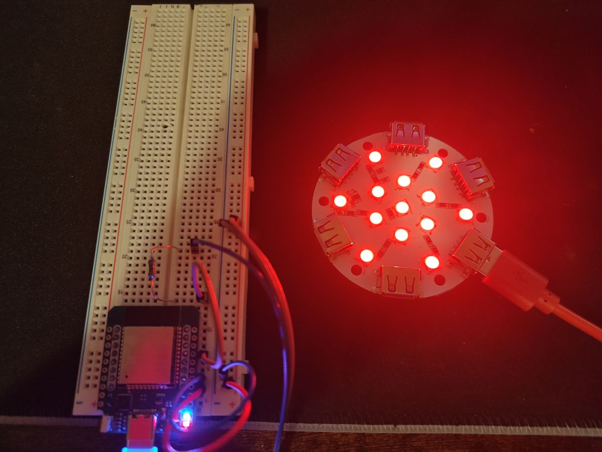
    Breadboard with a microcontroller module and wires next to a round LED board glowing red

    I hooked the panel up to an ESP32, and it worked! I was reading about the various addressable RGB drivers in OBK, and realized that they are almost all hardcoded to use hardware SPI (Pin 16), which is not exposed at all on the CB3S module. I also checked the ESPHome drivers, and the BK7231N ones had the same limitation. Since my board drives the RGB via Pin 9, I figured it wasn't going to work even if my panels used a common chip.

    After hooking it to an ESP32 dev module, I pretty quickly got one of the panels working. Turns out that each panel has a WS2812 clone. The panels run on 5 V power, but the data line seems to be 3.3 V tolerant. Is there any way to get OBK to support these on P9, or am I better off just 3D printing an enclosure for the ESP32 and using that?
  • ADVERTISEMENT
  • #6 21898059
    divadiow
    Level 38  
    Posts: 4911
    Help: 430
    Rate: 872
    interesting! Maybe there was some bit-banging driver thing going on in the factory firmware for this to be made possible on the CB3S. I'm not aware of addressable LEDs being driven on any pin but P16/MOSI on BK7231N before because it's the only one that supports hardware SPI. Maybe @insmod @p.kaczmarek2 agree or have other ideas
  • #7 21898390
    DeDaMrAz
    Level 22  
    Posts: 600
    Help: 34
    Rate: 127
    @ScanuRag

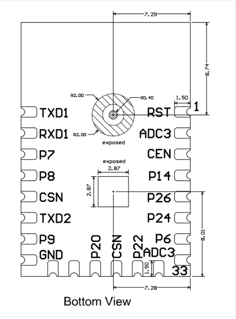
    Can you confirm that data pin is P9 and how many LED does that device control - is it less than 50??


    Technical drawing of an IC package with pin labels and dimensions, bottom view


    thanks
  • #8 21898482
    ScanuRag
    Level 3  
    Posts: 5
    Yes, I can confirm that it used pin 9, and the only thing between the pin and the output is a 100-ohm resistor. Each panel acts as single addressable unit. It came with 6 panels, but the product page says the controller can drive as many as 20.
  • #9 21898487
    DeDaMrAz
    Level 22  
    Posts: 600
    Help: 34
    Rate: 127
    Thank you, that makes sense then. They are using software bit-bang that works reliably up to 20 LED's, up to 50 if doable but problematic.

    OBK can, with the HW mod to CB3S (since it doesn't have P16 exposed), reliably drive 200+ LED's - personally tested on my own setup.

    link to mod - https://www.elektroda.com/rtvforum/topic4005865.html#20790939

    Need to mention that the mode can be tied in to P9 in your case to avoid modifying anything else in circuit.
  • ADVERTISEMENT
  • #10 21898567
    divadiow
    Level 38  
    Posts: 4911
    Help: 430
    Rate: 872
    surely you could whip-up a software bit-bang driver in 5 mins for P9 ;)
  • #11 21898571
    DeDaMrAz
    Level 22  
    Posts: 600
    Help: 34
    Rate: 127
    @divadiow

    You have too high of an opinion of me 😁 jk, no time for it but it can be done with some NOP timing hacks.
  • #12 21902405
    ScanuRag
    Level 3  
    Posts: 5
    I've looked into exposing P16 on the CB3S, but unfortunately, I don't think my soldering skills are quite up to the task. I do have about a dozen of these ESP32 dev modules sitting around, so I think I'm just going to 3D print an enclosure for one of those and call it good. Thanks for the help though!

Topic summary

✨ Discussion about flashing OpenBeken on an unknown set of 3-wire addressable RGB hex lights using a CB3S/BK7231N controller. The controller exposes RX1/TX1, RX2/TX2 and GND test points, making firmware replacement straightforward, but dumping the original firmware failed at 1%, so the setup was rebuilt from scratch. The user identified GPIO mappings for RGB data on pin 9, power button on pin 14, mode button on pin 8, music button on pin 7, and IR receiver on pin 26. After extracting the Tuya configuration partition, the full config JSON was obtained, including UUID, PSK/auth keys, SmartLife AP settings, and factory pin data. One light was opened for inspection, revealing 13 LEDs, a 5-pin IC marked AC21, and a single-layer PCB with trace visibility through the board, but the exact LED protocol remained unknown.
Generated by the language model.

FAQ

TL;DR: For users trying to run 6 to 20 RGB hex panels from a CB3S/BK7231N, the practical answer is: use an ESP32 or expose P16. One expert conclusion was, "They are using software bit-bang," which explains why stock firmware could drive WS2812-style panels from P9 but OpenBeken usually cannot. [#21898487]

Why it matters: This thread shows the difference between what factory firmware can do with custom timing on P9 and what OpenBeken reliably supports on BK7231N today.

Option Wiring change Reliability Practical limit from thread Best fit
Keep CB3S on P9 None Low with current OBK support Approx. 20 panels Reverse-engineering only
Expose P16 on CB3S Fine-pitch hardware mod High 200+ LEDs tested Best OBK path
Replace with ESP32 dev board New enclosure/controller High Worked immediately on one panel Fastest working solution

Key insight: The panels are not using a mysterious 3-wire RGB protocol. They behave like WS2812-clone devices on 5 V power with a single data line, but the stock controller likely uses software-timed output on BK7231N pin P9 instead of OpenBeken’s usual hardware-SPI path. [#21898052]

Quick Facts

  • The controller used a CB3S module with BK7231N, and the RGB data path ran from P9 through a 100-ohm resistor to the panel connector. [#21898482]
  • The button and sensor mapping already identified was Power P14, Mode P8, Music P7, and IR receiver P26, so only LED driving remained unsolved. [#21893014]
  • One opened panel contained 13 LEDs and a 5-pin IC marked AC21, which helped confirm the panel was a self-contained addressable node rather than a simple dumb RGB board. [#21893417]
  • The installed set had 6 panels, while the product page for the kit claimed the controller could drive up to 20. [#21898482]
  • The panels ran on 5 V, yet an ESP32 test showed the data input accepted a 3.3 V signal well enough to light a panel successfully. [#21898052]

How can I drive unknown 3-wire RGB hex lights from a CB3S/BK7231N running OpenBeken when the data line is connected to pin P9 through a 100-ohm resistor?

You usually cannot drive them directly from OpenBeken on P9 unless a software-timed driver is added. The working path in this thread was to test the panels with an ESP32, which proved they behaved like WS2812-clone devices on a single data wire. For reliable OpenBeken control, the thread recommends exposing P16 on the CB3S, because current BK7231N addressable LED support is built around hardware SPI rather than P9 bit-banging. [#21898052]

Why does dumping the original firmware from a CB3S/BK7231N sometimes fail at 1%, and what can I still recover after flashing OpenBeken?

A dump can fail at 1%, and once you flash OpenBeken you lose the easiest way to observe stock LED behavior. You can still recover useful device metadata by reading the Tuya config partition and extracting its JSON. That recovered data included product key fields, version fields such as swv 1.0.0 and cadv 1.0.3, plus pairing information that may help identify the original device family even without the full firmware image. [#21893417]

What is the Tuya config partition on a BK7231N device, and how do I extract it with Easy Flasher to look for device clues?

"Tuya config partition" is a device-configuration storage area that keeps product identity, pairing data, and version fields, separate from the main application firmware. In this case it exposed values such as pk, swv, bv, and Wi‑Fi setup mode, which gave clues after the firmware dump failed. 1. Read the config partition from the BK7231N. 2. Load it into Easy Flasher’s config extractor. 3. Review the JSON and redact any SSID or password fields before sharing it. [#21893126]

How do I identify the protocol used by USB-connected hexagon RGB panels when the cable only has VCC, GND, and one data wire labeled ASD?

Treat it as a single-wire addressable LED link until testing proves otherwise. In this thread, the cable had only VCC, GND, and data, the board silkscreen labeled that pad ASD, and an ESP32 test later confirmed the panel responded like a WS2812 clone. Without a scope, the best clues came from opening a panel, tracing the PCB, and then driving the input from a known-good LED controller platform. [#21898052]

What is software bit-banging for WS2812-style LEDs, and why would a manufacturer use it on BK7231N pin P9 instead of hardware SPI on P16?

"Software bit-banging" is a timing-based control method that generates a digital signal entirely in firmware, using carefully timed GPIO transitions instead of a dedicated peripheral. A manufacturer would use it on P9 because the stock board already routes LED data there through a 100-ohm resistor, even though P16 is the normal hardware-SPI pin. The thread’s expert answer was direct: “They are using software bit-bang” for roughly 20 panels, with 50 possible but problematic. [#21898487]

Which is the better approach for these hex lights: modifying a CB3S to expose P16 for OpenBeken, or replacing the controller with an ESP32 dev board?

Replacing the controller with an ESP32 dev board is the better approach if you want a fast, low-risk result. The ESP32 lit a panel quickly, while exposing P16 on the CB3S requires fine soldering that the user judged too difficult. The CB3S hardware mod is the cleaner OpenBeken path, but the thread ended with the practical decision to 3D-print an enclosure for an ESP32 because several spare dev boards were already available. [#21902405]

How can I safely open glued RGB hex light panels to inspect the PCB and controller chip without destroying the enclosure?

Soften the glue first, then separate the housing slowly with controlled force. In this case, applying a lot of isopropyl alcohol to the seam softened the adhesive enough to open one panel successfully. After opening it, shining light through the single-layer PCB made the traces easier to follow, which helped identify the internal layout without fully desoldering the board or breaking the enclosure. [#21893417]

What does finding a 5-pin IC marked AC21 inside a hex light panel suggest about the panel design and LED control method?

It suggests each panel contains its own small control stage and behaves as one addressable node, not as three separate analog RGB channels. The opened panel had 13 LEDs, several small surface-mount parts, and a 5-pin AC21-marked IC on a single-layer PCB. Combined with the later ESP32 test, that points to a panel design that accepts a serial data stream and locally drives the LEDs as a single addressable unit. [#21893417]

How many WS2812 or WS2812-clone panels can a BK7231N reliably control with software bit-banging compared with hardware SPI in OpenBeken?

The thread’s practical limit was about 20 panels with software bit-banging, while hardware-SPI output in OpenBeken was reported as reliable for 200+ LEDs. One expert added that 50 LEDs might be possible with bit-banging but becomes problematic. That gap explains why factory firmware could handle the stock setup on P9, yet OpenBeken prefers P16 for stable addressable LED control at larger counts. [#21898487]

Why do most OpenBeken and ESPHome addressable RGB drivers on BK7231N require hardware SPI on pin P16, and what breaks when the controller uses P9 instead?

They require P16 because the BK7231N implementations discussed here are hardcoded around hardware SPI output. When the board routes LED data to P9 instead, those drivers cannot emit the expected waveform on the actual connected pin, so the lights do nothing even if the panel uses a common WS2812-style protocol. That exact mismatch blocked control here until the user tested the panel with an ESP32 instead. [#21898052]

How do I confirm whether each RGB hex panel is a single addressable unit or contains individually addressable LEDs?

Drive one panel from a known working controller and observe whether the whole tile changes as one object. In this thread, the user confirmed that each panel acted as a single addressable unit, not as 13 individually addressable pixels. The installed kit had 6 panels, and the controller specification claimed support for up to 20, which fits a chain of panel-level nodes rather than a long per-LED address map. [#21898482]

What is a CB3S module, and how is it related to the BK7231N in Tuya-based RGB light controllers?

"CB3S" is a Wi‑Fi module form factor that carries the BK7231N SoC and provides the programmable GPIO, UART, and wireless functions used by many Tuya-derived controllers. In this thread, opening the controller revealed a CB3S inside, plus accessible RX1/TX1, RX2/TX2, and GND test points, which made OpenBeken flashing straightforward even before the LED protocol was understood. [#21893014]

How can I test whether 5 V WS2812-clone panels will accept a 3.3 V data signal from an ESP32 or BK7231N without a level shifter?

Connect one panel first and test with a known-good controller at 5 V power and 3.3 V data. That is what worked here: the panel powered from 5 V and responded correctly to an ESP32 dev module, showing the data input was tolerant enough for practical use. Test only one panel before scaling up, because this thread confirms success on a panel-level trial, not a full 20-panel stress test. [#21898052]

What hardware mod is needed to expose P16 on a CB3S for reliable OpenBeken LED output, and how difficult is the soldering work?

You need a CB3S hardware mod that breaks out P16, because that pin is not exposed on the module in its stock form. The thread states this mod can then be tied into the existing P9 circuit so you avoid broader board changes. The trade-off is difficulty: the user inspected the mod path and decided the soldering work exceeded their comfort level, choosing an ESP32 instead. [#21898487]

If I already flashed OpenBeken and lost the stock firmware behavior, what troubleshooting steps can still help me reverse-engineer and control the original RGB hex lights?

You can still recover enough clues to identify the LED method and choose a replacement control path. 1. Extract the Tuya config JSON and inspect product and version fields. 2. Open one glued panel carefully and inspect the PCB, chip markings, and trace routing. 3. Test a panel with a known controller such as an ESP32 to verify protocol assumptions. That sequence turned an “unknown 3-wire” light into a confirmed WS2812-clone panel running on 5 V with one data line. [#21898052]
Generated by the language model.
ADVERTISEMENT