The electronic fuse eliminates the need to replace the element that burns out with excessive current when using a classic fuse, e.g. a fuse. This element does not act as a current limiter in any way - when it rises above the set limit, the system disconnects the circuit. The limiter would instead limit the flowing current to a predetermined limit and reduce the voltage, for example, to preserve the current, or otherwise dissipate excess power, turning it into heat, for example.
The diagram of a simple electronic fuse dedicated to direct voltage presented here consists of two transistors. The circuit consists of one bipolar PNP transistor and a P-channel field effect transistor. The circuit operates in DC circuits on the 'high' side of the power supply, ie connected between the power supply and the receiver, which is further connected to ground.
Transistor Q1 monitors the voltage across resistor R1 plugged into the power line. As the voltage drop across the resistor increases, Q1 becomes conductive. This, in turn, will cause a voltage increase at the gate of the transistor M1, which will cause the transistor to go into a blocked state - the current will stop flowing through it.
After disconnecting the transistor M1, the output voltage will be lower than the emitter voltage Q1, then the resistor R3 starts to conduct, which causes a further increase in voltage on the basis of Q1 and full switching on of the transistor, which will translate into a full disconnection of the transistor M1. The circuit will strike in such a state, the transistor M1 remains disconnected until the user manually disconnects the current from the circuit (in the simulation it was returned with the SReset button).
As the M1 transistor, you can use virtually any MOSFET with a P-channel, which has a sufficiently high operating voltage and low channel resistance in the conduction state (so-called [tex] R_ {DS (ON} [\ tex] - resistance between the drain and the source in a state of conduct).
If the voltage is below 10 V, we can use a MOSFET adapted to logical levels - the resistance of such an element is specified for a gate-source voltage of -5 V or less (see the catalog card). If the supply voltage in the system is higher than the maximum gate-source voltage of the used field effect transistor (typically about 20 V), it may be necessary to limit the voltage on the gate of this element with the use of additional elements - the simplest way to use a normal resistor between the source and the gate, which it will act as a voltage divider that will reduce the voltage at the gate of the FET to an acceptable level.
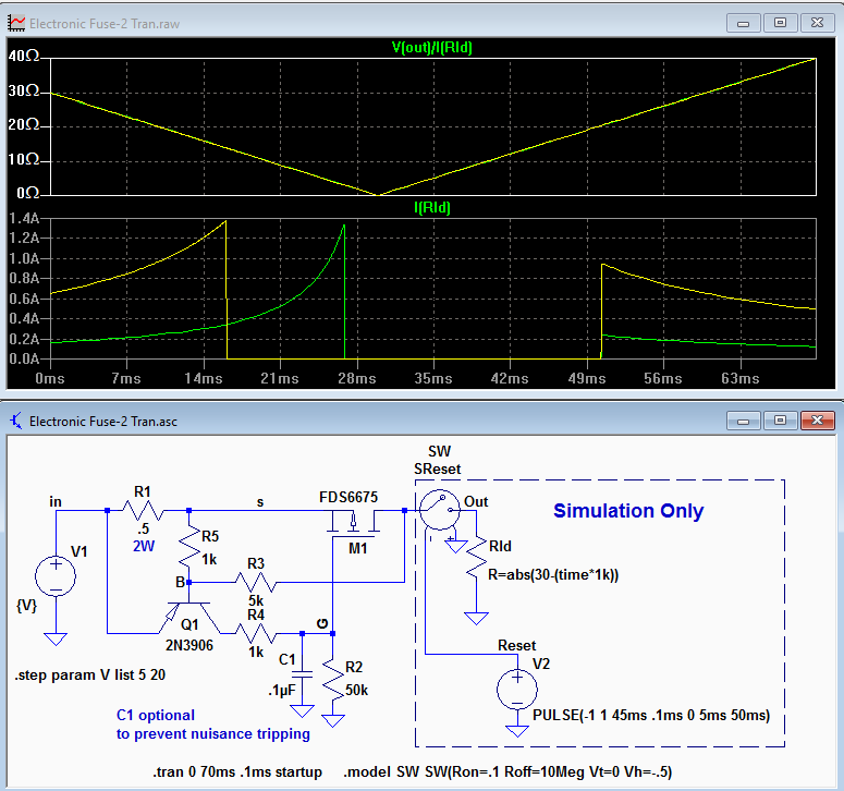
The capacitor C1 is an additional element that extends the response time of the system, thanks to which our fuse will operate with a certain delay, which will ensure that the fuse will not disconnect the system, e.g. when starting the load, when it temporarily consumes more than the maximum current, or in the case of overvoltages and instantaneous increase in current under other conditions.
The author simulated the operation of the fuse using LTspice. The simulations were carried out for two supply voltages - 5 V (green line) and 20 V (yellow line). The circuit trips at a current of approximately 1.3 A. In the simulation, the output remains disconnected for approximately 48 ms until the circuit is closed with the SReset.
The operating current of the system depends on the resistance of the resistor R1. The operating current of the system is approximately 0.67 V / R1 (in ?

.
Source:
http://www.electro-tech-online.com/articles/e...ic-dc-fuse-simple-two-transistor-circuit.773/

Comments
I press on one question on the keyboard. For what ? [Read more]
This is what polymer fuses are for ... What if one of the system components fails and the system is not disconnected? Fuses do not protect the device itself, but against damage such as fire, so they... [Read more]
Well, you can add a second fuse, e.g. a polymer fuse. Polymer ones are difficult because in the event of a long-term short circuit they will not burn up so quickly and will not disconnect the power supply... [Read more]
Colleagues, do not overdo it - sometimes such a fuse is needed. It is fast - unlike the polymer one, the biggest disadvantage of which is the long cooling time. This one has another disadvantage - inaccuracy... [Read more]
Such fuses also exist as commercial circuits. Recently I tried to use STEF05. The circuit becomes dumb if the current is set below a certain value (there is no information about the minimum Rlim anywhere).... [Read more]
The problem is that this "fuse" can burn out on a short circuit [Read more]
It is strange that no one has noticed this "insignificant detail" before. [Read more]
R1 fuse will make a pufff and after a short circuit :) [Read more]
If the short circuit is, say, 2A, where the fuse should work, then 2 * 2 * 0.5 = 2W - the conclusion that the resistor will not do the poof ... [Read more]
And what is R1? What type? How does puff do? If it explodes so that it metallizes everything around it, then the opening may be moderate at best. I saw typical fuses that exploded so much that at a higher... [Read more]
I changed the scheme a little, reducing the value of the resistor R1 a hundred times, while increasing the voltage. Will this arrangement work well? Can it be reduced somehow? http://obrazki.elektroda.pl/6250146700_1487196052_thumb.jpg... [Read more]
In polymer fuses, as already mentioned, the disadvantage is the activation time, in small SMD cases rather low voltage ranges, the spread between Ihold and Itrip, and sometimes quite a resistance causing... [Read more]
It is important how the element puff does. An element that breaks the circuit even with high voltage and a sharp ramp cannot explode so that it metallizes everything around. He should politely puff and... [Read more]
if a germanium transistor was used for Q1, R1 could be smaller. This is because Ube for Ge is about 0.2V instead of 0.65V for Si. Germanicides are still available at online auctions. [Read more]
But why, if you can otherwise reduce the required voltage drop on R1. By the way, becoming independent from UBE changes with temperature changes. [Read more]