Module
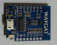
D1 mini compatible with Wemos facilitates the use of a WiFi module
ESP8266-12E incl. thanks to the built-in USB RS-232 converter and the output of signals to connectors with dimensions compatible with the contact plates. ESP8266-12E module complete with relay board
appeared as a gadget available for order on elektroda.pl the module will be ready to work with the Arduino environment. The kit allows you to easily start experimenting with IoT. If you plan to use
D1 mini Shields modules it will be convenient to use female strips, if you want to place the D1 mini on the contact plate, male strips may be more convenient
(three types available in the set) . During installation, it is worth taking care of the lack of metal elements near the printed antenna. Although the system can be powered from USB with 5V, ESP8266 ports work with 3.3V. The micro USB connector allows you to power the system from a USB port or, for example, from a power bank or USB charger.
Arduino environment. The module has been tested with the latest available version of the 1.8.2 environment www.arduino.cc to facilitate work with
https://github.com/esp8266/Arduino run the Arudino environment and choose:
File-> Preferences-> Additional URLs to the tile manager - paste:
http://arduino.esp8266.com/stable/package_esp8266com_index.json next:
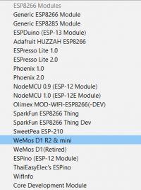
Tools-> Tile-> Tile Manager-> and search for "wemos" and then install the package in Wemos D1 mini with ESP8266:
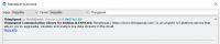
After connecting the D1 mini to the USB port, a new serial port should appear in the system:

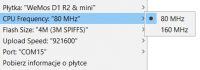
After these treatments, we can select the D1 mini board and indicate the active COM port:
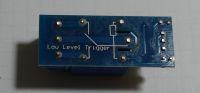
 Relay board.
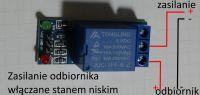
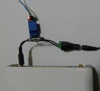
 The relay board requires 5V power supply (relay coil). The attached relay consumes about 60mA. The relay is activated with a low level and the high state of 3.3V of the D1 mini module may be misinterpreted by the relay board (as a low state, in the tested unit, lowering the voltage to 3.5V caused the relay to trip, the relay turned off at about 3.8V). You can redo the board or solve the problem programmatically. With the software solution, to start the relay, set the selected ESP8266 output as the output in the low state, and for switching off the relay as the input in the high pullup state.
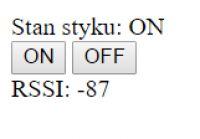
 Controlling the relay via a browser - example.
 Based on the examples available in the Arduino environment for D1 mini, you can easily start trials with the launch of the WEB interface, which will allow you to control the relay via a browser, enter the Wi-Fi login parameters (ssid and password) in the code:
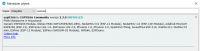
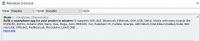
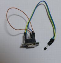
The sample code sends information about the operation of the device using the serial console (USB-RS232) so we know, among others MAC address and IP address of the module. In the final solution, it is worth for the module to have a fixed IP address (e.g. DHCP settings or manual module IP configuration).
By extending the code, we can add, for example, a simple basic WEB authorization, to which the login parameters will be saved in the clear text:
To communicate with the device, all you need is a web browser running on a network segment that supports a Wi-Fi access point to which the ESP8266 module connects.
Some routers do not allow traffic between Wi-Fi clients then you will not be able to access the logged in ESP8266. Thanks to port forwarding on the router, theoretically, you can enable access from the Internet, but even after improving the code, for security reasons, the cloud model will work better here than direct communication.
Cloud solutions. In such a solution, IoT devices connect to the service provider's server by sending information and downloading instructions, wanting to control our devices, we also connect to the service using a browser or an application installed on a smartphone.
Blynk. To use
http://www.blynk.cc in the Arduino environment, choose:
Sketch-> attach library -> manage libraries we search and install the blynk library.
We install the Blynk application on a smartphone, create a new account and a new project, the application is intuitive and "guides you by the hand" through the next steps. We receive a token on the e-mail provided.
We use the example ESP8266_Standalone and enter the login details for our Wi-Fi network and the Blynk token:
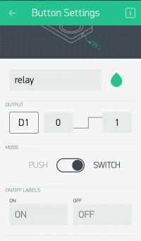
In the new project, we add a button that we assign to the module's D1 output, in Blynk we can easily control more advanced devices (e.g. servos) as well as receive data (e.g. temperature) and set notifications to e-mail twitter or smartphone notifications.
After running the example on the D1 mini board, we will get diagnostic information on the serial console,With the help of an application on a smartphone, we will be able to control the status of the relay from anywhere in the world with access to the Internet.
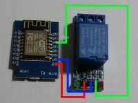
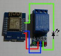
In a simplified way, we will solve the problem with the relay board, which when powered with 5V requires low state control and may cause problems when controlling 0 and 3.3V voltages. In series on the connection of the IN signal and the D1 output of the module, we turn on the LED (with the cathode towards the module), the voltage drop should ensure correct operation (the zener diode with a voltage of ~ 3V should also be checked).
It is best to make a permanent modification on the relay board.
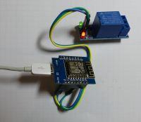
In the video below you can see the variable delay between sending a command and changing the state of the relay.
[movie: 3fb7278bcb]
https://filmy.elektroda.pl/74_1493808196.mp4 [/ movie: 3fb7278bcb]
Supla. You can find a Polish project similar to Blynk here:
https://www.supla.org/pl/ Sending data to thingspeak. Thingspeak is one of the exemplary services that allows you to receive data from IoT devices. After creating an account, we read our API Key, create a new channel and read its ID. We add the ThingSpeak library to the Arduino environment.
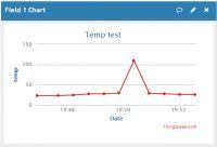
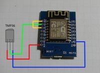
Below is an example code that allows you to send to the created channel temperature data from a sensor with analog output
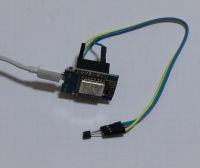
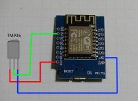
TMP36 .
The sensor is powered from 3.3V (pin 1 of the sensor), pin 3 is connected to GND, and the signal from pin 2 is sent to the analog input of the A0 module. The use of sensors with digital output (eg DS18B20) will allow for easy operation of more sensors by one D1 mini module.
After a while, we can see the history of transmitted data on thingspeak. The device consumes several milliamperes in the breaks between transmissions:
 Energy saving and built-in clock.
 The power consumption of the D1 mini, depending on the program being performed and the constantly set up WiFi connection, can reach even tens of milliamps:
http://bbs.espressif.com/viewtopic.php?t=133 We can put the ESP module to sleep and use the internal clock to give the module reset signal after a certain time. After the reset, the variables in the program will not be saved, but we can achieve quite large energy savings and adjustable long sleep times (e.g. 24h). To use ESP.deepSleep () deep sleep function, pin D0 must be connected to Reset, otherwise RTC will not be able to reset the module:
Sample code below:
It is worth mentioning the possibility of changing the firmware in the ESP, e.g. on the nodemcu or another one:
https://github.com/nodemcu/nodemcu-flasher this can be a good solution to expand the existing device with a WiFi module communicating via UART or an opportunity to get acquainted with LUA.
It is worth getting acquainted with the services that allow the collection, presentation and analysis of data from IoT devices:
https://www.pubnub.com/ https://io.adafruit.com/ http://dweet.io/ http://freeboard.io/ https://data.sparkfun.com/ http://ubidots.com ESP8266 can be used to perform much more complicated tasks than turning the relay on and off, we can, for example, run a single-channel LoRaWAN gateway
https://www.youtube.com/watch?v=ZV_ZY-0Q1lo or send an image from the camera http: // www. arducam.com/arducam-supports-esp8266-arduino-board-wifi-websocket-camera-demo/
What is your idea of using ESP8266? I will use the module in conjunction with blynk for a very simple solution, remotely resetting a VPN sharing router, which can hang sometimes. The D1 mini module has such an effective antenna that it was able to log into the WiFi network of a friend in the same building, thanks to which the module's connectivity with the Internet will be maintained even if the controlled router stops responding.


Comments
Is this an original Wemos module? Because the ones I saw had the manufacturer's logo: http://obrazki.elektroda.pl/2636497900_1494085976.jpg [Read more]
Good question, but I don't know the answer to it, but looking at the documentation on the wemos website, I can see that it is a fully compatible module with the D1 mini. It would be nice if the people... [Read more]
It is a clone that is completely compatible with the Wemos D1 mini. Unfortunately, Wemos withdrew from the D1 mini and focused only on the mini pro. Thanks for paying attention. This is an experiment... [Read more]
In my opinion, this is a great idea, it will definitely encourage users to create projects and post them on the forum. I will wait this month and report on the fun with the module myself ;) But he created... [Read more]
Unfortunately, I lack points to get this module. However, on the ESP-12F itself that I have with AE, I plan to do something like a weather station. The display will be connected (I don't know what... [Read more]
The aforementioned indicator of the current drawn from USB is useful when starting modules such as Wemos, although the accuracy of such a device is not stunning, but as an indicator of what is happening... [Read more]
It depends on what you hit. I have two, one is cheaper and it is indeed inaccurate and has a large voltage drop. On the other hand, the second one, just like the one from the link, is doing very well and... [Read more]
I was not supposed to write, but this tester will be in the shop soon :) There were also USB meters and they will be again. The Raspberry Zero is fun and good value for money, unfortunately you need... [Read more]
Hello, Chicken, I did not even know that the electrode has such a program :D cool thing, out of curiosity whether the electrode also trades such modules, if so, what price :) ? (I know that it is possible... [Read more]
800 points, maybe 700 points as new things appear :) [Read more]
Hmm, we didn't really understand each other because I meant whether the electrode also sells such modules in PLN and not for points :) [Read more]
You have to go to Allegro or aliexpress :) [Read more]
I get it, in short, only for points :) and for posterity it is exactly what version it is, since wemos is not original, I mean the size of flash because the rest probably does not differ ;) [Read more]
And what will we gain after updating this wemos module on nodemcu. Will i2c communication be available then, or will we gain more inputs / outputs. [Read more]
@ rafcio_21 as far as I know, inside the board there is a bootloader (which theoretically cannot be changed) and the correct soft. The 'on arduino' programming method presented in the article... [Read more]
Theoretically, it can not be changed, but somewhere on the net I saw how to win other software, the esp module is the same in wemos as in nodmcu. So theoretically it should be expandable. [Read more]
I have a question for the experts. Do I have to add anything to the code when adding the "button shield" question to the above set (D1 mini + relay shield)? Specifically, I mean control via BLYNK. Will... [Read more]
@ suarez23 do you have a schematic of this button board? I understand that this is about Blynk receiving a button press on the shield? The board with the relay made of material is not the original Wemos... [Read more]
This button and relay and wemos D1 mini come to me from China: button: https://www.aliexpress.com/item/One-Button-Shield-For-WeMos-D1-Mini-Button/32770784800.html?spm=a2g0s.9042311.0.0.It22PT switch:... [Read more]