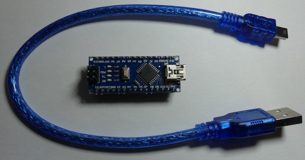
The Arduino nano module equipped with a microcontroller will soon appear on elektroda.pl
ATMega328P clocked with a 16MHz quartz resonator, power supply with 5V from the USB port. The board is equipped with a USB UART converter, which facilitates placing the program from the Arduino environment. On the board, there are LEDs informing about the presence of power, activity on the RX / TX lines of the UART interface and the LED connected to the D13 pin. The microcontroller is powered by 5V and the board ports operate at such logic levels, it should be remembered that some modules tolerate only 0-3.3V on the interfaces. The Arduino nano board also has a 5V stabilizer (power input> 5V on the VIN pin), there is also a reset button. Connector
AND SP allows you to place the program using the programmer, using ISP, you can even opt out of the bootloader or the Arduino environment and send the compiled code written in, for example, Atmel Studio 7.0. Through the ISP connector we can change the microcontroller settings (fusebits). USB UART converter is
CH340 and if there is no driver in the system, they are available on the manufacturer's website:
information about CH340 documentation Windows drivers Linux drivers If the driver is installed correctly, a new serial COM port will appear in the system after connecting the module.
We start the integration with the board by downloading the Arduino environment, the current version is
1.8.4 We create a new program (sketch) and select the Arduino nano board:
Tools-> Board-> Arduino nano
Next:
Tools-> Port-> and select the COM port on which is the board connected to the USB.
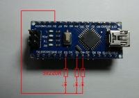
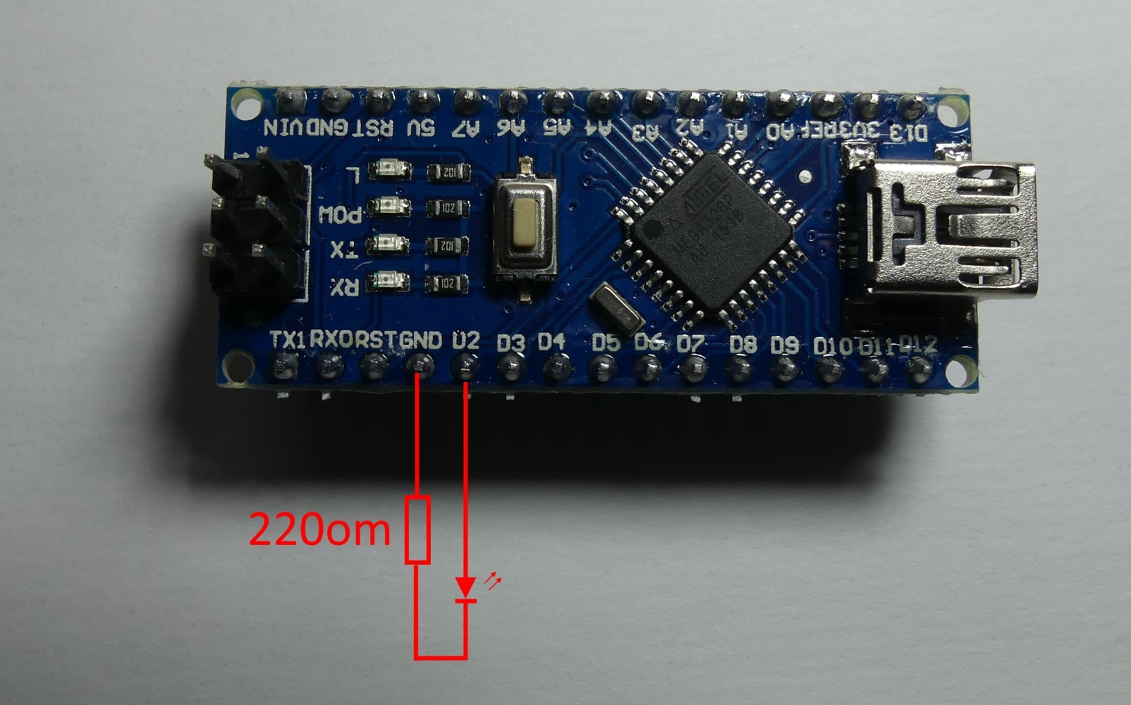
As an example, we will move from the banal LED flashing to controlling the LED to the rhythm of the music. LED flashing. To check if everything is working properly, we will run the program which will flash the LED on the board (D13) and the LED connected with the anode to the D2 terminal, the LED cathode through the 220R resistor to ground (GND) on the contact plate. The LED state can be changed with digitalWrite (pin_number, LOW / HIGH)

We compile and upload the program:
As a result, we have flashing LEDs and the flashing speed can be changed by modifying the delay value:
delay (1000);
[movie: 88fd792b6d]
https://filmy.elektroda.pl/18_1505668055.mp4 [/ movie: 88fd792b6d]
Flashing LED with a change in brightness. To change the brightness of the LED while flashing, we can use PWM with analogWrite (pin_number, value 0-255).
We connect the LED to D3 and through the 220R resistor to ground, compile and upload a simple program:
As a result, we obtain smooth changes in the brightness of the LED light.
[movie: 88fd792b6d]
https://filmy.elektroda.pl/16_1505668363.mp4 [/ movie: 88fd792b6d]
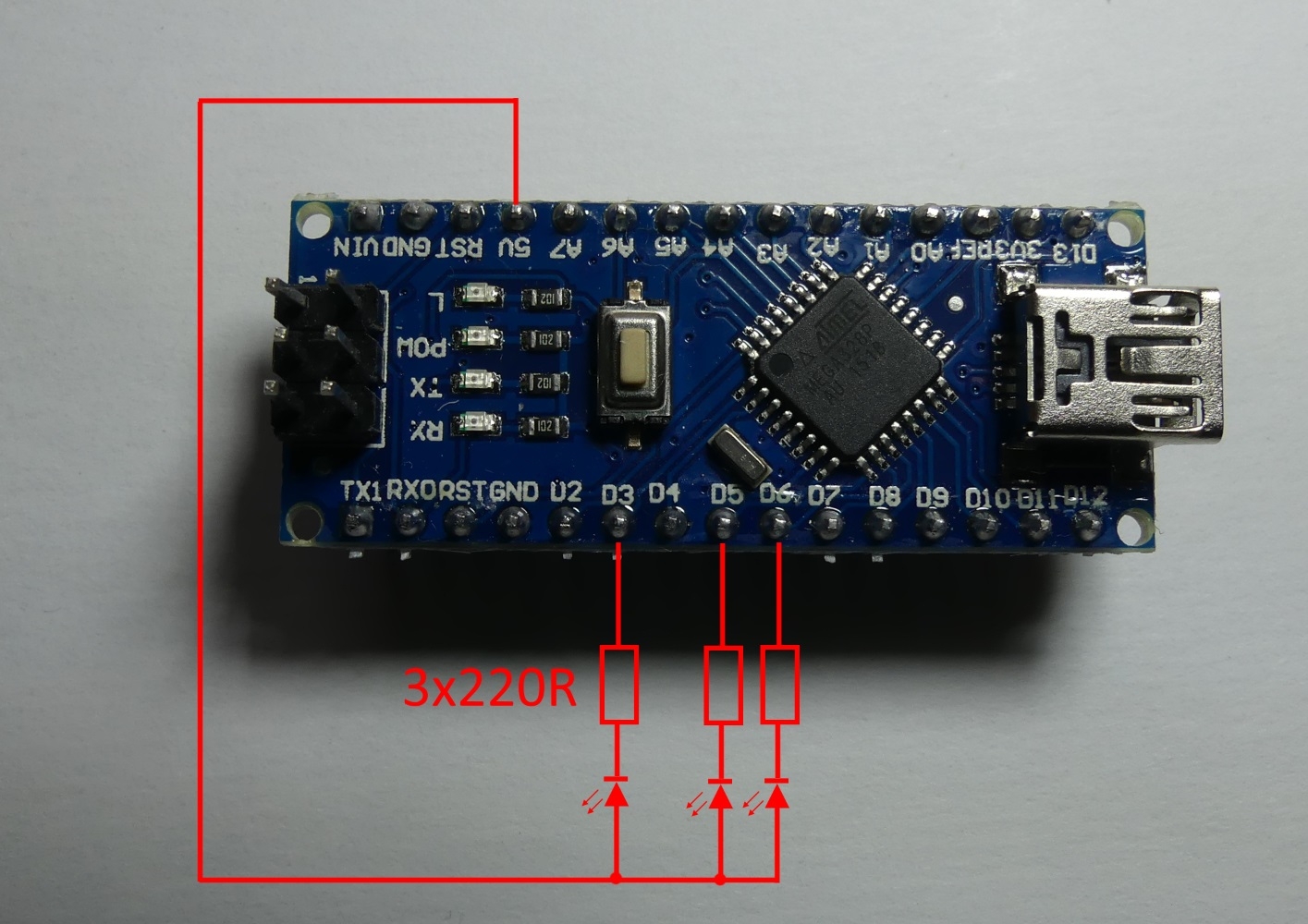
Flashing RGB LED. Connect the LED GRB cathode to D3, D5, D6 through 220R resistors, and the common anode to + 5V and with PWM we can smoothly mix the light colors. As the LED is connected with the anode to + 5V, the PWM 255 filling will mean the LED will go out.
[movie: 88fd792b6d]
https://filmy.elektroda.pl/5_1505668880.mp4 [/ movie: 88fd792b6d]
LED line that reacts to sound. This time, we will connect the LEDs through resistors to GND to the D2, D3, D4, D5, D6, D7, D8, D9 pins and simulate the operation of the LED line responding to the signal given to the A0 input. We will use sample music to test the program:
Link 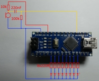
[movie: 88fd792b6d]
https://filmy.elektroda.pl/53_1505669237.mp4 [/ movie: 88fd792b6d]
The miniature Arduino nano module can be useful for many experimental and prototype systems, while numerous examples and libraries will facilitate the implementation of your ideas. Here are two examples of using Arduino to record data on an SD card and in the built-in EEPROM memory:
Weekly measurement of mains voltage frequency - experiment. Heart rate recording while sleeping - Arduino nano. I encourage you to experiment with sample program codes, it can be quite an interesting tool in sound visualization
FFT especially on the ESP8266 or ESP32 platform supporting Arduino and equipped with a faster processor and more RAM, it is worth taking a look at:
FFT in practice using ESP32 and Arduino. Modules with ESP8266 have already appeared in the elektroda.pl gadgets, it is worth checking if they may have appeared again.
What is your idea of using Arduino nano? 


Comments
One more useful information. The board can be powered with voltage up to 15V. As you can see on board we have AMS1117-5.0 which is a 5V LDO stabilizer. The input of this stabilizer is led out to... [Read more]
Hello, AMS1117-5.0 has a power supply up to 15V according to the catalog note. In addition, I downloaded such nano from China for PLN 6.5-7 when buying individual pieces. ($ 1.93 Link . I bought for... [Read more]
Thank you for the hint, I added information about the VIN input that allows powering with> 5V. [Read more]
as I remember correctly, this board should be supplied with Vin 6.5-15V so that this stabilizer gives 5V. [Read more]
I have already corrected my post so that there is no confusion, I confused with the LM1117 which has 20V. As for applications, the Arduino can even be used as a primitive oscilloscope. Project to be... [Read more]
I am going to use the nano in conjunction with the M590 modem to control via sms and additionally sms notification from the ca10 satellite alarm. Currently testing and polishing the code. [Read more]
You can get something better: STM32F103C8T6. Performance and possibilities much more. The price is about PLN 6.50. on Ali, you can program with Arduino IDE. I'm just testing. I ordered 2 pieces. Performance... [Read more]
I have a MySensors node with NRF24L01 + (and HC-SR501 + dimmer of 5050 led strips to implement fade in and fade out to avoid dazzling at night, another node with RGB and MFRC522). On STM32F103, maybe the... [Read more]
@ pawelr98 the effects of thyristor triggering experiments should be put in DIY or articles. @ lukaszd82 it would be good to present the achieved results on STM, good variety from Microchip ARM... [Read more]
@TechEkspert - it is a matter of how to configure, if we want nice hardware PWM then PWM outputs, if we do not mind that sometimes something will not work smoothly, then on any pin you can have software... [Read more]
If I get the contact plate, I will check it. I have an oscilloscope, so the circuit operation documentation will not cause any problems. Ot measuring the voltage from the voltage divider and then calculating... [Read more]
I think the Arduino Pro Mini is a better solution. On Ali for $ 1.45. There are 16MHz 5V and 8MHz 3.3V versions. This Arduino does not have a USB, it can be programmed more conveniently through a converter... [Read more]
@krzbor Arduino mini pro is very good for certain applications, it is easy to get low power consumption (additionally eliminating the LED power), in the 8MHz version it works with 3.3V which allows you... [Read more]
Arduino nano + USB cable appeared in the gadgets elektroda.pl: http://www.elektroda.pl/rtvforum/shop.php [Read more]
One small piece of advice for those who are going to use the ADC built into the board. There are several modes of operation. Default - enter analogReference (DEFAULT) or enter nothing In this mode,... [Read more]
Thanks for the hint, I used analogReference (INTERNAL) in the examples with the microphone signal, the ADC 0-1.1V operating range allowed for greater sensitivity of the circuit, and in the test circuit,... [Read more]
I need something else to program, is the set from the store all that is necessary? [Read more]
The kit includes everything you need. You connect the Arduino to the computer using the included USB cable. Then you install the driver (provided in the first post of this topic). You run the Arduino... [Read more]
With the current version of Arduino 1.8.9, to load the compilation to Nano, select the processor: ATmega328P (OldBootloader). [Read more]