Hello all!
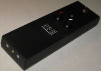
I would like to present a project aimed at practical implementation of the strobe lamp arrangement. Such a lamp is necessary for setting the ignition offset angle in internal combustion engines. I made the device a few years ago and so far it has served me flawlessly.
 Principle of operation:
 The occurrence of the stroboscopic effect can be observed when a given object moves (spins) with the same frequency (or its multiple) as the flashing light that illuminates it. Thanks to the inertia of the human eye, you can see the "stillness" of the rotating element.
This phenomenon is used in many areas, such as automotive, where it is used to precisely adjust the ignition of an internal combustion engine.
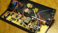
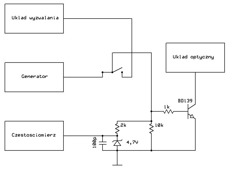
Description of the individual blocks of the device: The light source of the device is a LED type Power LED with a power of one watt, emitting light with an intensity of 38lm. It is placed on a small heat sink because it operates at high currents (up to 300mA) and emits heat. The diode can be triggered by an impulse coming from a spark plug, or by an integrated generator. The block diagram below shows the connection of all device modules. The LED flashing frequency is continuously counted with a frequency counter. To count the frequency at a voltage higher than the target 5V, a simple voltage stabilizer system was used, which reduces the pulse amplitude to 4.7V. The diode is keyed by the BD139 transistor operating in the OE circuit. In order not to exceed its rated current, the system is equipped with a stabilizer with a voltage of about 3.3V, at which the diode consumes a current of about 250mA. As a result of the LED temperature increase during operation, its internal resistance decreases, which increases the current consumed, but the heat sink surface and the LED supply voltage are selected so that the maximum current of 300mA is not exceeded during continuous operation.
Block diagram:  Generator:
 The device uses a generator based on the TL494 chip. The structure includes an oscillator, the operating frequency of which depends on the value of RC elements on pins 5 and 6, and a comparator with emitter followers at the output. It is expanded with many other elements that give additional possibilities, but the designed device does not use any other than the previously mentioned. The principle of operation is typical. At the oscillator output, a sawtooth waveform is directed to the comparator input. The second input of the comparator is influenced by the control voltage (pin no.3). Depending on the value of the control voltage, there is a different actuation threshold of the comparator, the final effect of which is a square-wave output signal with an adjustable duty cycle (PWM). The drive voltage thus determines the pulse length in each period of the square wave output. With the help of resistors it is divided in such a way that the potentiometer changes the filling in the range from 5% to 95%. The frequency of the system can be changed smoothly in the range of 4-100Hz. The structure of the circuit includes a transistor at the comparator output, working as an emitter follower, which controls the BD139 executive transistor. A 1k resistor based on it causes the base current limitation, and 10k polarized one to ground, the other to the power supply plus, discharge parasitic capacitances, so that the waveforms based on the key and output are not distorted. The executive transistor works in a common emitter system. The 1N4007 diode at its output, connected in reverse, and in parallel to the operating LED, has negative pulses generated during the time when the transistor is not conducting.
Schematic diagram of the generator: 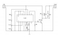 Frequency meter:
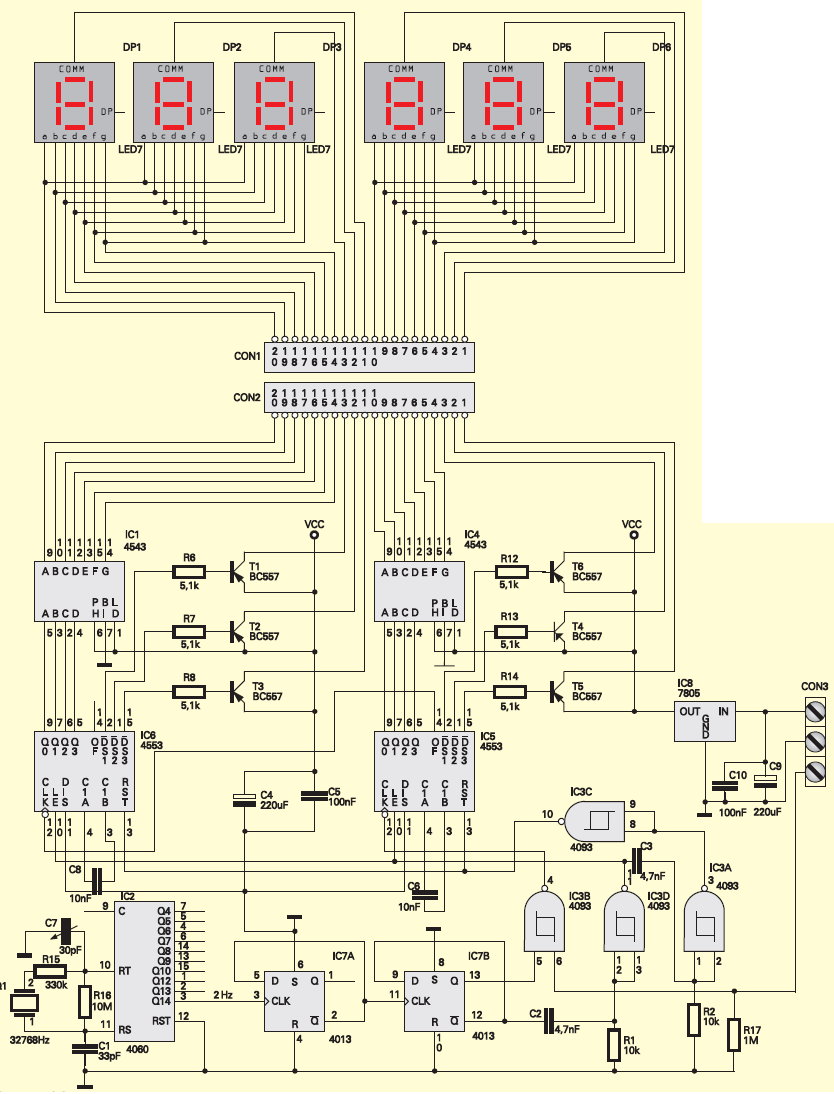
 The frequency meter circuit is based on the AVT-2269 kit with minor modifications. However, half of the system is used, because in the designed device measuring the frequency up to 1kHz it is fully sufficient (3 seven-segment displays). The task of the meter is to count the pulses in a given time unit and display them on the display. The meter is clocked with a quartz-stabilized generator with a frequency of 32.768kHz. This frequency is divided by 214, which gives 2 Hz at its output, and then on the two D-type monostable flip-flops by 4, which gives a waveform with a frequency of 0.5 Hz, in which the low and high states last one second. During the high state, the logic gate is open and the second input is influenced by the measured signal. It is then counted by the counter, snapped with a LATCH latch and displayed on the seven-segment displays that are multiplex-controlled. The entire cycle is repeated every second. The arrangement in practice did not cause any major problems, but it is extremely capricious. It needs a very stable power supply (a small variable component caused incorrect operation), and a supply voltage of 5V, although the integrated circuits used can work up to 15-18V. At a voltage higher than 5V, even by half a volt, the system freezes, stopping the previously indicated value and stays in the latch. The measured signal must also have a strictly defined voltage amplitude (4.2V-5V), therefore, in order to extend the possibilities of measuring signals to 15V, the measured voltage stabilization (peak cut) was applied to the value of 4.7V on the Zener diode. The maximum relative error of the frequency measurement of the system is 0.1% + 1 significant digit. In order to calculate the error, the system was compared with the TCX0-5 reference made according to L-18 / WT-6860-074.
Schematic diagram of the frequency meter: 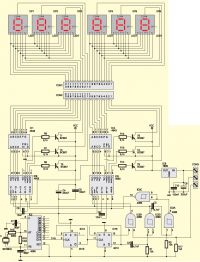 Power system:
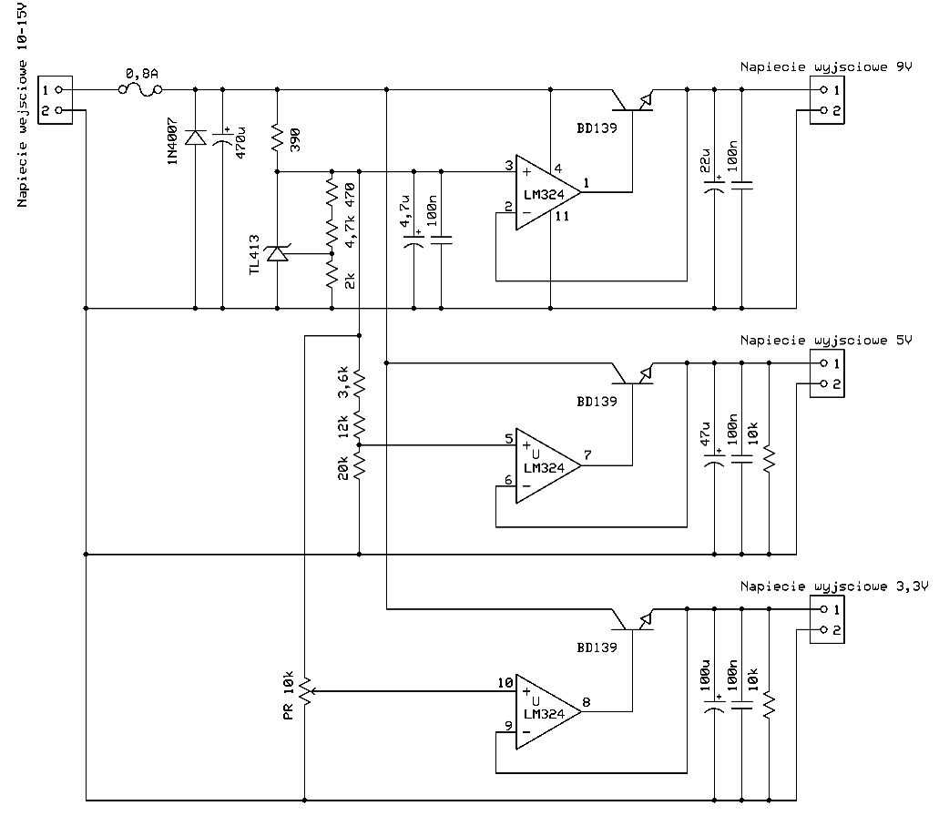
 The power supply provides 9V for the generator, 5V for the frequency meter circuit, and 3.3V for the LED operating diode. The output voltages are very stable. The TL413 chip was used to obtain the reference voltage. Its value is set to 9V and then divided to 5V and 3.3V by voltage dividers. Voltage from 10.5V to 15V can be applied to the input of the power supply for the unchanging parameters of the entire system. The range covers the voltages that may occur in the automotive installation. The reference voltage, after filtering on the capacitors, goes to the positive inputs of the LM324 operational amplifiers. These amplifiers control the output transistors directly, and their negative inputs have output voltages. The operational amplifier always tends to the "virtual zero" between the positive and negative inputs, so all changes in the output voltages are compensated by them, so that the output is always, regardless of the load and temperature, the set voltage with a high accuracy. The additional capacitances filter out the voltage and allow time for the feedback (which is itself very fast) to respond to current pulses. Such pulses are taken by an executive LED diode, so its voltage must be rigid so that there is no fading effect during operation.
Schematic diagram of the power supply: 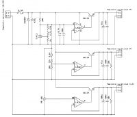


Comments
Sorry, there is something I don't understand. If a colleague wanted to build a non-contact tachometer, it was not easier to shine a laser on a glued reflection on a rotating element and count the reflected... [Read more]
I used to use a simple strobe to set the ignition made of NE555 and a few white LEDs, it was used to set the ignition of mopeds where it was fine and it could be done quite well. The only drawback was... [Read more]
TL494 is probably an exaggeration. You can easily do it on the mentioned NE555 or one of Schmitt's goals. You don't actually see how the TL494 is synchronized. The frequency meter can be done... [Read more]
TL 494 is not synchronized, the measurement is made by using the strobe effect of standing still. You set the LED blinking frequency with the potentiometer until the marker on the flywheel illuminated... [Read more]
3V for Lm at what current? With the same current, how much will BD135 / 9/7 decrease? Probably close to 2V and that means 10-2 = 8V. I'm wrong? And LDO in one case, it was impossible to think (it's... [Read more]
R-MIK you are right, but the microprocessor is wrong. I was quietly hoping he would improve on LDO. And then I will say that the TL494 has an internal V-ref 5V PIN 14 stabilizer, and it can be powered... [Read more]
I don't want to analyze it. I would only use 5V or only 3V3. That's how it starts. But as many as 3 voltages? And nowadays, it's rather a stab. impulse. Here we have LED, powered by 5V, so... [Read more]
Explain to me Joker2 as it is - there are 6 displays on the diagram, and 3 on the PCB - which is true :) ? [Read more]
However, I have already spoken about this project and there is something noteworthy (according to me), the author wrote that: So buddy, before you start writing something, please read all the material,... [Read more]
Buddy, but I am asking the author, not you, and I expect more explanations from the author. If you were reading this carefully and not writing provocative posts, you would know why I'm asking the... [Read more]
Let the author explain to me how to set the ignition in an old gasoline using this strobe ... I can't see the triggering of HV anywhere. [Read more]
It is rather a project like the Chameleon. He got ESP and he has everything in deep respect. These gifts should be given e.g. 7 days after publication. In fact, I will show the seal of salaks and other... [Read more]
A colleague below answered the first and third doubts with his post. As for the second doubt; there is no trigger circuit in the schematic because "The diode can be triggered by an impulse from... [Read more]
Beginner since 2006. I started to reply from the end so my friend is not discouraged, because I do not judge this project so badly., I will write more in a moment. It's a bit like the handful of... [Read more]
I expect so, because then your diagram is wrong and it should be corrected. Where do you see the lack of culture here - if you point it out to me, I'll apologize. [Read more]
Joker2: You didn't understand. The TL494 power supply is from 7V to 40V, so a stabilized 9V source is not needed because you assume the system will work in the range of 10-15V (automotive installation).... [Read more]
I still do not know how to set the ignition in Tico ... Let my colleague the author explain to me how to set the ignition to 17 ° before TDC. The blinking led will give me information about the frequency... [Read more]
You're right. This would simplify the deal. Thank you for the substantive comment and pointing to the error in the diagram (I have already corrected it). You can use a probe like this: http://sklep.gotronik.pl/sonda-wysokiego-napiecia-na-kable-zaplonowe-produkcji-hantek-ht25-p-104.html ... [Read more]
I know how to set the ignition, but I don't think my colleague the author ... The project is called "strobe lamp for setting the ignition offset angle" and this device does not meet this condition.... [Read more]