Hello all.
Below is a brief description of the power supply module for the contact plates at the output, which we have two voltage levels - 5VDC and 3.3VDC.
This module can be found on Polish auction portals under the name "MB102 Breadboard Module" at a price from about PLN 6 with shipment or on Chinese portals as "Breadbord power supply module MB102" at a price from about $ 0.50 with shipment.
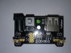
On the PCB of the module, we can find a DC power socket (in my case it is a 5.5x2.1mm socket), where you should provide power not exceeding 15VDC, USB socket, switch, two AMS1117 stabilizers, 1A rectifying diode, LED, several capacitors and pins goldpin and two jumpers.
According to the AMS1117 system catalog note, our stabilizers can give us up to 1A.
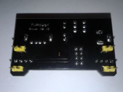
The dimensions of the board are: 53x32x26mm
How is it all connected to each other? Power from the DC socket goes to one half of the double toggle switch. Then, from the switch, it goes through a rectifying diode to a 5V stabilizer in the SOT-223 housing. From the stabilizer it goes to the goldpin pins, the second stabilizer, this time 3.3V, and returns to the second part of the switch. The USB socket is powered from 5V via the switch. The voltage from the 3.3V stabilizer also goes to the goldpin pins.
There are two jumpers on the board - on the left and on the right. The left one is responsible for what appears on the left side of the tile, the right one for what appears on the right side.
The goldpin pins, where we have jumpers, are described as 5V, OFF, 3.3V. Appropriate jumper setting will give us the selected voltage level on the pins under the board, or no voltage, if we put the jumper on the pins marked as OFF.
At the top of the board we have a double-row, 4-pin goldpin strip, where we have a voltage source of 5V and 3.3V, independent of the settings of the jumpers.
As I wrote above - the stabilizers used here can give us up to 1A, but it should be noted that the 3.3V stabilizer is powered from the 5V stabilizer, so we will not take 1A from each of the available voltages.
As the dropout, according to the catalog note, is 1V and we have a rectifying diode in series with the stabilizer at its input, the minimum voltage that we can supply to our module is about 7V.
I was able to get the maximum out of this 350mA module with an artificial load, when there was still 5V on the output, above this consumption the LED used to inform whether our system is turned on starts flashing and the 5V stabilizer starts to heat up.
At first I thought it was a useless gadget, but I started using this board and I have to admit that it is useful - it fits the breadboard and has two basic voltage levels used in electronics. I no longer need to use a lab power supply to power each module. I quickly connect the power supply to this board and I already have a power supply that I can connect with wires to the goldpin pins on other modules or from which I can power the contact plate. It is true that only 350mA is available, but it easily powers small modules.

Comments
Useful thing. I am using the same. As a power source, I have a power supply for a 12V screwdriver - the voltage reaches 15V and has a matching plug. Bought in the shop "around the corner" for PLN 5.99... [Read more]
On one of the well-known auction portals to be caught for 2.99 (gross with invoice). I just bought 5. [Read more]
It is worth adding that these stabilizers do not have any short-circuit protection. Then they are damaged and the full voltage is supplied to the output from the power supply. And it is not difficult to... [Read more]
And the stabilizer manufacturer has a different opinion about security. You have to add how 3.3V and 5V are produced. When using the USB port - 5V is taken straight from the USB, 3.3V is stabilized... [Read more]
A few years ago I gave it 8 zlotys for it :D and I damaged it almost immediately, then the power supply went directly from the power supply as described above. On the other hand, then I didn't know... [Read more]
I use one too. It is a pity that there is no output that allows you to use 12 V straight from the power supply. Alternatively, you can solder to the board yourself or cut the power supply cable and screw... [Read more]
Such module descriptions without a schematic diagram are simply useless. [Read more]
Scheme: https://obrazki.elektroda.pl/1094579900_1517845219_thumb.jpg But can the voltage from USB affect the output U1 [Read more]
The used USB socket is not used to power this module, has been designed as a + 5V power output for other modules. That is why I paid attention to the importance of the diagrams and their comments. This... [Read more]
What is this topic for? [Read more]
Well, probably the test of the said power supply. But I had two of them - some clones and generally never again - the switch I don't know what it was for, but it was of such terrible quality that using... [Read more]
I had two such tiles. The stabilizers are quickly destroyed after an accidental short circuit, and they also heat up mercilessly. Besides, the low price is also the same quality. In my opinion, it is... [Read more]
Today 5 tiles arrived (bought at a well-known auction from a Polish supplier, it is a pity that he did not test them before shipping). One PCB does not work at all (both stabilizers are banged), in the... [Read more]
Not flawed. It does not match with other tiles. [Read more]
. I have the toto and remembered there is a 2.1 x 5.5mm DC power supply socket. I needed 5V from the PSU but I didn't want to cut the DC 2.1 x 5.5mm plug so I thought I'd plug in the PSU and get power... [Read more]
Even LowDrop stab. will not make 5V from 5V :) add two wires to the socket on the board and there will be the desired 5V 2A without cutting the plug. [Read more]