Elektroda.com
Elektroda.com
X

2A DC / DC buck converter test with regulation and voltage and current display

TechEkspert 7914 31
This content has been translated flag-pl » flag-en View the original version here.
  • 2A DC / DC buck converter test with regulation and voltage and current display
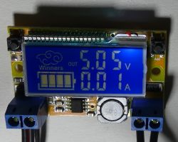
    Soon on elektroda.pl there will be a DC / DC step-down converter module with output voltage adjustment by buttons and output current measurement. Measurements and settings are presented on the backlit LCD display. Maximum input voltage 23V (recommended 20V), output voltage adjustable in the range of 0-16.3V, maximum output current 2A (temporary 3A). The set includes a transparent plexiglass housing. The module has no additional heat sinks beyond the board surface.

    Voltage settings

    Cool? Ranking DIY
    About Author
    TechEkspert
    Editor
    Offline 
    TechEkspert wrote 4622 posts with rating 3759, helped 12 times. Been with us since 2014 year.
  • #2
    szymon122
    Level 38  
    The price and link to the website I would like to ask: p
    What systems is the device assembled on? Do you have a diagram?
  • #3
    bubu1769
    Level 42  
    And what is this battery indicator for?
  • #4
    Adi123xd
    Level 6  
    Please send me the link because I want to buy one myself
  • #5
    mkpl
    Level 37  
    More than 1Vpp of ripple at 5V is a massacre
  • #6
    Krzysztof Kamienski
    Level 43  
    I would like a link to buy, too :?:
  • #7
    fred114
    Level 12  
    Gotronik sells this wonder for PLN 36.
  • #8
    hehehehuhuhu
    Level 19  
    Krzysztof Kamienski wrote:
    I would like a link to buy, too :?:

    Just enter "LCD DC / DC buck 2A plexi case" on ebay.com
  • #9
    Urgon
    Level 38  
    AVE ...

    I have this module but I don't use it anymore. Lack of current limitation disqualifies it in workshop applications. In addition, the factory power connectors suck, I advise you to desolder them and solder the wires directly ...
  • #10
    Szyszkownik Kilkujadek
    Level 37  
    bubu1769 wrote:
    And what is this battery indicator for?

    I join the question. Somebody knows?
  • #11
    czareqpl
    Level 33  
    In my opinion, after watching the oscillograms, this converter is not of good quality.
    With no load, ripple pk-pk 150mV and such pins, the converter probably shines well. I wonder if it meets EMC standards.

    With a load of 1A, the ripple is 1.5V!
    Ripple 1.5V for nominal 5V is 30%. As if to count less restrictively: The regulation level is 15%.

    And then they are surprised that the ADC readings have some weird wave when measuring DC voltage ...
  • #12
    dudik56
    Level 15  
    Szyszkownik Kilkujadek wrote:
    bubu1769 wrote:
    And what is this battery indicator for?

    I join the question. Somebody knows?


    Good for nothing, somewhere I saw a description of "that for future solutions" in advance :D
  • #13
    Szyszkownik Kilkujadek
    Level 37  
    czareqpl wrote:
    Ripple 1.5V for nominal 5V is 30%.
    Defeat.
  • #14
    brofran
    Level 40  
    A few weeks ago, there was also an inverter in GADGETS, but in my opinion it was much better, because it had an output voltage range of 0-30V, and output current adjustment. The only downside was the lack of a display (you can buy one for $ 2). I believe that the previous one was better suited to the needs of amateur electronics.
  • #15
    TechEkspert
    Editor
    @ szymon122 there is no diagram, the modules are e.g. here:
    https://pl.aliexpress.com/item/Diy-kit-DC-DC-...ltmeter-ammeter-Dual-Display/32805760120.html

    I do not know what systems this solution is based on, the display covers everything, but it's a good idea to desolder the module and check how the device is built.

    @ bubu1769 the "battery" indicator hardly serves any purpose, the segments were in the same condition regardless of the operating conditions.

    @mkpl 1Vpp at 5V 1A is a poor result, I am curious if I came across such a module or if all of the series behave like that. Maybe there is a chance to improve the properties of the module?

    @Urgon exceeding the rated current, short circuit at the output causes some smoke effects? Connectors have high resistance? maybe it had an effect on the work of the system?

    @brofran it's about this converter: DC / DC buck 9A 300W 1.2V-35V hopefully it will reappear in gadgets soon, it had quite interesting properties.
  • #16
    Urgon
    Level 38  
    AVE ...

    The connectors are of extremely crap quality, February also did not hurt the ass. After the fourth time the wire fell out, I desoldered these connectors and fired. Now I do not use this power supply, because it is actually low-quality crap ...
  • #17
    krisRaba
    Level 31  
    Maybe some sensible capacitor at the output would help? Just by the eye, after the photos (for spite all from the same angle ;) ), there is nothing specific there except a tiny MLCC. Maybe someone took the executive circuit's catalog note too seriously, where they are usually understated on "marketing pages" and only somewhere further mention that larger ones are recommended? ;)
    If you want to sculpt and there is room, you can add an additional output filter ;)

    When changing to a higher value of the output voltage, the dot jumps and there is only one decimal place? Because the "bajerancka" cloud takes up space and an additional number does not jump there?
  • #18
    sylweksylwina
    Moderator of Computers service
    With such ripples, I do not know what can be powered with it. Probably some kind of heater :P
  • #19
    krisRaba
    Level 31  
    Right out of the box, it's actually a drama. Maybe a matter of looking at what the executive system is and calculating the components. Maybe someone was counting on the knee parameters for a specific output voltage, and for the other end of the range there is a drama. It can probably be improved by changing the choke, capacitor, etc. The only question is whether it makes sense to sculpt it, if there are other, more successful designs ...
  • #20
    nici
    Moderator Chiptuning
    sylweksylwina wrote:
    Probably some kind of heater

    Or a light bulb.

    I powered a raspberry pi of a similar construction with a converter (only without LCD, also ali).
    I was surprised, despite the 5A's performance, Rpi was able to freeze or project lightning in the corner of the screen.

    Perhaps, after modification of filtration, etc., better parameters could be obtained from it, but it should be concluded from the diagram.
  • #21
    mkpl
    Level 37  
    First of all, the output capacitor. A real capacitor, not some SMD x7r, which at nominal voltage has half its capacity. I suggest giving 470uF NXH as the output and it should be much better. A larger capacitor may be needed but this is only due to the ripple current (so that it does not boil over).

    I would leave the choke because there are always problems with that. A larger one will reduce power to improve ripple, and a smaller one will increase ripple and available power (if counted).

    Someone post more information, such as bone actuators or a simple diagram of the power path itself.

    The device seems to be dedicated to solar panels and battery charging. I say right away that he is not suitable for this. If only the battery was charged, then ok, but with a parallel load, the system will generate microcycles on the battery and kill it slowly.
  • #22
    TechEkspert
    Editor
    I did the second round of testing: https://www.elektroda.pl/rtvforum/topic3445958.html
    and checked what elements were used to build the module.

    By accident I managed to change / correct the parameters of the module, it's not bad, but I don't trust this module entirely :)
    the problem is probably the quality of the assembly and possibly the elements used. I wonder if all modules behave identically or I came across one with weaker parameters.
  • #23
    mkpl
    Level 37  
    Well, we already know everything. Popular "mini360" 23V max and 3A power supply. 320kHz operation and the STM processor supports the display and, using a digital-to-analog converter, "adds" voltage to the feedback. At the output, the dice manufacturer recommends 2x 22uF 1206 but at 3v3. These capacitors are bad and with the voltage they lose capacity, hence ripple. Adding a capacitor to the output as I wrote, i.e. 470uF NXH, will significantly improve the parameters of the system.

    I also advise you not to exceed the 20V supply.
  • #25
    Urgon
    Level 38  
    AVE ...

    If anyone is interested, I have put my inverter and power supply for sale - link to my items in the caption ...
  • #26
    wieswas
    Level 34  
    Since there is no schematic for this converter, I would like to ask if anyone tested or analyzed the schematic how it would behave in the unloaded state with the output voltage set to 15V when the input voltage disappeared?
    Is it a forbidden state? Does he have any protection against such a situation?
    After all, the 47uF output capacitor is charged to 15V.
    Is her schematic available somewhere?
  • #27
    nici
    Moderator Chiptuning
    Urgon wrote:
    AVE ...
    what are you with this AVE?
  • #28
    TechEkspert
    Editor
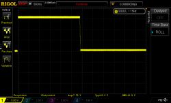
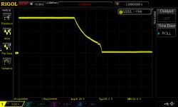
    @wieswas I checked what the output voltage looks like at Vin = 20V Vout = 15V and sudden loss of the input voltage, and the input voltage.
    It looks pretty good.
    2A DC / DC buck converter test with regulation and voltage and current display 2A DC / DC buck converter test with regulation and voltage and current display
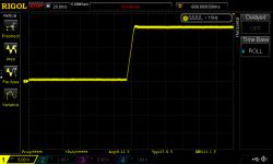
    And voltage supply:
    2A DC / DC buck converter test with regulation and voltage and current display
  • #29
    wieswas
    Level 34  
    Many thanks to "TechEXpert" for this measurement.
    It shows the voltage waveform at the output after the input voltage decay. Hence the conclusion that the voltage system withstands such a state.
    It would also be interesting what about the discharge current if we significantly increase the output capacitors from 47uF to 4700uF to suppress the interference pins.
    (I do not urge anyone to do such an experiment, as it could destroy the system)
    Even more dangerous would be an experiment with a car battery turned on at the exit. Since the capacitor discharges quickly, it means that in the absence of input power, current flows through the converter components from the output to ground. Therefore, the current should be drawn from the output through a diode connected in series, followed by a large capacitor or battery.
    Under load, the voltage behind the diode will be slightly lower than the display indicates.
    The loads will not be the same. It cannot be properly calibrated in any way. I see another danger from the presence of large output capacitors: high current when turned on when charging such a capacitor. The solution would be a current limiter to 2A, but MOSFET + 0.1? measuring resistor will reduce the output voltage by another 0.4V.
    Maybe someone has already tried the layout:
    - external limiter of the maximum load current 2A
    - or by interfering with the converter system
    PS I am currently waiting for the package so I am analyzing the system only theoretically.
  • #30
    krisRaba
    Level 31  
    Theoretically, in the event of a power failure at the input, nothing should happen, because this is a normal operating state, when, for example, you decide to turn off the device with a switch on the input, so I don't know what the concerns are.
    If it's a typical buck, it has a transistor in the power path, in these times it will be a mosfet on the bank. If so, it has a diode in the structure that will transfer the output voltage to the input (taking into account the diode drop). Until the whole thing goes below the UVLO, the converter works almost as normal, only the falling voltage will force it to a large fill ... except that we have more at the output than at the input, so this keying will do little more than reducing the drop on the diode with the open channel of the transistor .
    It would be more interesting to plot VIN against VOUT in this case. Because they are feeling, the VIN should follow the VOUT, once with a decrease in the diode, and once without, due to the open transistor.