As I received a few converters to test and describe on the forum, I decided to start with describing the artificial load made in China, which I often use and I will also use it for the above mentioned. tests. I suspect that, as in the case of the tester, where half of the questions concerned the oscilloscope, also in this case, certainly many readers will have questions about the load used. So I anticipate the facts and start the series of articles with a description, just an artificial load made in China.
I bought this version:
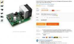
In Aliexpress, enter "Constant Current Electronic Load".
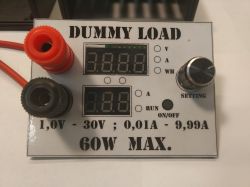
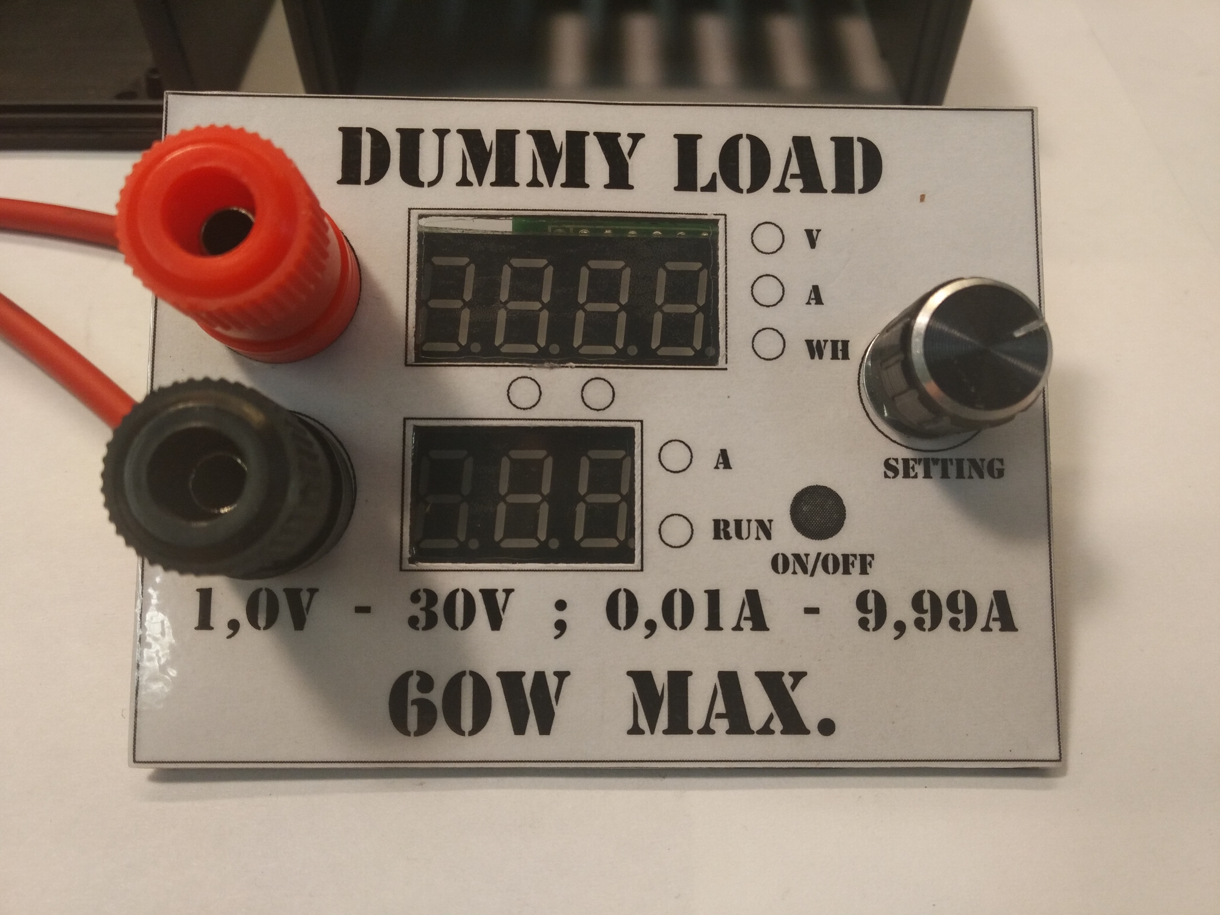
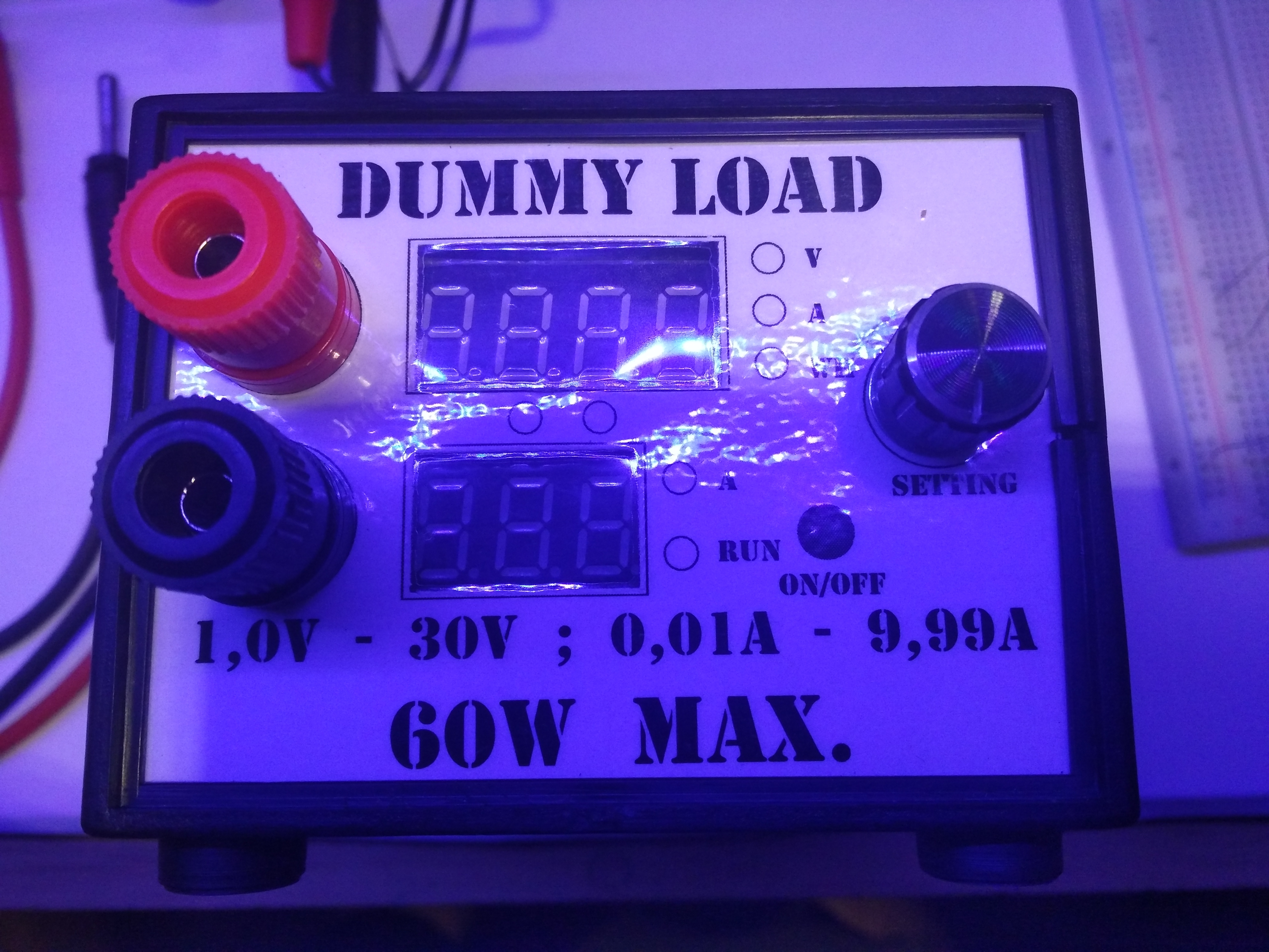
The parameters as you can see are:
- voltage adjustable in the range of 1.0V - 30V
- current adjustable from 0.01A to 9.99A
However, remember that we cannot exceed the maximum power of 60W.
For example, with an input voltage of 12V, we can set the load current to 5A, but with 24V input, the maximum current may be as low as 2.5A.
The system requires 12V 1A to work.
Although I like acrylic transparent housings, in this case I did not choose one. Firstly because of the price.

Second, I find it impractical. The "lying" displays are hardly legible or not visible at all. In addition, in a device of this type, decent clamps are useful, e.g. laboratory banana ones.
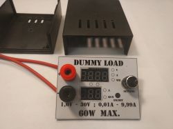
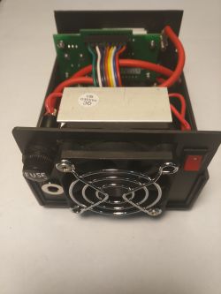
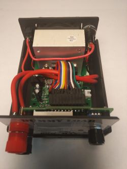
So I decided to make the housing on my own, to match the other components. But more on that later, and briefly, because it's not DIY after all, and you're interested in how it works ...
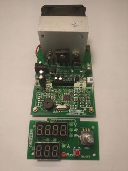
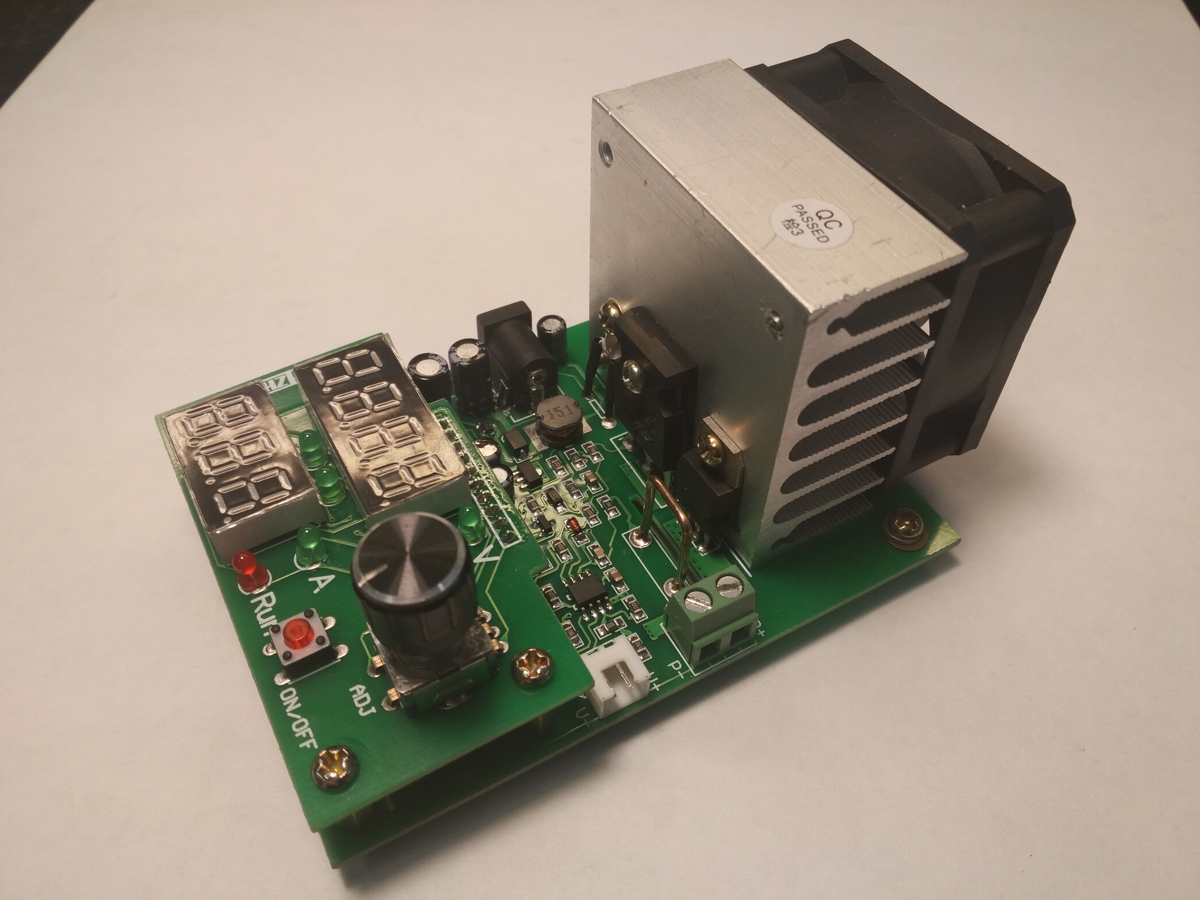
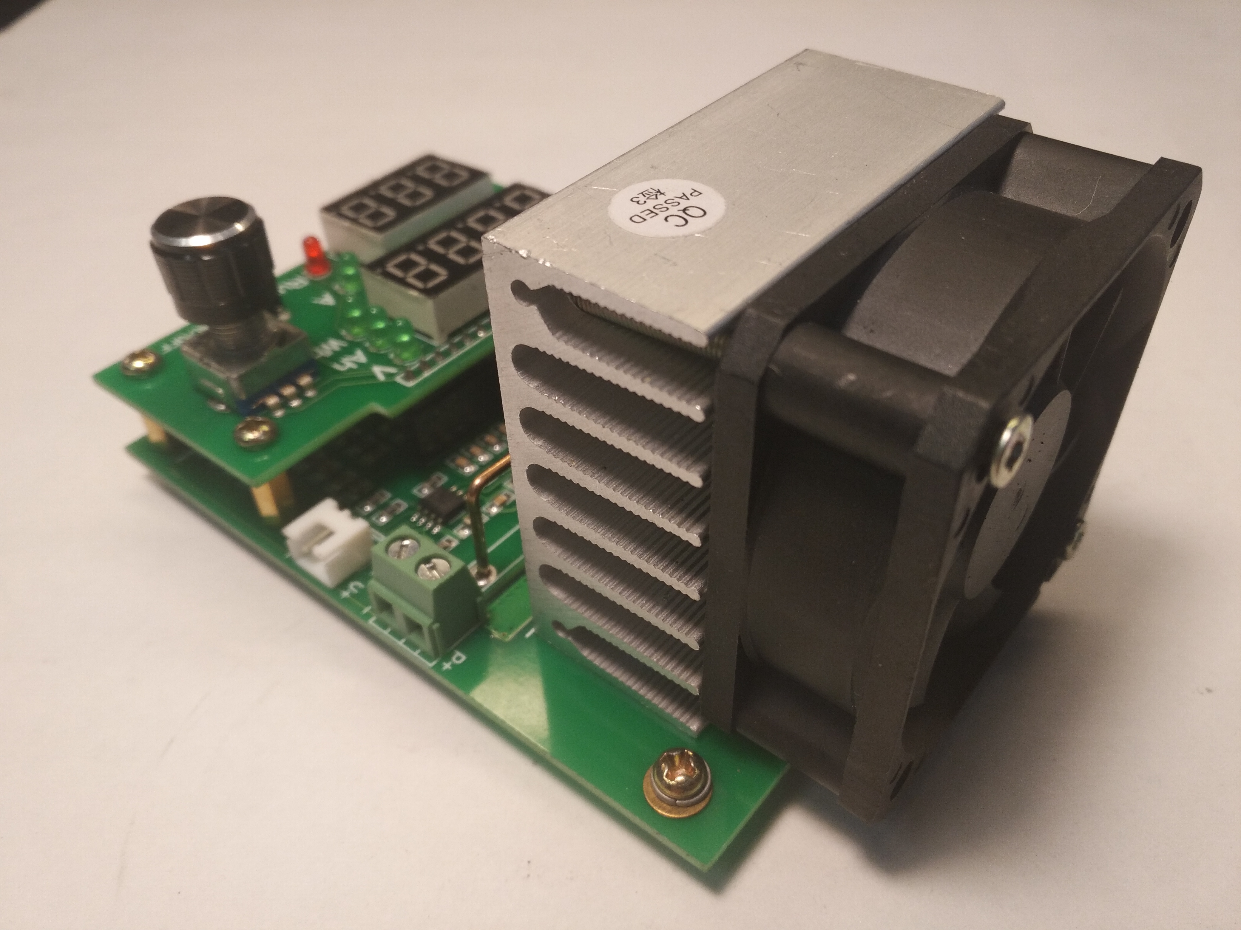
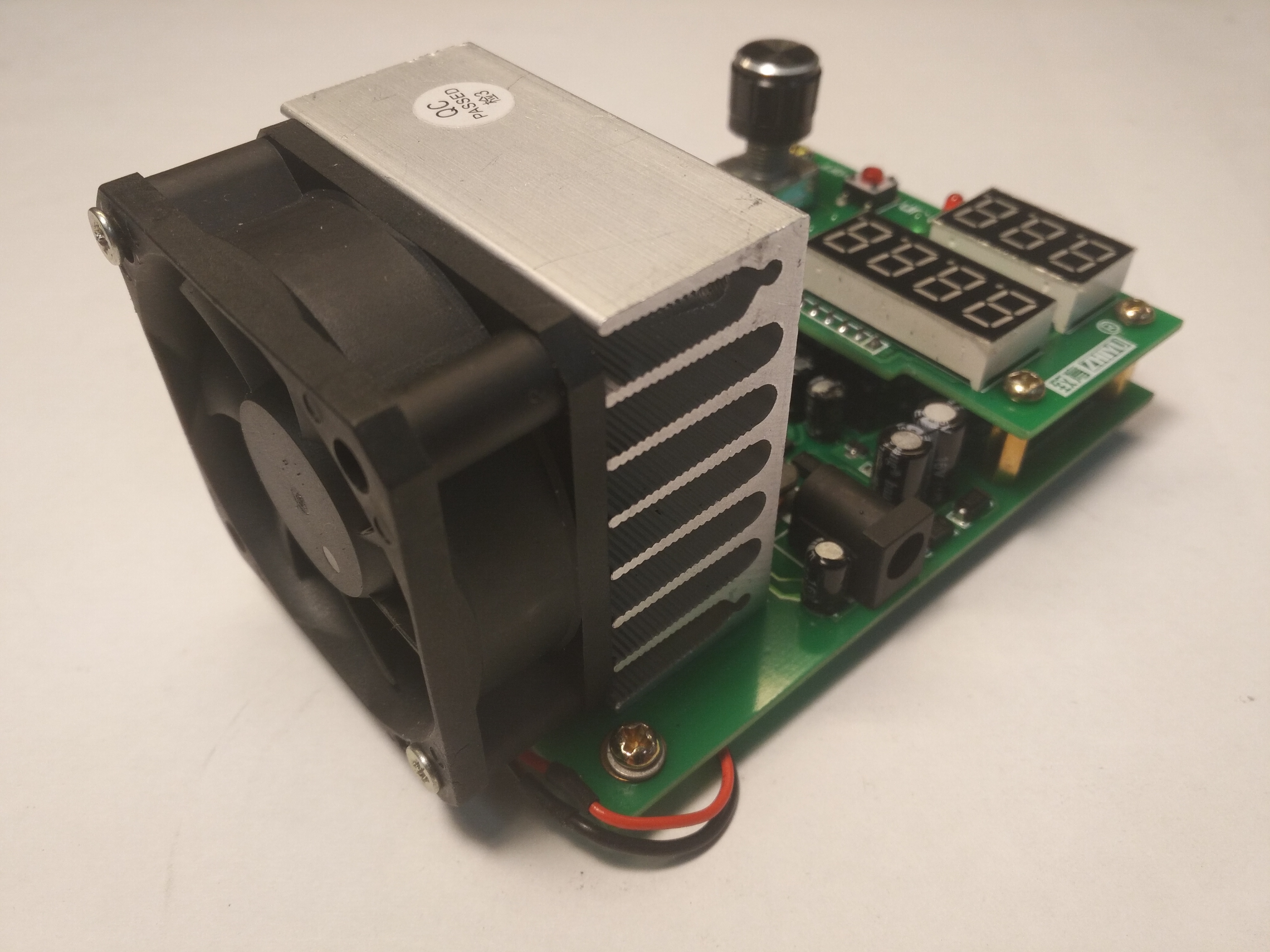
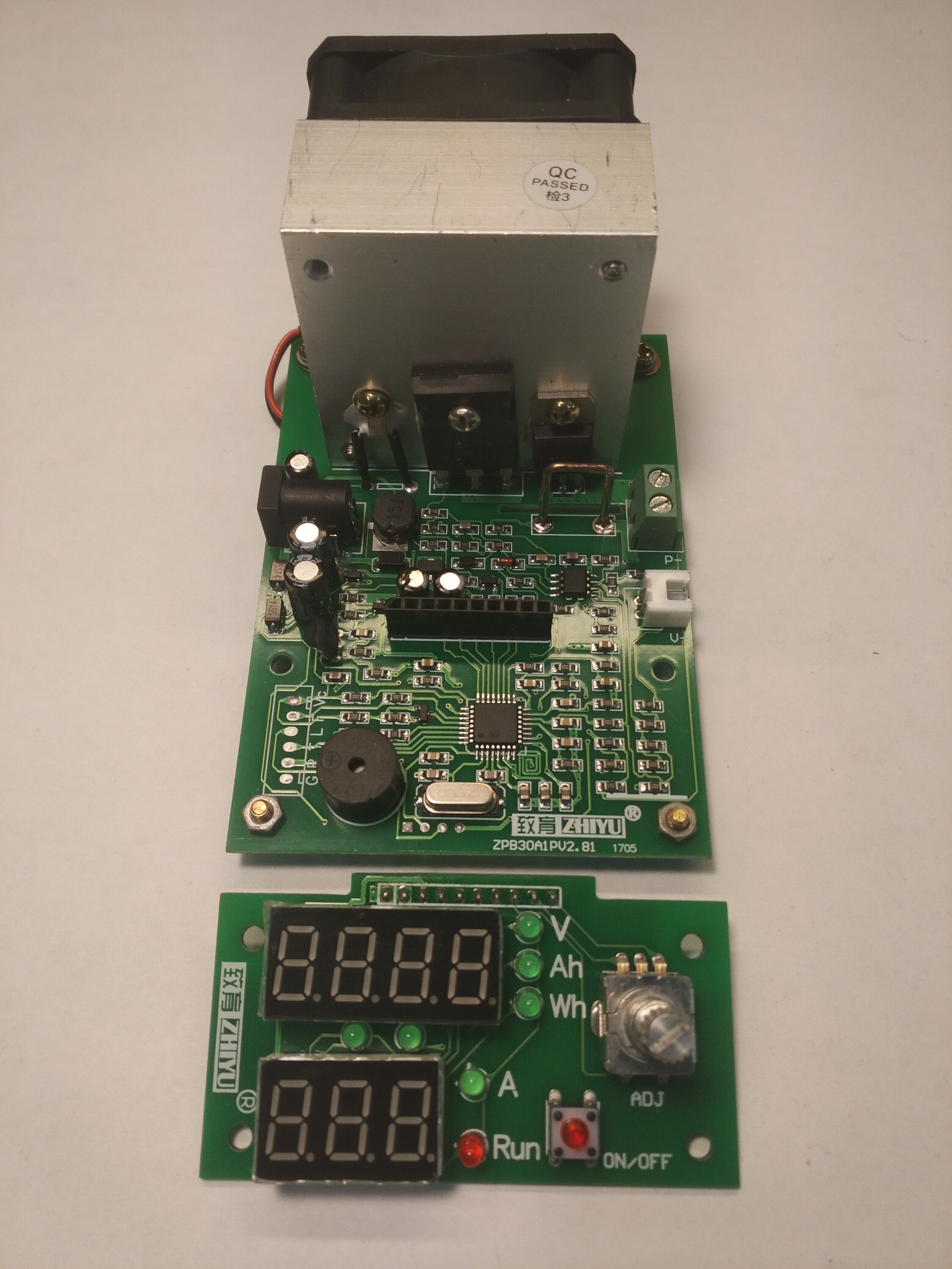
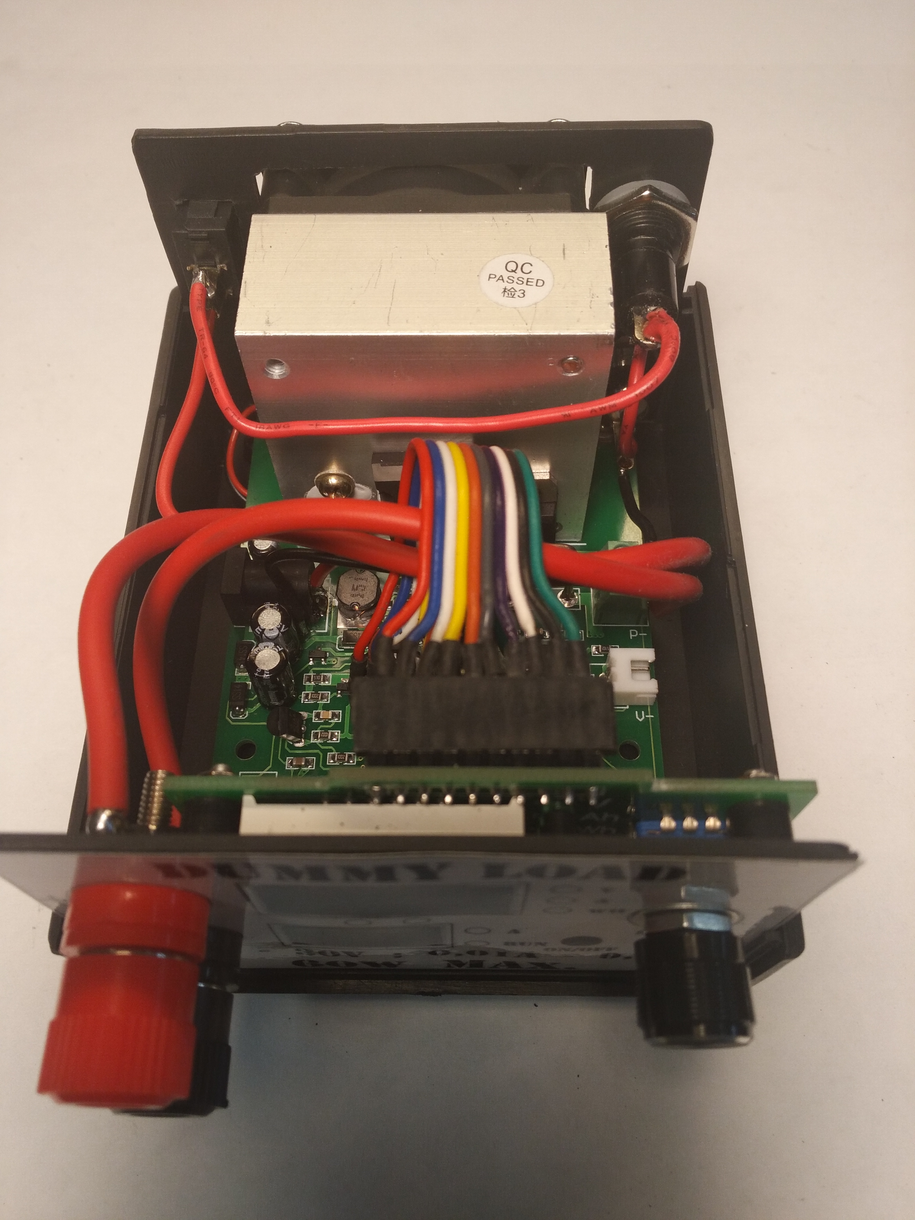
We get something like this from a Chinese:
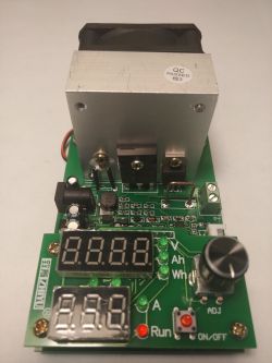

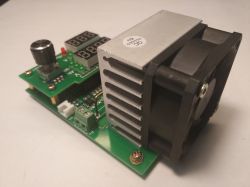

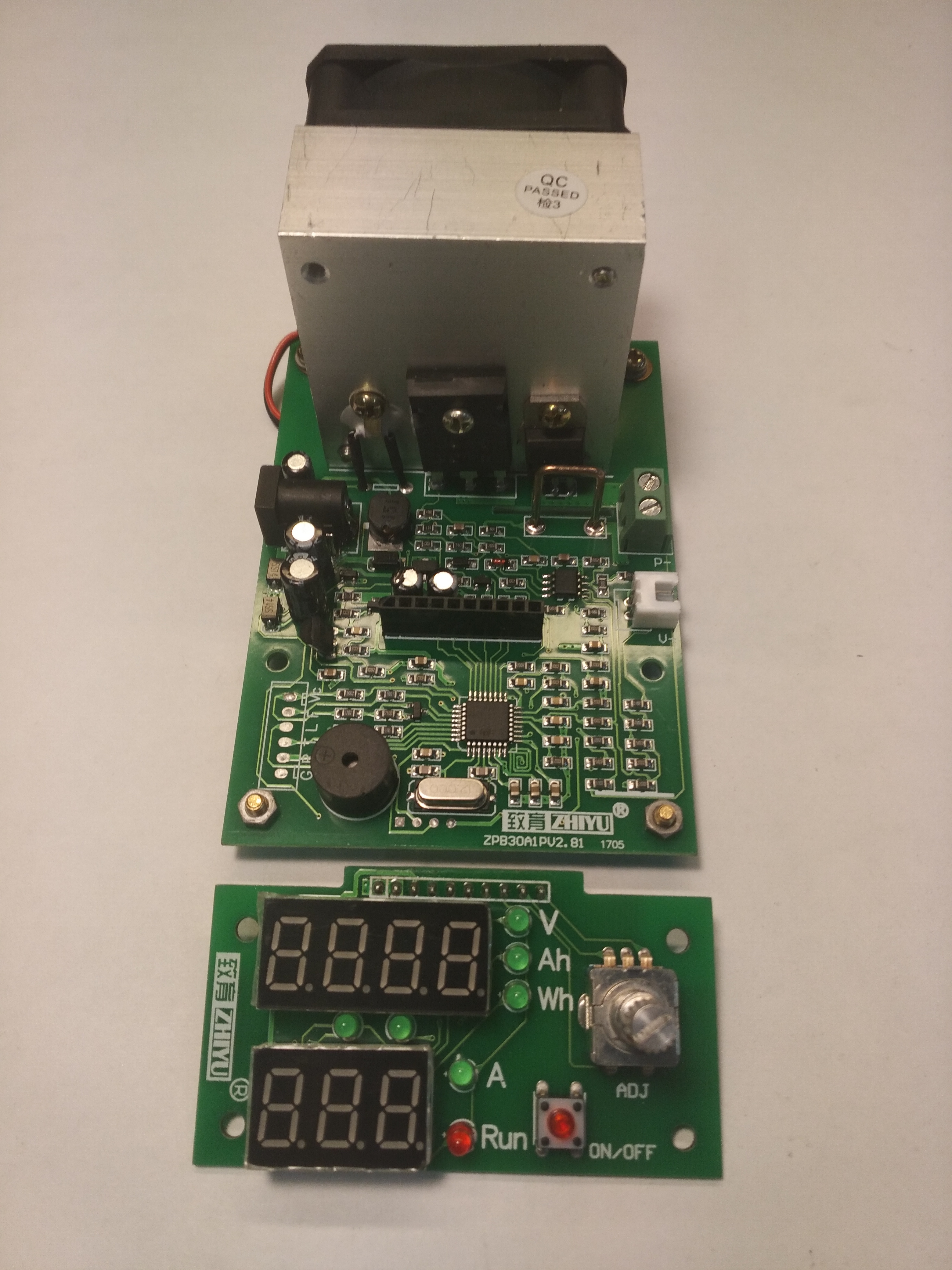
We can break it down into two modules:

At this point, it's time for an anecdote, one time when I tested something, my half asked: "what is this device actually for?" I answered truthfully that the only function of this contraption is to waste electricity. I don't know why, but somehow she didn't understand and still doesn't know what it is for.
In fact, it is a brilliant device, apart from the fact that it "wastes" electricity quite effectively, it can also do several other things.
The load has two operating modes.
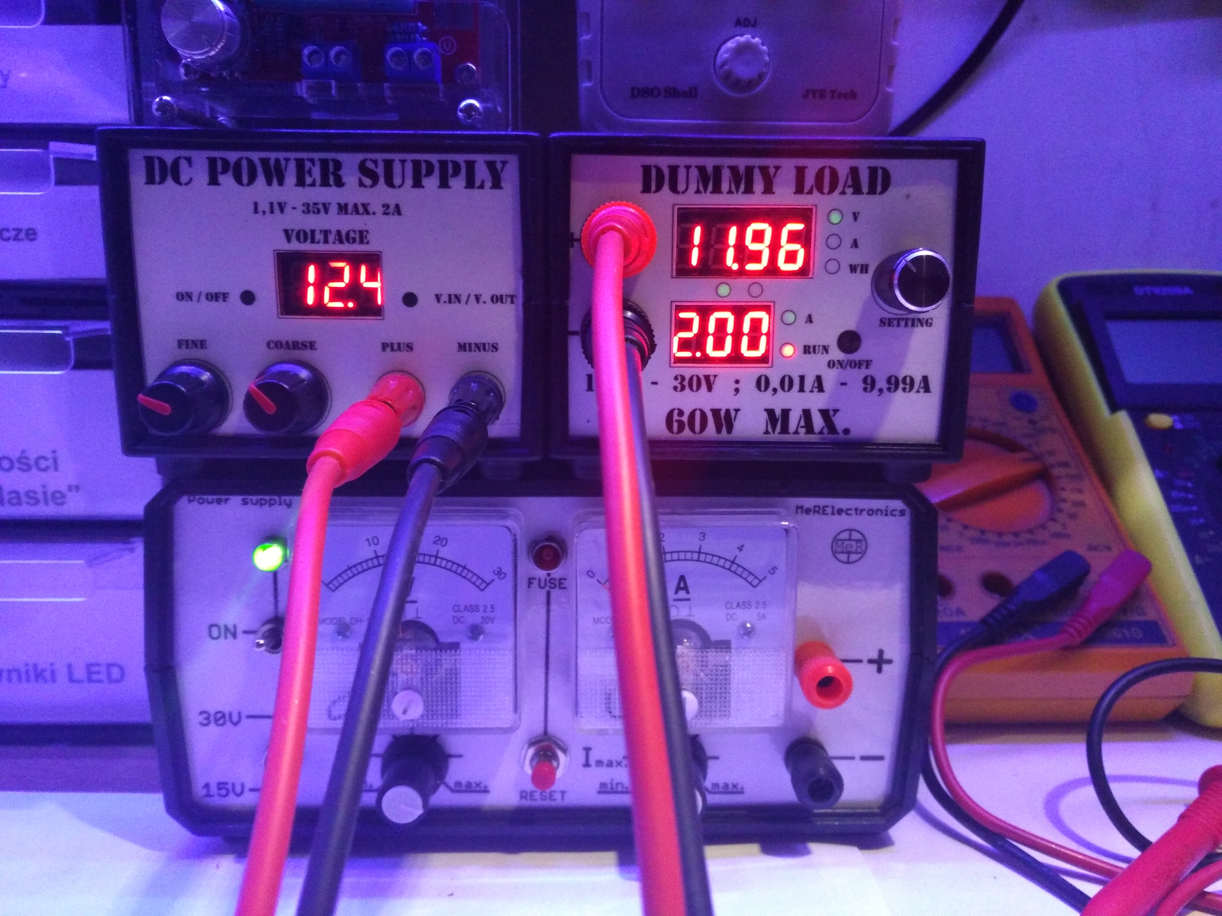
Testing power supplies, where we set the "expected" voltage at the tester's input and the current to be taken from the source. Experience shows that the system works perfectly and that it "bravely" maintains the set current despite voltage changes at the input.
The second mode is used to test all types of batteries. Of course, with common sense, because I remind you that we have a maximum of 60W. Therefore, I do not recommend testing batteries from trucks

because if it is possible, it will take a very long time.
In this mode, we declare the voltage to which we want to discharge the battery, set the current we want to do it and run it in the same way as during the power supply test. Here, however, we can only appreciate this device.
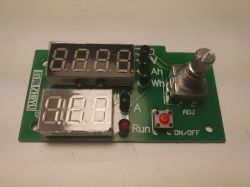
While testing the batteries, the lower display shows the declared current. The upper one displays in turn:
- current source voltage (battery)
- measured Ampere hours
- measured Watt hours
After the measurement is completed (when the battery reaches the voltage value declared at the beginning) the upper display starts flashing, displaying the measured capacity in Ah.

Volta.

Amp-hours (yes I know the letter "h" is missing).
Watt hours (yes, I know "h" should be lowercase, but I really like this font and it only has capital letters).
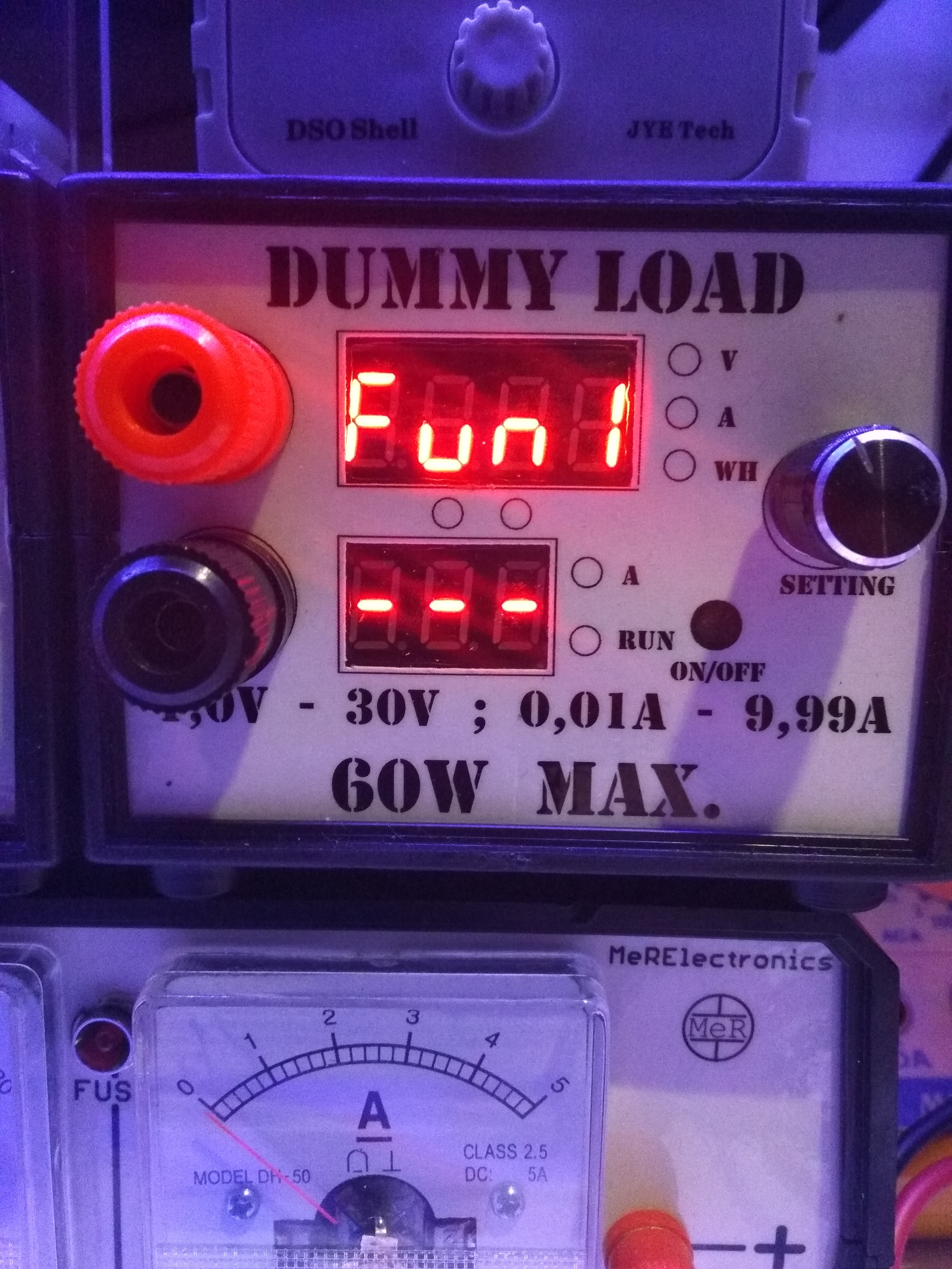
I will say something else about these modes. Well, if we connect the power while holding the On / Off button, something like this will appear on the display:
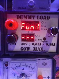
Now we can choose the pulser between 1 and 2.
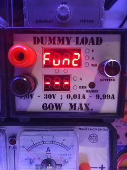
Then confirm with the On / Off button (not by clicking the pulser).
Now an option will appear:
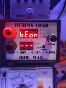
which can be set to
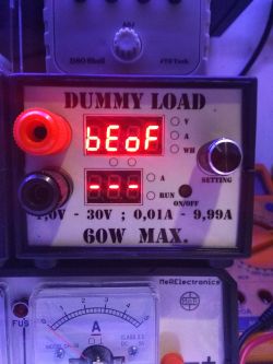
and confirm again with the On / Off button.
The second option is translated into our BeOn / BeOF> Beeper On / Beeper Off, i.e. turning the annoying buzzer / beeper on and off, or whatever you call it. However, in some situations such a beep may be helpful.


In the pictures we can see the power supply as a battery, but I have already tested over 60 pieces of 18650 with this equipment and a dozen or so other batteries and I must honestly say that it is a great device. And everyone should have one in their workshop.
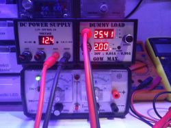
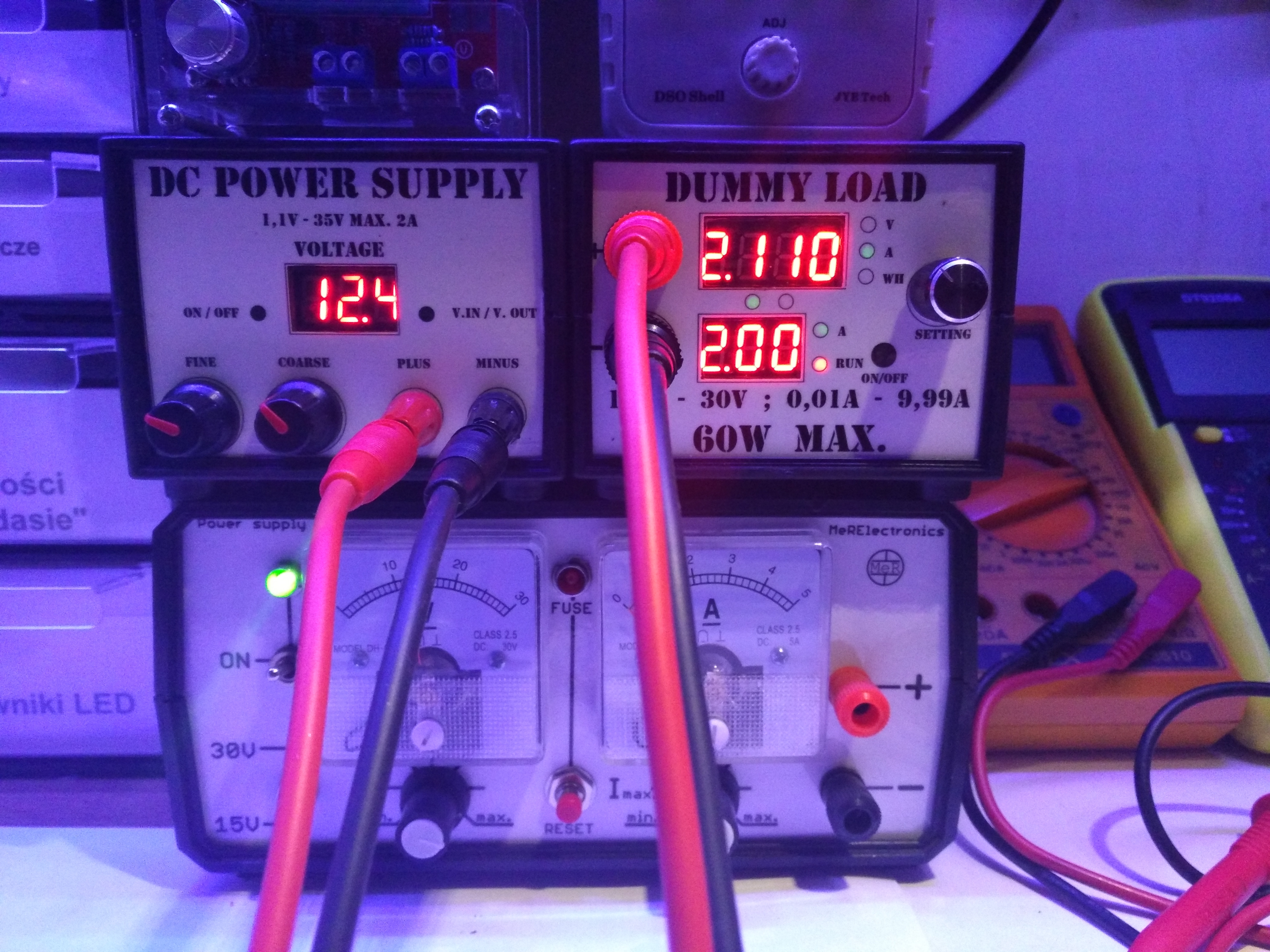
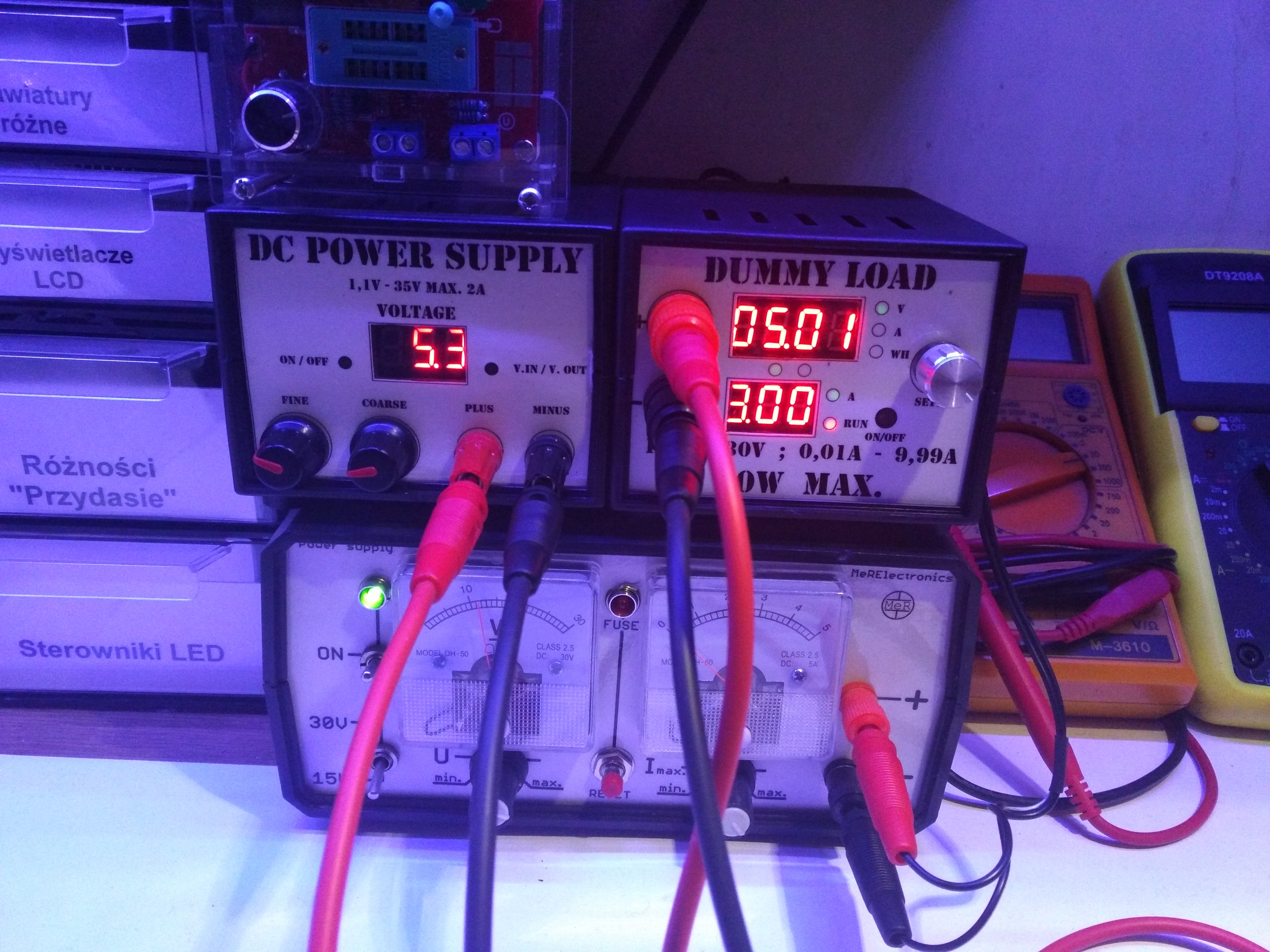
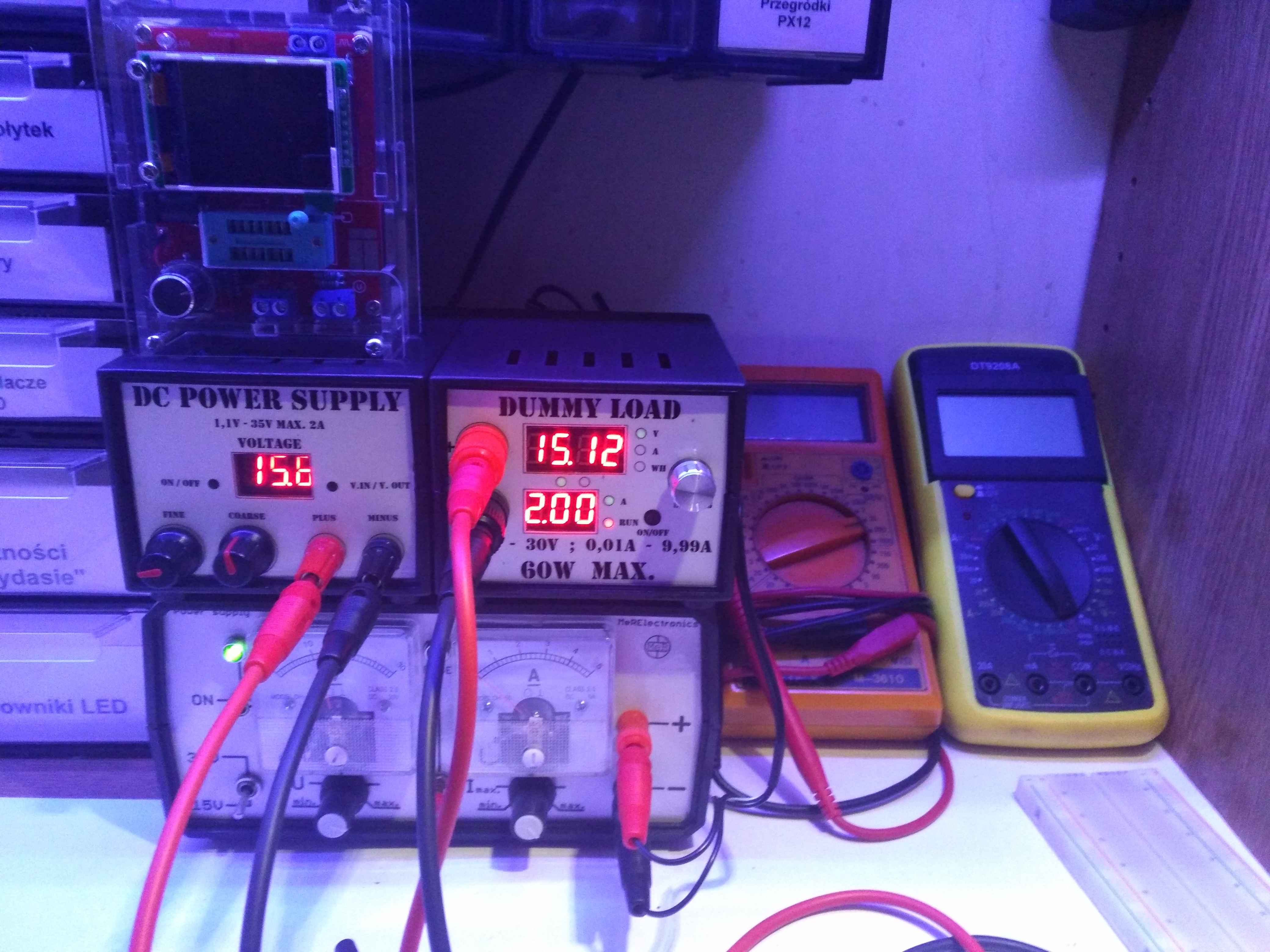
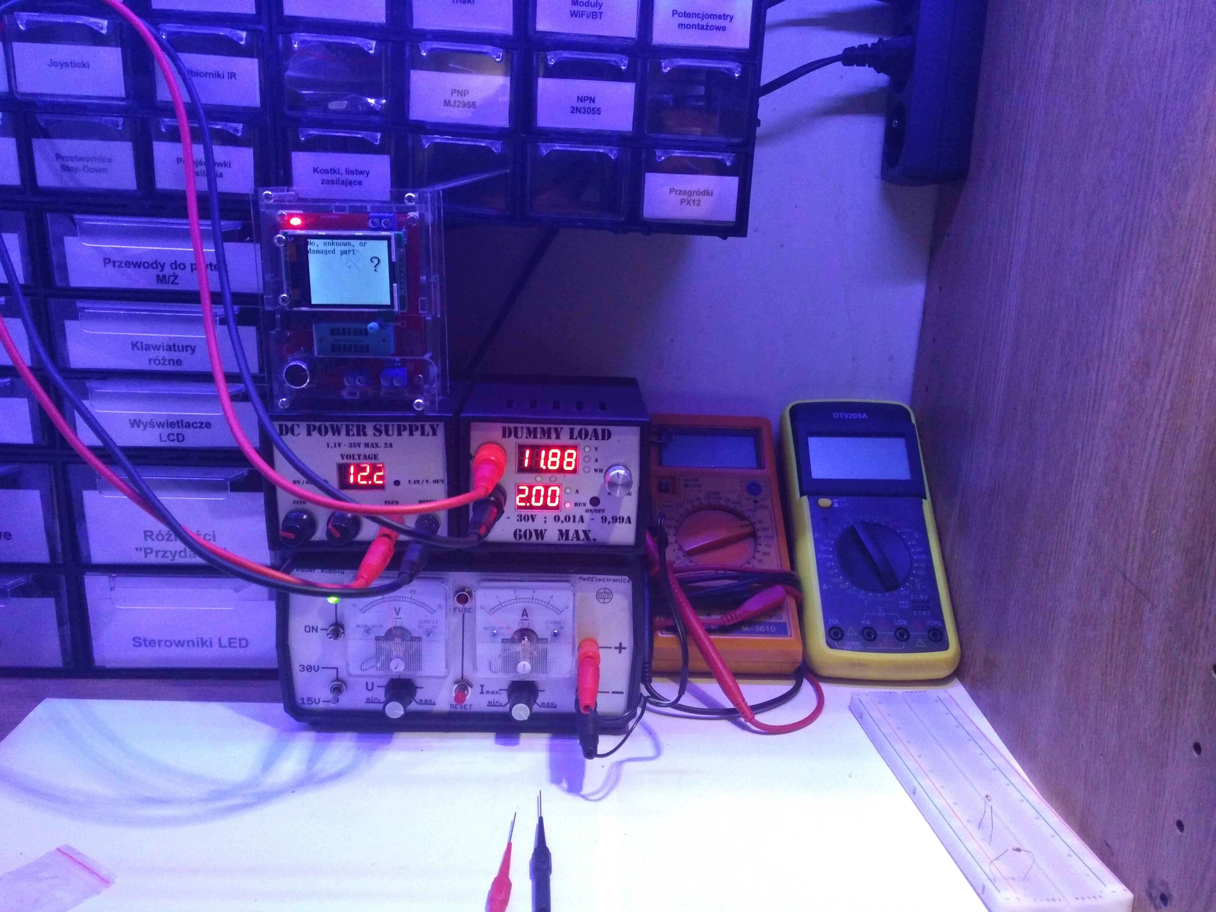
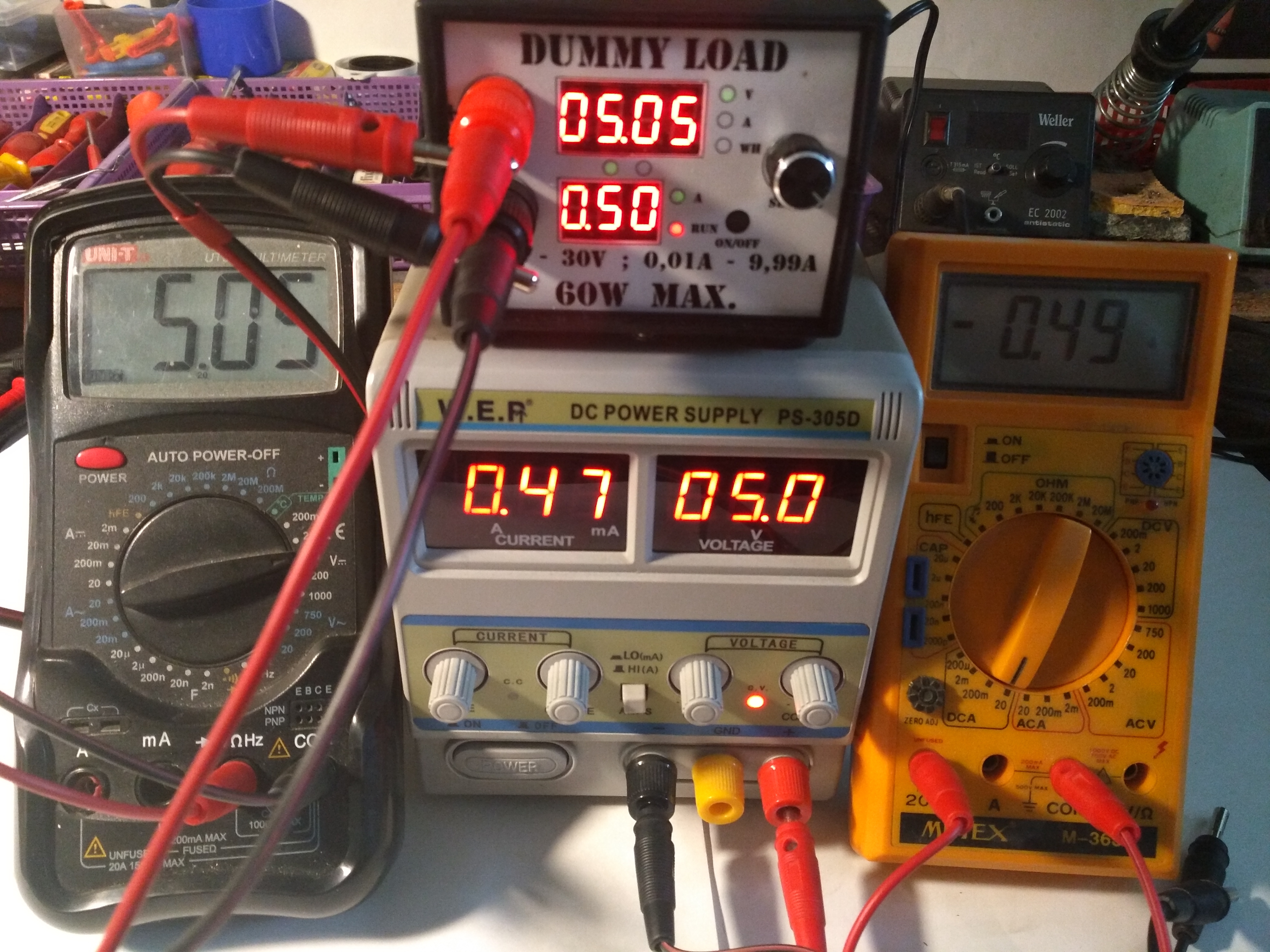
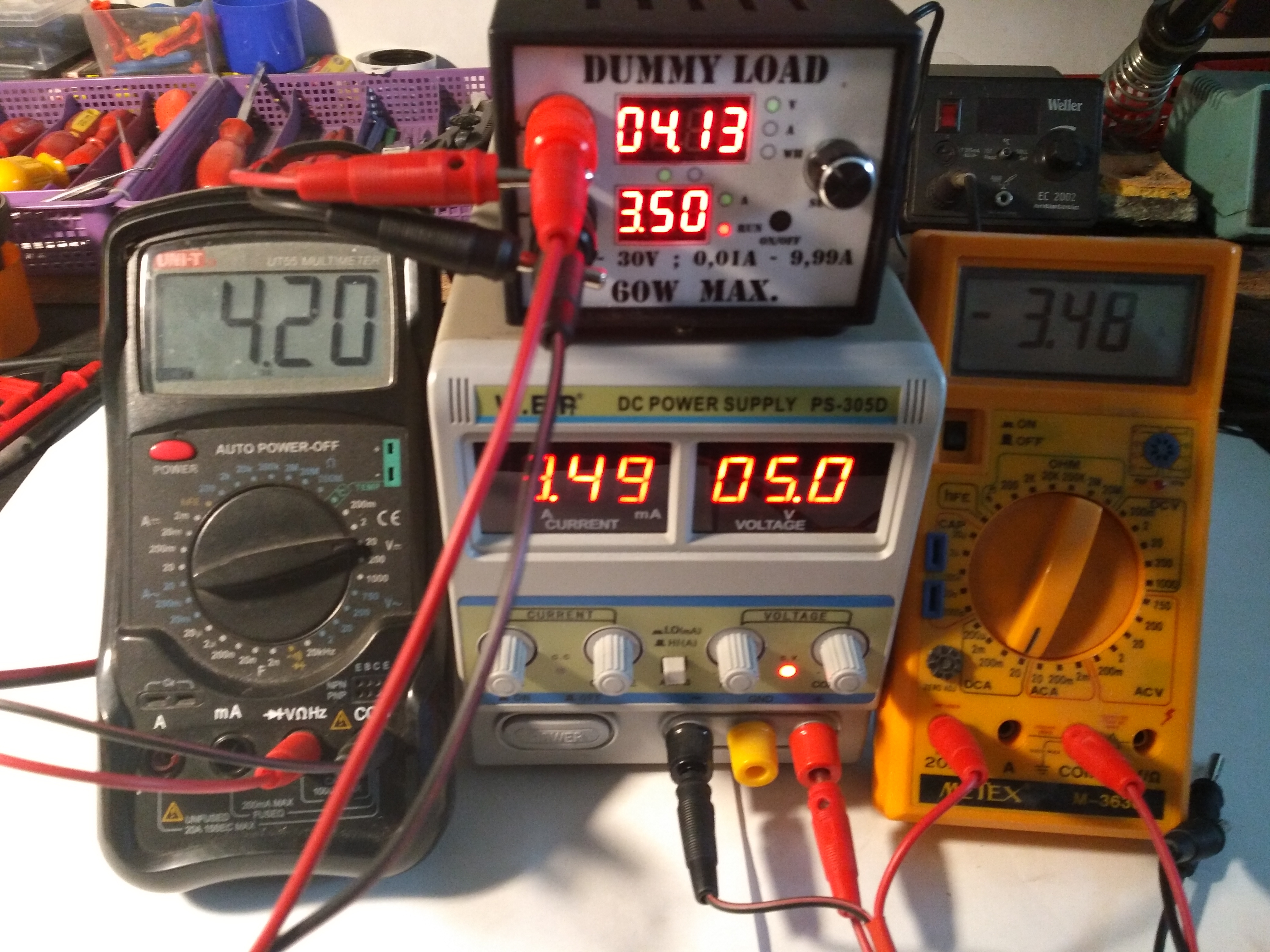
One of the users pointed out to me that some tests would be needed to compare the voltmeter and ammeter readings with external measuring devices. So I took a few more photos.
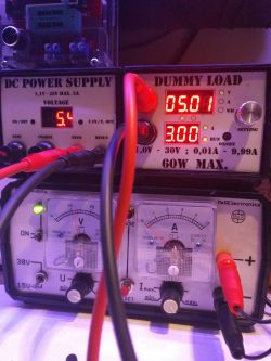
This time, the well-known and popular PS-305D, branded by the WEP company, played the role of the power supply.

5V 0.5A
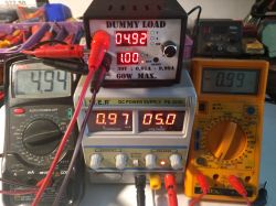
5V 1A
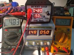
5V 1.5A

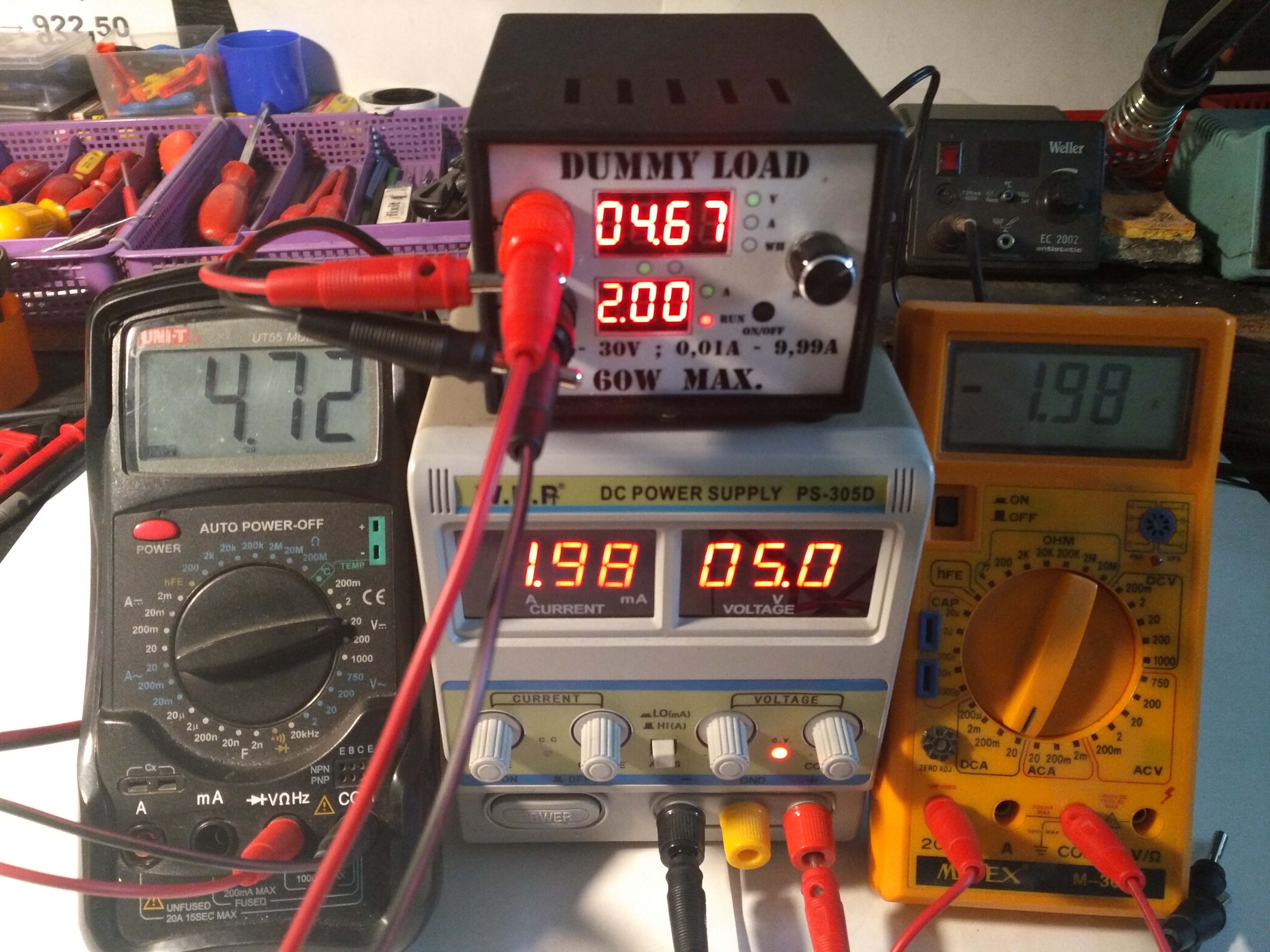
5V 2A

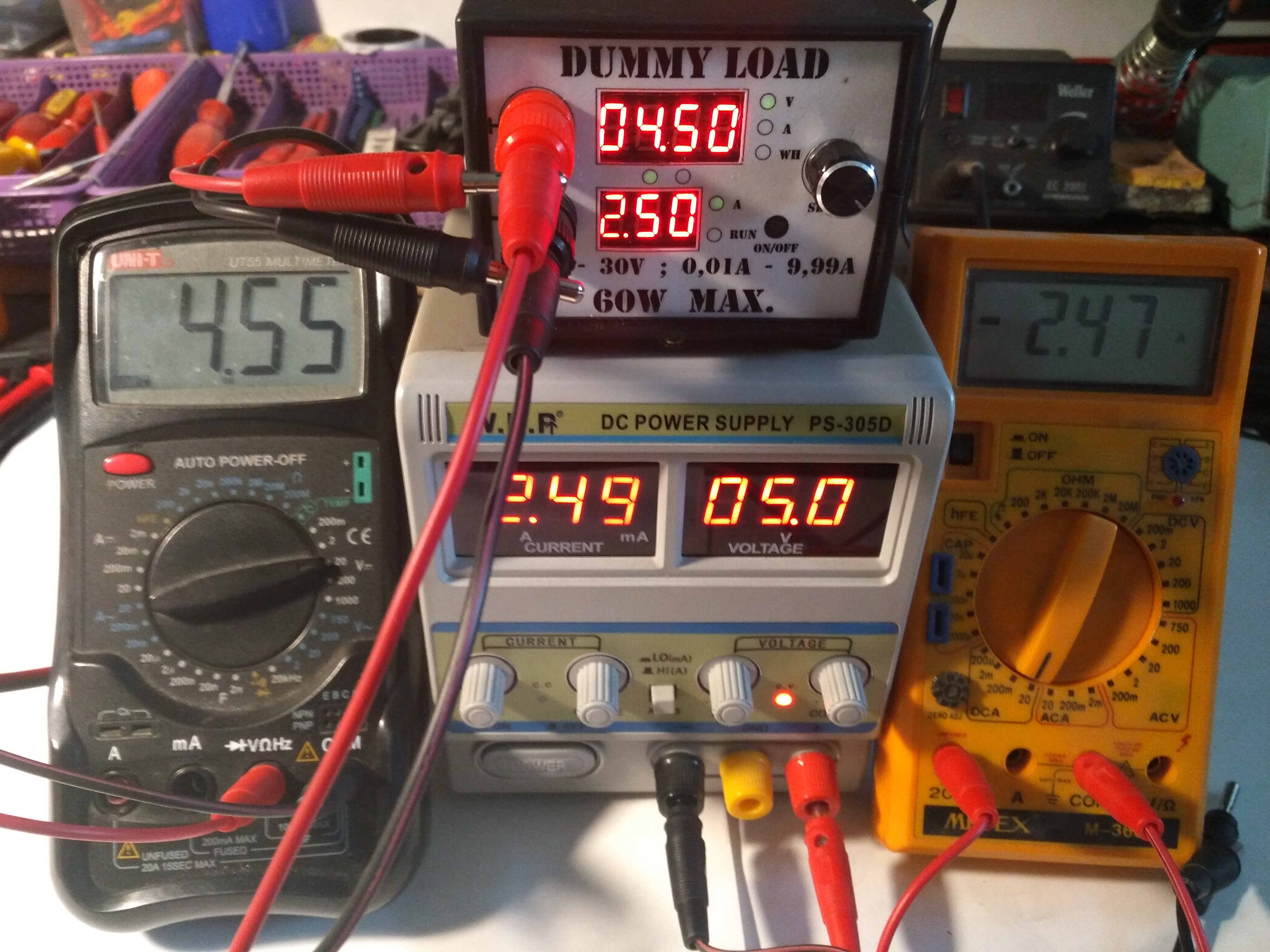
5V 2.5A
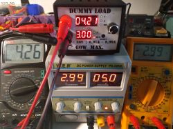
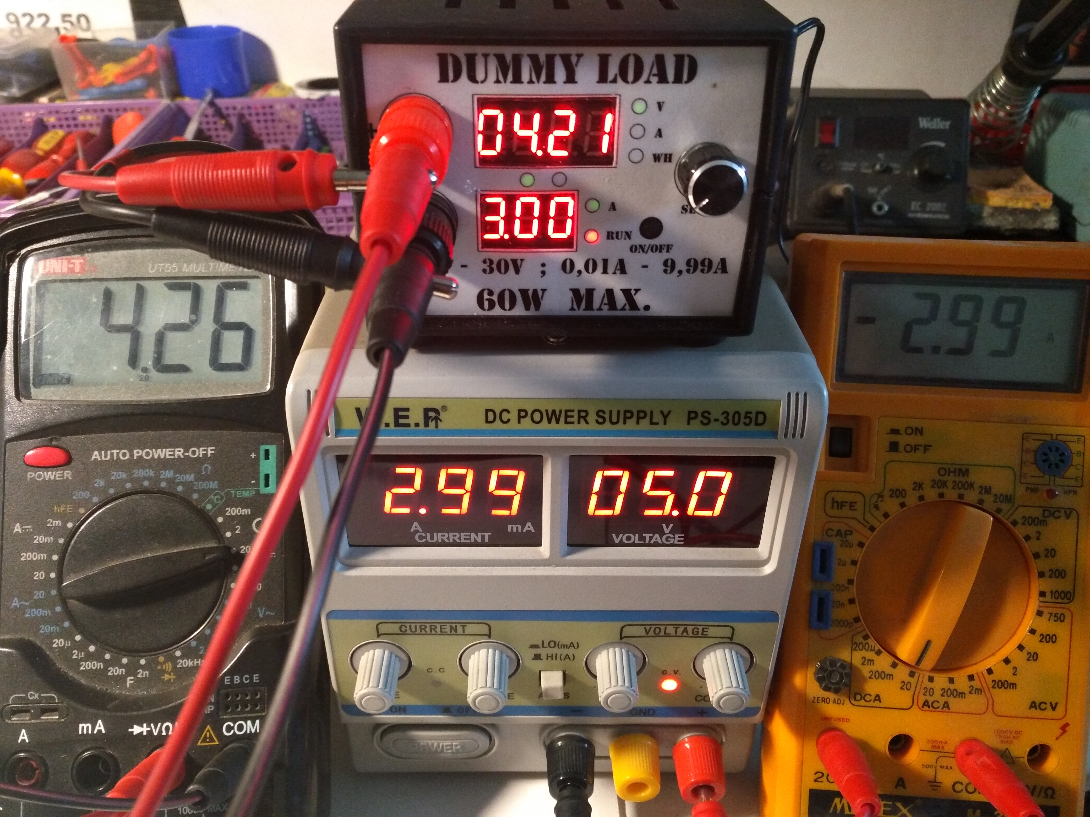
5V 3A

5V 3.5A

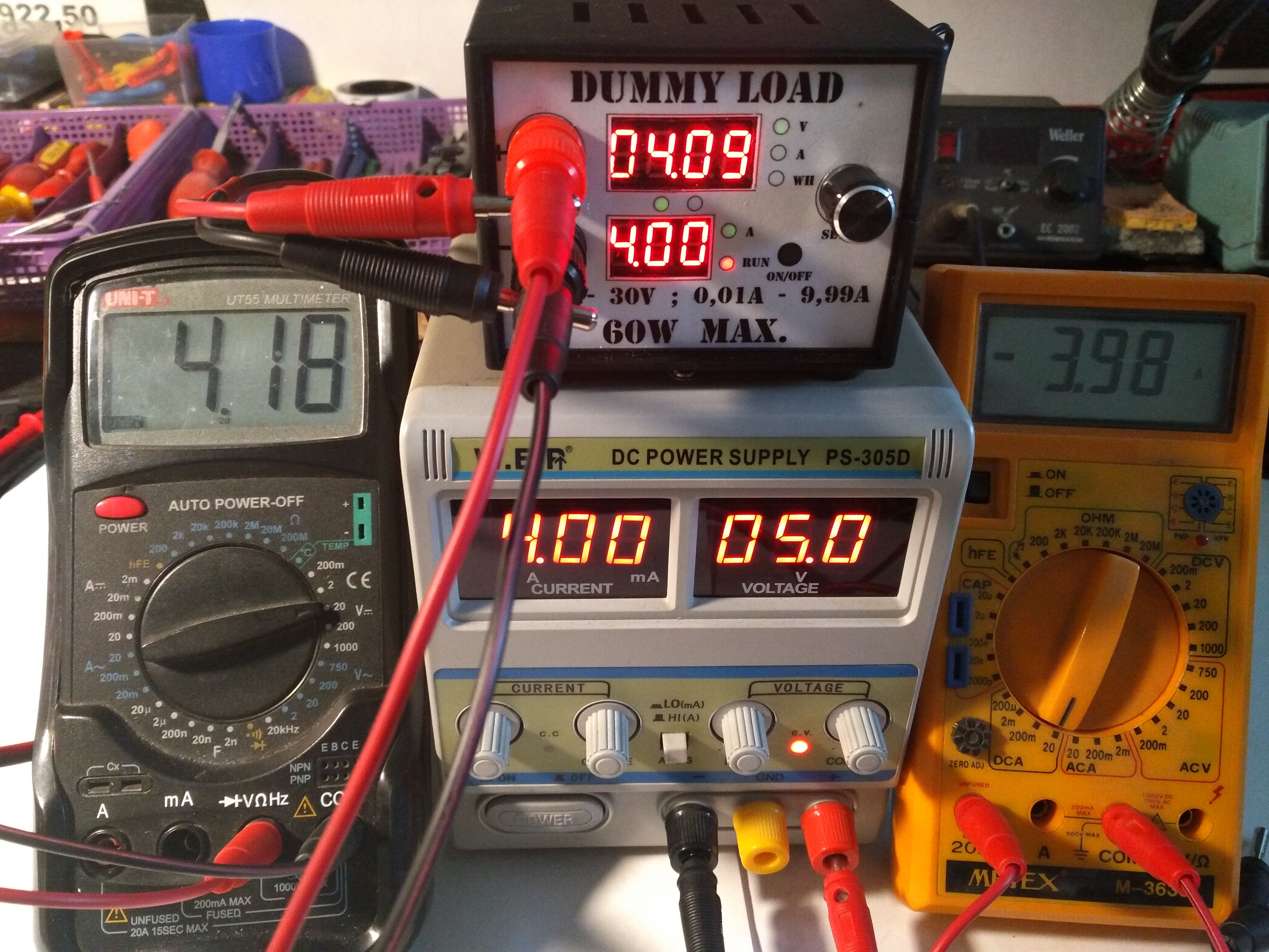
5V 4A

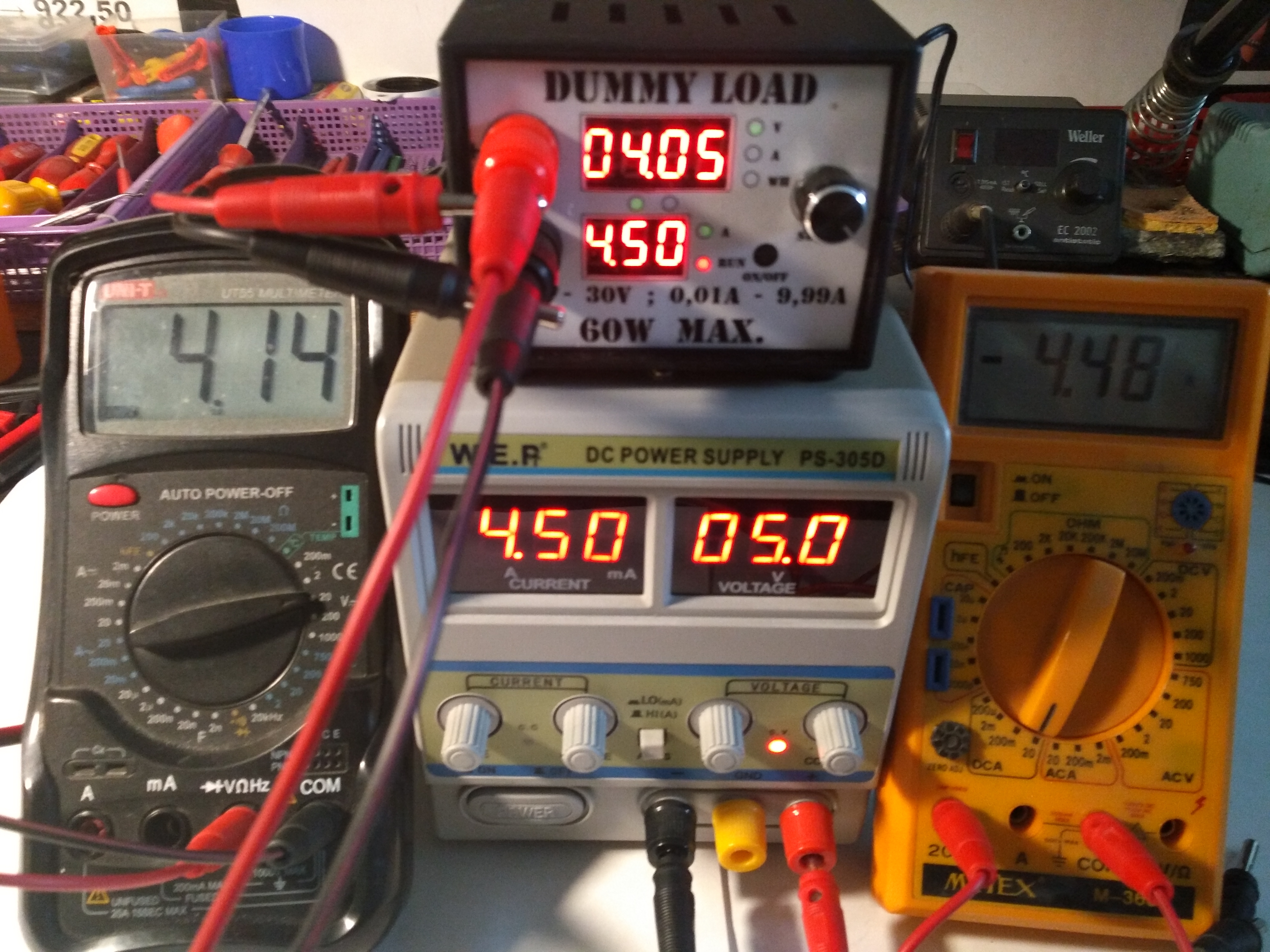
5V 4.5A
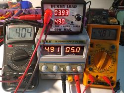
5V 4.9A
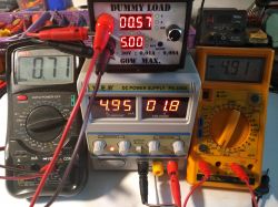
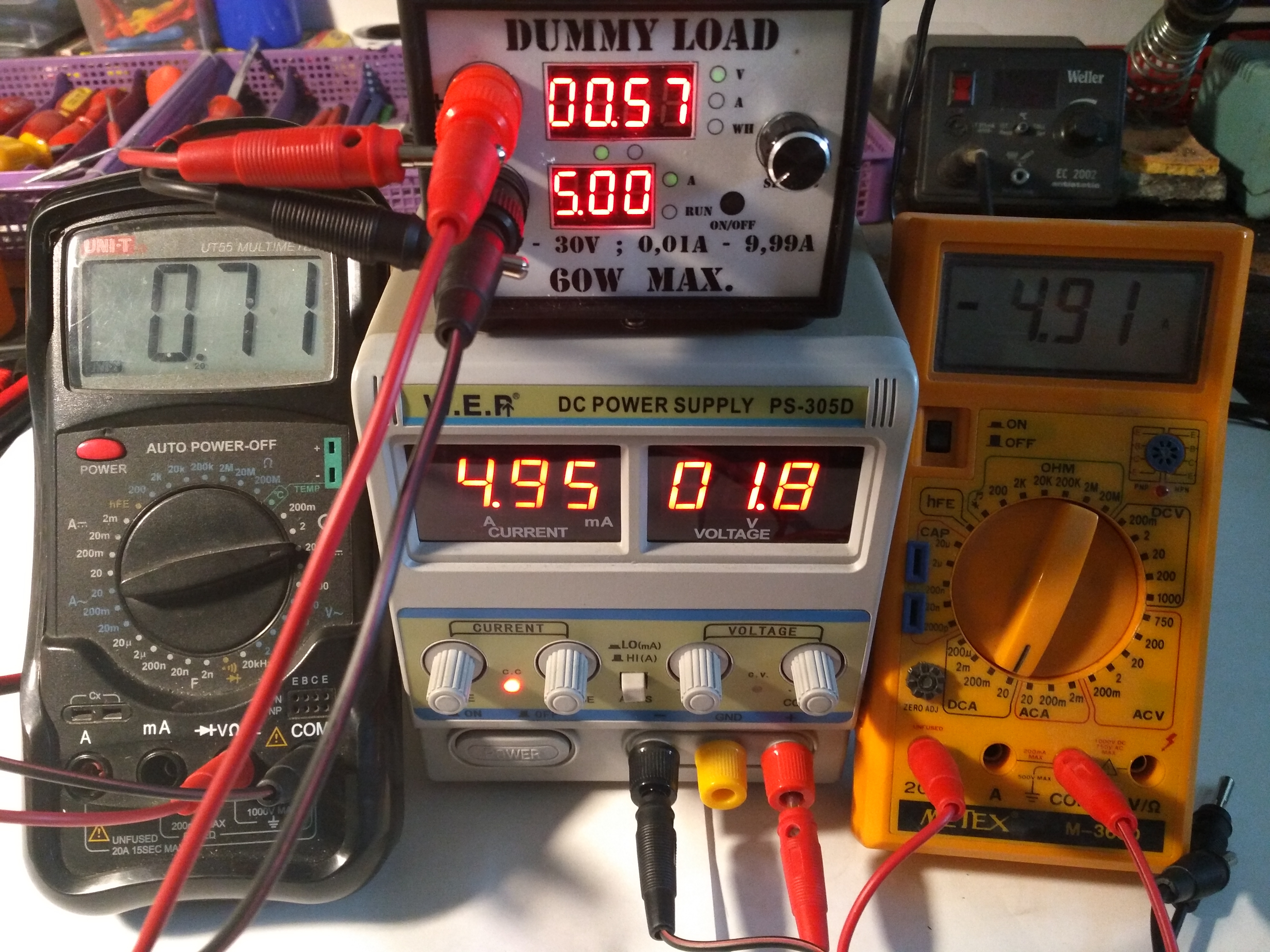
5V 5A, at this point the power supply has run out and the protection has worked and the power supply has switched to Constant Current mode.
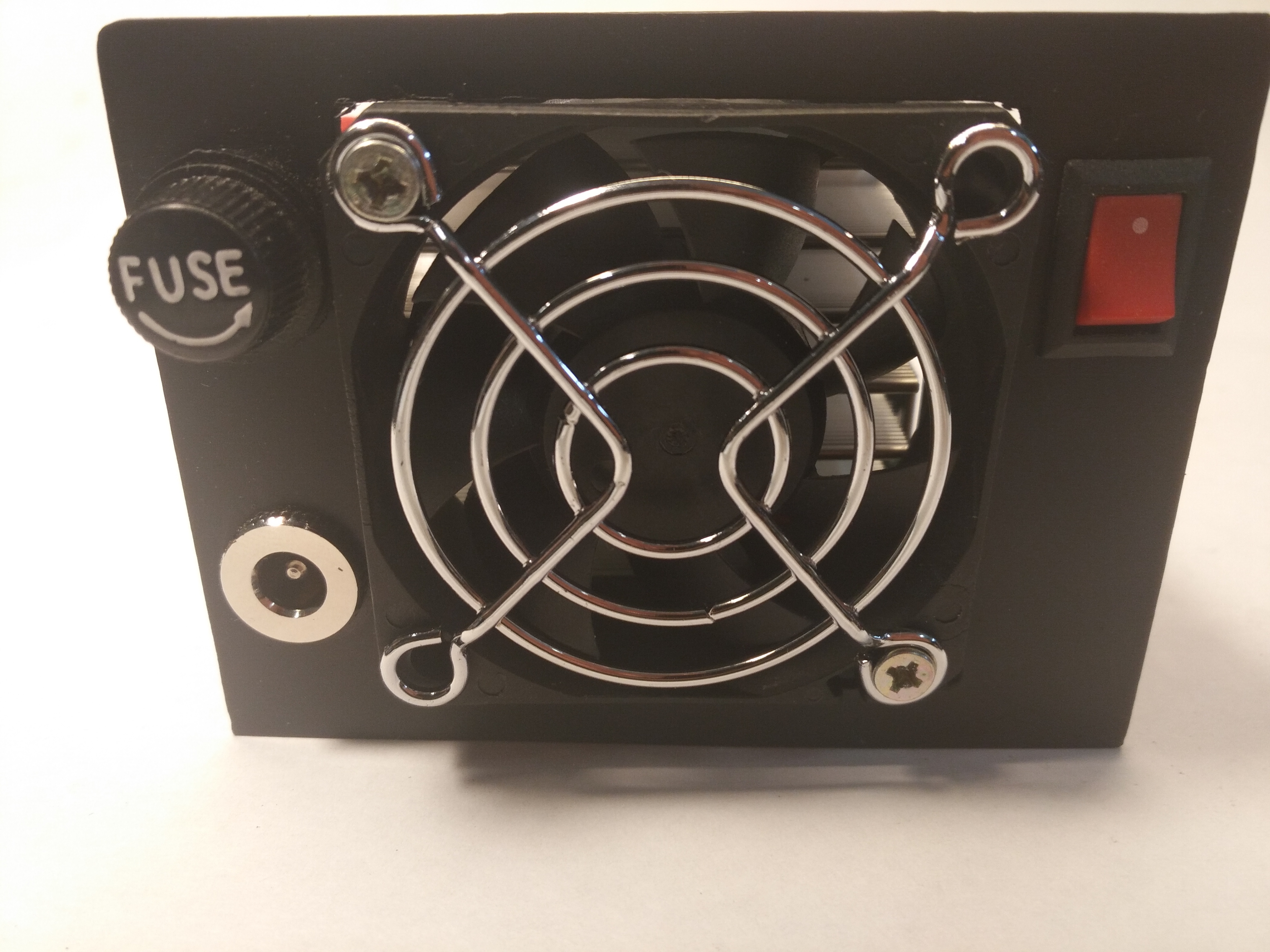
Finally, a few more words about a cheaper and much more functional housing.
I do not know why the manufacturers of enclosures give external dimensions instead of internal ones, which makes it difficultis to buy the housing remotely (online) when it is not possible to try on whether the system will fit). For this I am posting some photos of my solution.
The housing is Z3A.
Panel made in Corel X6 or X7, I don't remember.
A few photos.
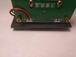
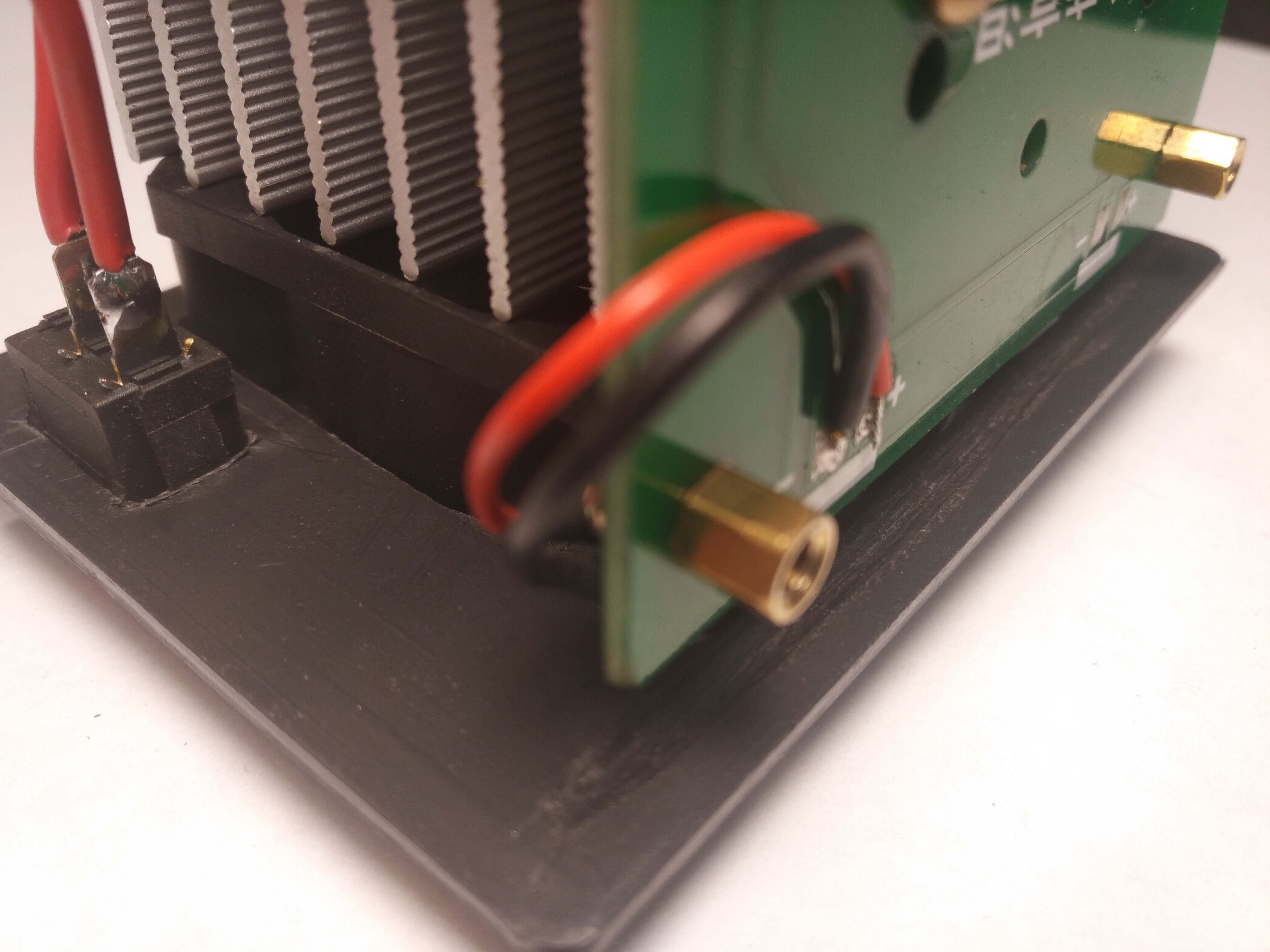
We separate the whole to mount the part with displays on the front panel. We have to make some extra tape, flexible enough to move the panel about a centimeter to the right. Otherwise, it will be difficult to stuff the test sockets later.
We put on properly cut "thermowells" for LEDs:
and screw the whole thing to the previously made panel.
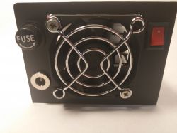
We make appropriate holes in the rear panel:

And also milling for the plate, because the housing is about 1mm too short.
The whole thing looks like this:


Comments
The (other) housing is sold by a company from Wrocław - catalog number BTE-433. [Read more]
I also bought such a load once. In my case, the Chinese installed a bad thermistor on the heat sink (10k instead of 50k) and the fan control did not work as it should. I replaced the thermistor with... [Read more]
This is a way out, but I completely don't like it. Besides, there are no descriptions and it is not known what which LED means. [Read more]
It's time to ask a slightly off topic - what silicones do you use? The cross-section looks quite correct. Are they relatively flexible? I wonder if someone bit the soft for this. Until it asks for... [Read more]
Wire thickness 4mm, wire cross-section 1.3mm2. Maximum current 42A. When it comes to flexibility, they're Mega Flexible. [Read more]
Hello, I would like to draw your attention to the fact that when testing power supplies, the impulse response is also important (over-regulation and delays in determining the voltage), hence when testing... [Read more]
I've had this artificial load for a long time. In my version there is such a slight drawback that the very beginning of the current setting range - somewhere down to 0.15A - is quite difficult to set... [Read more]
I saw even the 300W version, but the price put me off. However, I will buy some one day. [Read more]
Have you tested any converters already? I used to have such an artificial load a self-made, which was faithfully used for batteries, until suddenly on the PC power supply it started to excite, it's... [Read more]
Yes. You can torture Chinese "drivers" quite well, sometimes they literally squeak and sizzle. Several articles about testing inverters will be available soon. If a colleague read the topic carefully,... [Read more]
But he read and ... There's no way you've done this before ;) As for I think I have similar, or the same, only the original ones that I got with the meter. Amazing, flexible as a string,... [Read more]
Could it be a diagram from mdiy.pl? [Read more]
How about the accuracy of the current and voltage measurement? [Read more]
I added some photos to the first post. You can see how the current and voltage measurements behave. [Read more]
No. Generally an executive transistor and two WO, one error and one measurement. Nothing special. A piece of universal tile. [Read more]
Measurements look ok, one could work on eliminating the voltage drop on the connections but generally acceptable. Thanks for the measurements. [Read more]
The operational amplifier in this load is particularly fast, and it does not have low current efficiency, so in combination with the MOS and the gate capacity, it should not be excited. Unfortunately,... [Read more]
Do you know what the small, white connector on the board is for? [Read more]
I have no idea. I was wondering about that too, but I don't care so much about this information as to pursue the topic. [Read more]