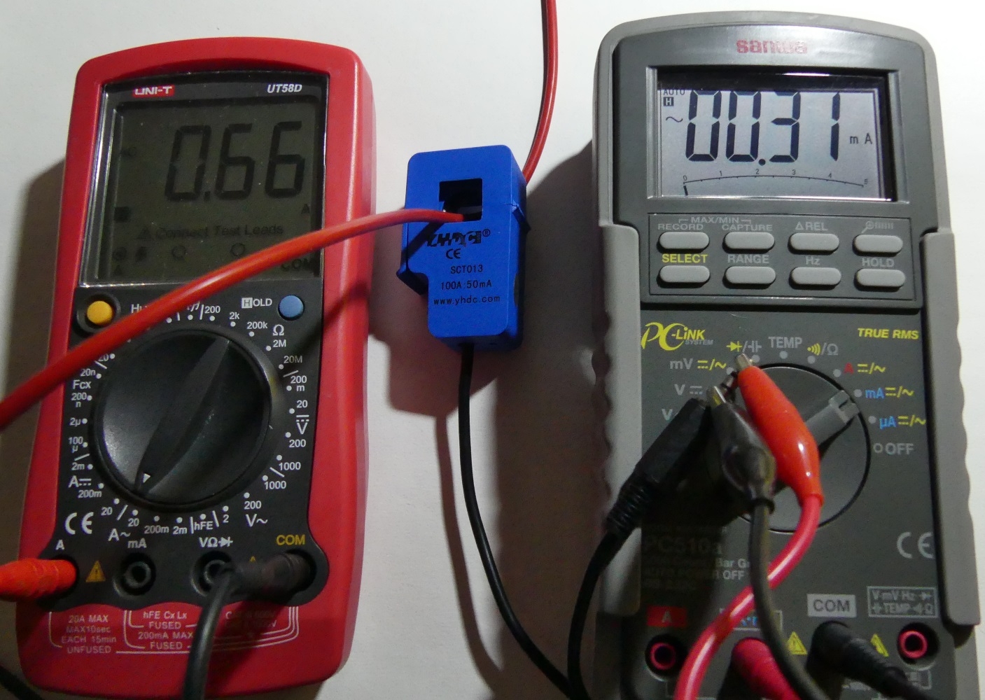
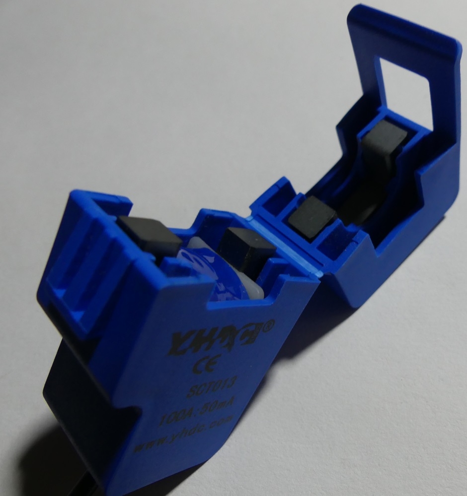
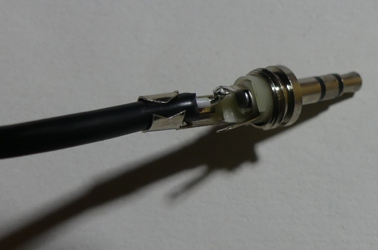
The split-core current transformer shown in the photo is available at a low price on many auction portals and online stores. The transformer has the parameters of 100A / 50mA. So when 100A alternating current flows through the cable through the transformer, the AC milliammeter at the transformer output will show 50mA. The current ratio of the transformer is 2000. The output signal is led out on a mini jack connector. The transformer casing enables the core to be opened and the conductor to be measured is enclosed.
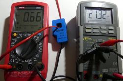
To begin with, we connect a 140W 230V bulb, a current of 0.66A flows in the circuit, the milliammeter shows 0.31mA.
According to the transmission 2000, a current of 0.62A should flow in the tested circuit. The multimeter shows 0.66A, however the measuring range is very large (100A) and measurement errors will always occur. Here more about the transformers and available models:
https://www.poweruc.pl/collections/split-core...urrent-transformer-sct013-rated-input-5a-100a http://en.yhdc.com/product1311.html?productId=401 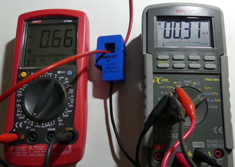
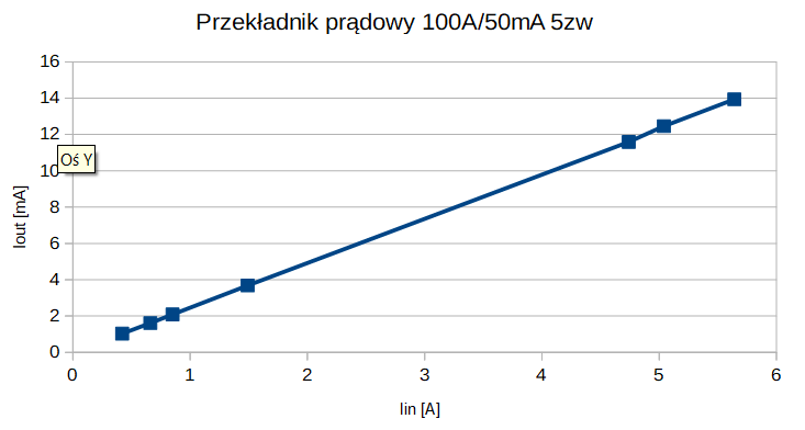
By checking the measurement results at several points, you can see the linear characteristics of the transformer:
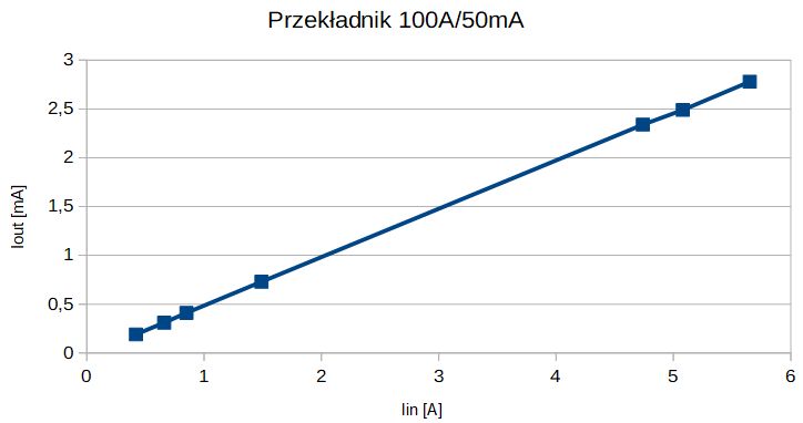
| Iin [A] | Iout [mA] | x2000 |
| 0.42 | 0.19 | 0.38 |
| 0.66 | 0.31 | 0.62 |
| 0.85 | 0.41 | 0.82 |
| 1.49 | 0.73 | 1.46 |
| 4.74 | 2.34 | 4.68 |
| 5.08 | 2.49 | 4.98 |
| 5.65 | 2.78 | 5.56 |
For the measurement of smaller currents, it is worth using a transformer with a smaller measuring range. For the test, we put 5 turns on the transformer core, which changes the ratio and output currents,
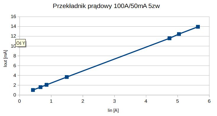
| Iin [A] | Iout [mA] | x400 |
| 0.42 | 1.03 | 0.41 |
| 0.66 | 1.61 | 0.64 |
| 0.85 | 2.09 | 0.84 |
| 1.49 | 3.68 | 1.47 |
| 4.74 | 11.59 | 4.64 |
| 5.04 | 12.46 | 4.98 |
| 5.64 | 13.94 | 5.58 |
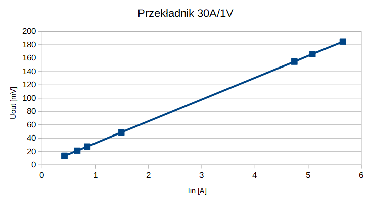
Another type of transformers are those with the output voltage depending on the current flowing in the tested line.
An example of a 30A / 1V transformer. A separate description of the transformer here
SCT013 30A / 1V . The input current in A divided by 30 should produce the corresponding output voltage in V.
Alternating current of 0.66A causes the appearance of a voltage of 21.32mV at the output.
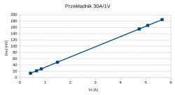
| Iin [A] | Uout [mV] | x30 |
| 0.42 | 13.64 | 0.41 |
| 0.66 | 21.32 | 0.64 |
| 0.85 | 27.52 | 0.83 |
| 1.49 | 48.8 | 1.46 |
| 4.74 | 154.7 | 4.64 |
| 5.08 | 166.1 | 4.98 |
| 5.65 | 184.5 | 5.54 |
By recording the output voltage of the transformer, we can, for example, examine the current consumption in the home electrical installation.
What applications do you see for cheap transformers with limited measuring accuracy? 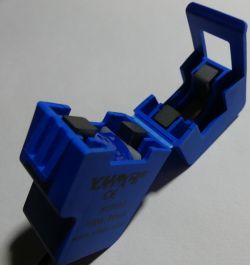

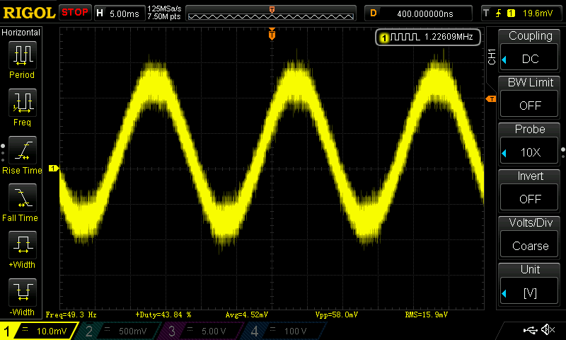
The transformer can be transformed into a primitive oscilloscope probe for observing the waveform of current changes.
Below is the shape of the current consumed from the network by a 100W bulb and a 13W LED:

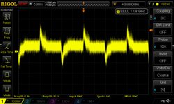
Inrush currents of, for example, different types of light sources can be observed:
The simultaneous recording of the voltage and current waveform allows to determine the received active and reactive power,
examples of differences between power supplies with and without APFC:


Comments
The cheapest transformer is a ferrite core with a wound winding and terminated with an appropriate resistor value. The fact that the disadvantage of such a solution is the lack of a constant component,... [Read more]
@_lazor_ necessarily, such materials are lacking in articles, most things can now be obtained as modules, but such low-level DIY can come in handy in many cases. [Read more]
I am thinking about the construction of a measuring device which could measure the current consumed by a typical electric motor simultaneously on all phases, e.g. in order to detect e.g. a weaker current... [Read more]
I did some transformer measurements comparing to the waveform from the I-prober 520 probe. In a word of introduction, the measurements are illustrative and it seems to me that I plugged in with the probe... [Read more]
I have been working on the construction of an electricity meter (3 phases) for a long time. I have already purchased most of the elements on the occasion of another order, unfortunately the lack of time... [Read more]
Unfortunately, I am describing here transformers to be used up to 10A, in your case you need much larger transformers and thus more expensive. However, LEM transformers may still be an alternative to classic... [Read more]
I wonder how they work with distorted and impulse waveforms. [Read more]
What I tested was a typical pulse waveform with quite a lot of harmonics because the RLC circuit operated in the capacitive range. The CS1050L documentation says that it is designed to work above 20kHz... [Read more]