Hello.
Below is a description of the sensor for non-invasive current measurement up to 30A.
The sensor can be purchased on Chinese auction portals together with the shipment at a price from about $ 4.5 or on Polish auction portals from about PLN 25 with the shipment.
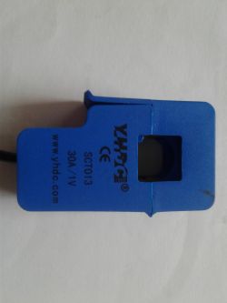
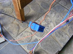
This sensor is called "Dietz clamp", i.e. it is easier to say that it is an ordinary transformer, but there is no primary winding in it, there is only a secondary winding, and the core of this transformer is divided, so you can fasten it with a cord non-invasively.
The primary winding will be a wire on which the sensor core will be fastened.
When using this sensor, a certain rule must be followed - the same as when using clamp meters - i.e. both this sensor and the clamp meter are fastened to only one of the power cables. In the case of fastening it with two wires supplying the device (phase and neutral wire), our sensor will usually show that no current flows through the wire, because as you know - the current in these wires flows in opposite directions and their sum will be zero.
What is inside our sensor - not much.
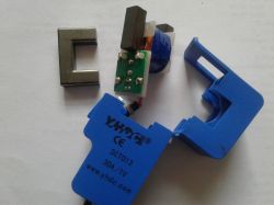
As I wrote above - we have a secondary winding with the number of turns 1800, a split core, a PCB, where the ends of the coil winding are connected and a resistor soldered between them. In this case it is a 62? resistor, on which we will measure our voltage from the sensor. For this one-meter cable terminated with a mini Jack plug.
The "gear" of our sensor is 30/1, i.e. at 30A, the voltage of 1VAC will appear on the sensor plug.
As the ratio of our sensor is 1: 1800, a current of 30 / (1/1800) = 0.01666A will flow through the secondary winding at 30A. The sensor has a built-in 62? resistor, so from Ohm's law we can calculate that at 30A, 0.01666 * 62 = 1.033V will appear on the sensor plug
Now we know why the manufacturer gives the information 30A / 1V on the housing.
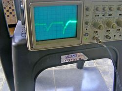
Below are some measurements using this sensor.
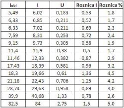
Here is a graph of the relationship between the measured current and the voltage appearing on the sensor plug.
The blue line is our sensor measurement, the green line graph pattern.
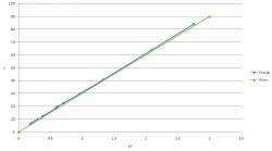
As you can see - the graph is almost linear and its deviation is not too large from the standard.
The table also includes the calculated current based on the voltage reading and the percentage error. Here we see a maximum deviation of 5% between what the clamp meter showed and what came out of the voltage-to-current conversion.
I used a clamp meter for the measurement, so you can't take these results literally.
As you can see - in a fairly simple way, it is possible to make a non-invasive current measurement in a cheap way, if we do not care about high accuracy.
This is how cheap clamp meters work, where we can only measure alternating current. Unfortunately, this sensor is not suitable for measuring direct current and in this case you need to use a sensor that uses the Hall effect, e.g. ACS712.
On Google you can find several examples of connecting this sensor to Arduino with a ready-made program.
As you can see, in a fairly cheap way (about PLN 30) we can build our own measuring clamps for measuring alternating current. We can also choose different variants of the CST013 sensor - versions are available: 5A, 10A, 15A, 20A, 30A or 100A, but it should be taken into account that the 100A version does not have a built-in resistor.
In the appendix, the specification of the sensor described here.
Below is a description of the sensor for non-invasive current measurement up to 30A.
The sensor can be purchased on Chinese auction portals together with the shipment at a price from about $ 4.5 or on Polish auction portals from about PLN 25 with the shipment.

This sensor is called "Dietz clamp", i.e. it is easier to say that it is an ordinary transformer, but there is no primary winding in it, there is only a secondary winding, and the core of this transformer is divided, so you can fasten it with a cord non-invasively.
The primary winding will be a wire on which the sensor core will be fastened.
When using this sensor, a certain rule must be followed - the same as when using clamp meters - i.e. both this sensor and the clamp meter are fastened to only one of the power cables. In the case of fastening it with two wires supplying the device (phase and neutral wire), our sensor will usually show that no current flows through the wire, because as you know - the current in these wires flows in opposite directions and their sum will be zero.
What is inside our sensor - not much.

As I wrote above - we have a secondary winding with the number of turns 1800, a split core, a PCB, where the ends of the coil winding are connected and a resistor soldered between them. In this case it is a 62? resistor, on which we will measure our voltage from the sensor. For this one-meter cable terminated with a mini Jack plug.
The "gear" of our sensor is 30/1, i.e. at 30A, the voltage of 1VAC will appear on the sensor plug.
As the ratio of our sensor is 1: 1800, a current of 30 / (1/1800) = 0.01666A will flow through the secondary winding at 30A. The sensor has a built-in 62? resistor, so from Ohm's law we can calculate that at 30A, 0.01666 * 62 = 1.033V will appear on the sensor plug
Now we know why the manufacturer gives the information 30A / 1V on the housing.
Below are some measurements using this sensor.

Here is a graph of the relationship between the measured current and the voltage appearing on the sensor plug.
The blue line is our sensor measurement, the green line graph pattern.

As you can see - the graph is almost linear and its deviation is not too large from the standard.
The table also includes the calculated current based on the voltage reading and the percentage error. Here we see a maximum deviation of 5% between what the clamp meter showed and what came out of the voltage-to-current conversion.
I used a clamp meter for the measurement, so you can't take these results literally.
As you can see - in a fairly simple way, it is possible to make a non-invasive current measurement in a cheap way, if we do not care about high accuracy.
This is how cheap clamp meters work, where we can only measure alternating current. Unfortunately, this sensor is not suitable for measuring direct current and in this case you need to use a sensor that uses the Hall effect, e.g. ACS712.
On Google you can find several examples of connecting this sensor to Arduino with a ready-made program.
As you can see, in a fairly cheap way (about PLN 30) we can build our own measuring clamps for measuring alternating current. We can also choose different variants of the CST013 sensor - versions are available: 5A, 10A, 15A, 20A, 30A or 100A, but it should be taken into account that the 100A version does not have a built-in resistor.
In the appendix, the specification of the sensor described here.
Cool? Ranking DIY


