I am again, my beloved readers. And this is thanks to quite a large package that I recently received from Kamil. But about this, you could read in a separate
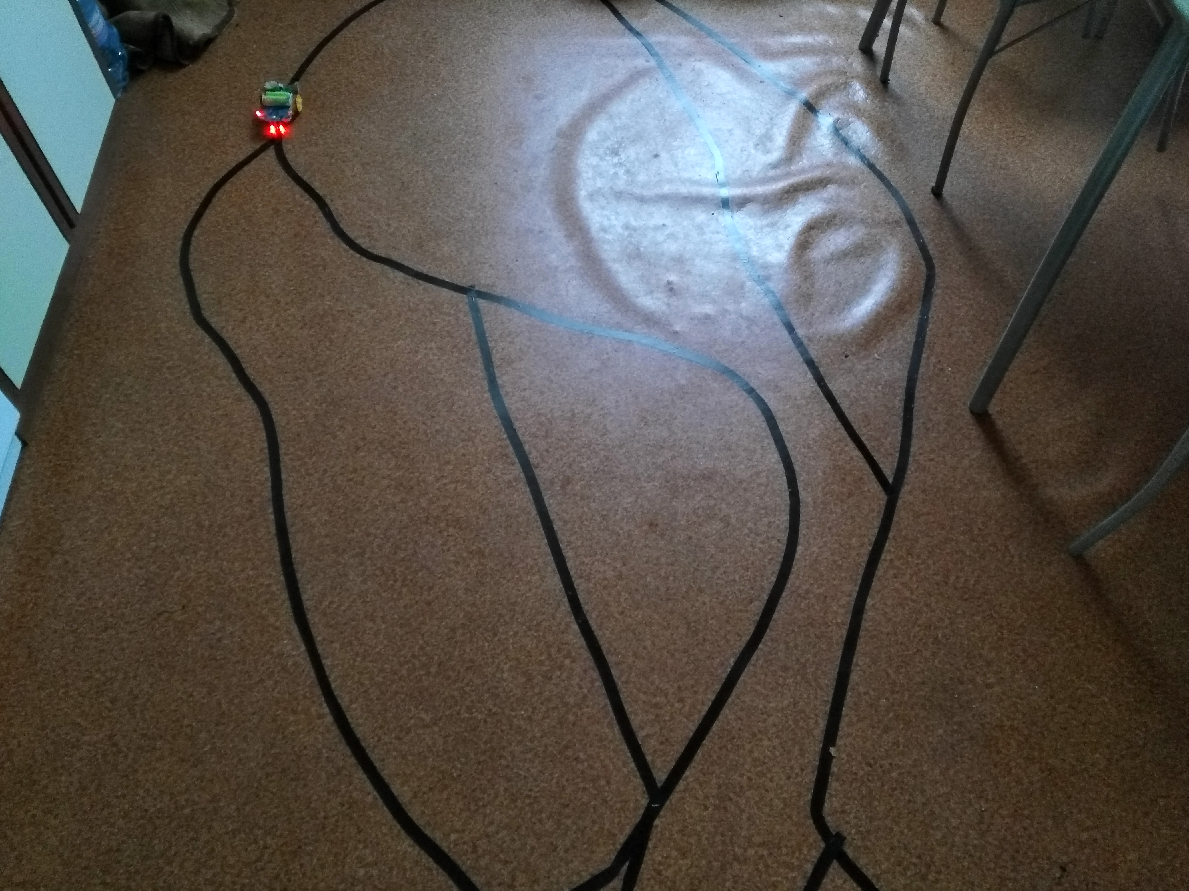
subject This time I will present you a toy that I was very skeptical about. Because who and why would buy it and admire this "invention"? However, after I put it together and started it, I started laughing like a child. Immediately afterwards, when I released him on the table at work, it turned out that this gadget not only makes me laugh. And when I took it home and showed it to my Emi, a moment later, she was sitting on the kitchen floor with a roll of black electrical tape in her hand and pasting the routes. "Robocik called" her sweetie "and asked if she could keep him

. Ah, those women
.

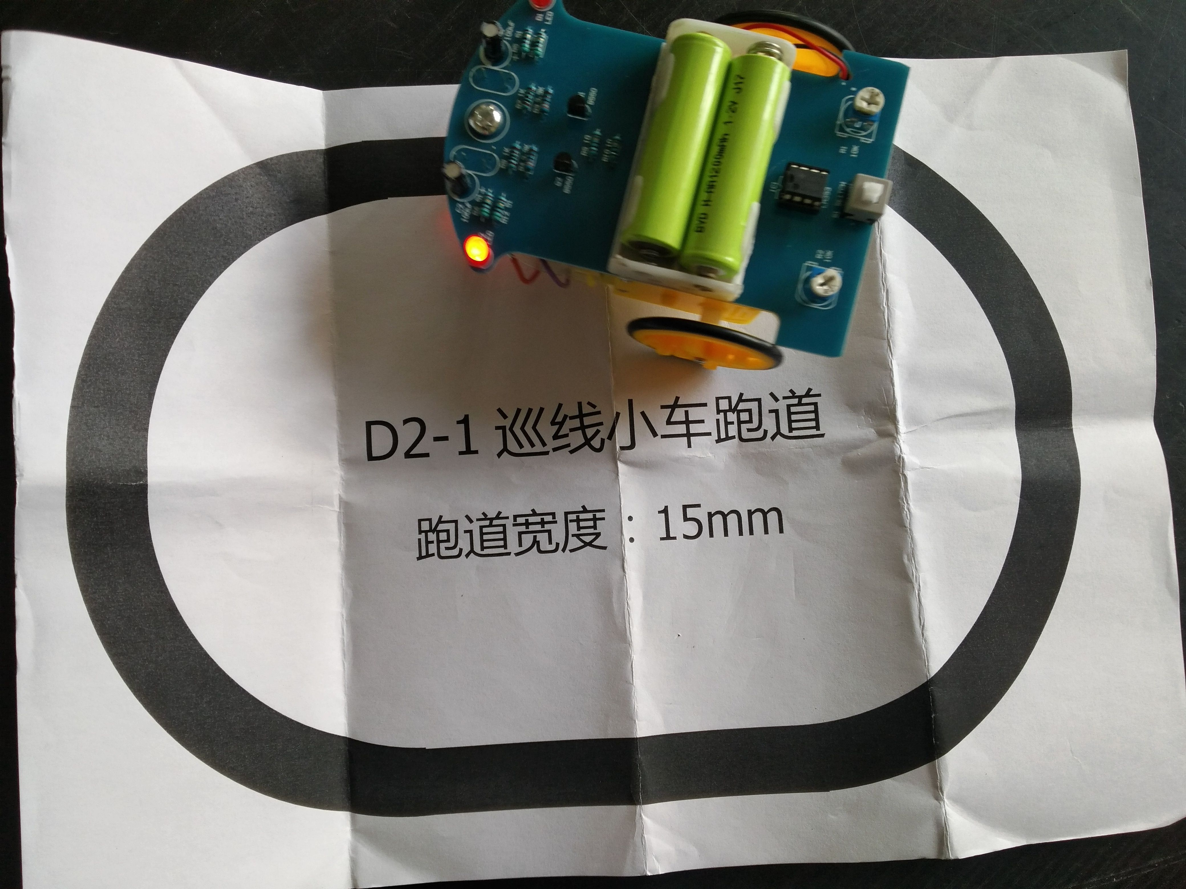
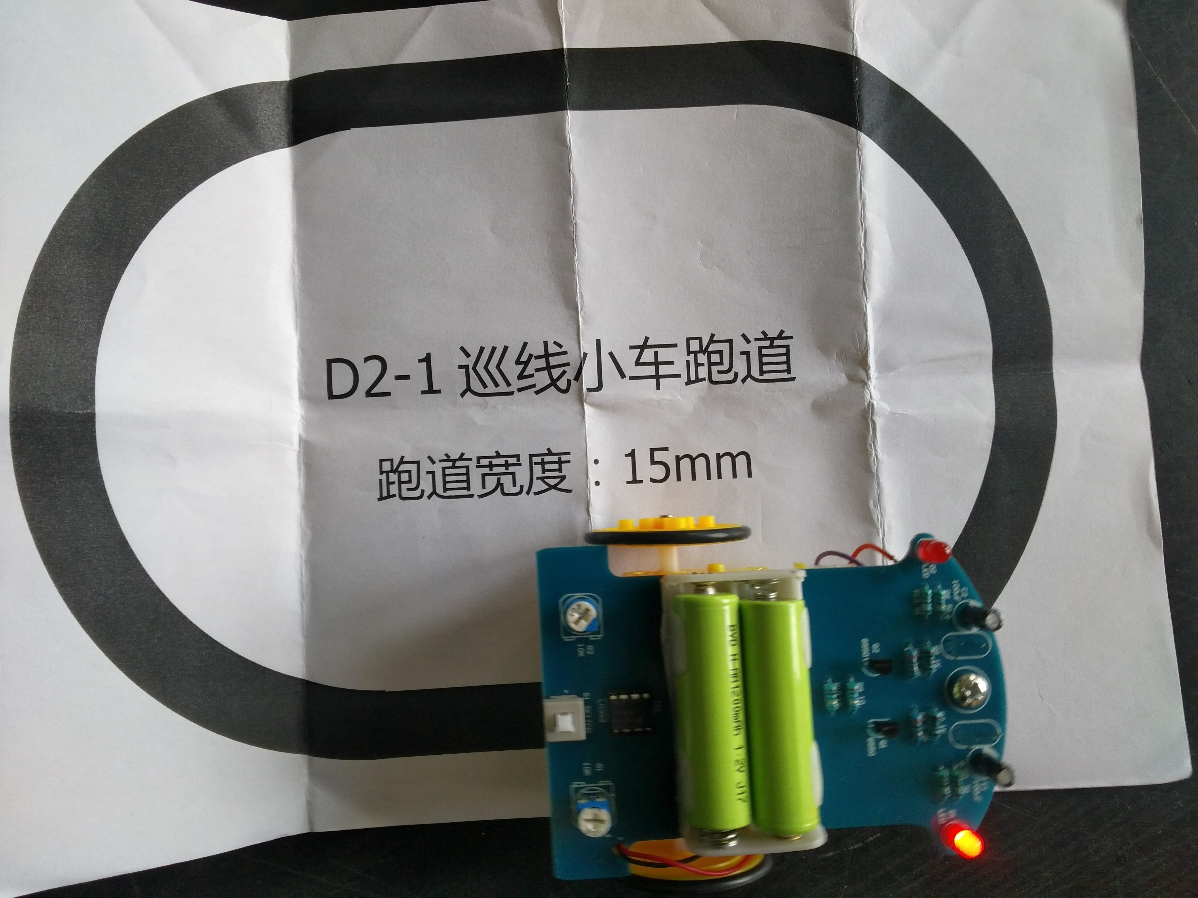
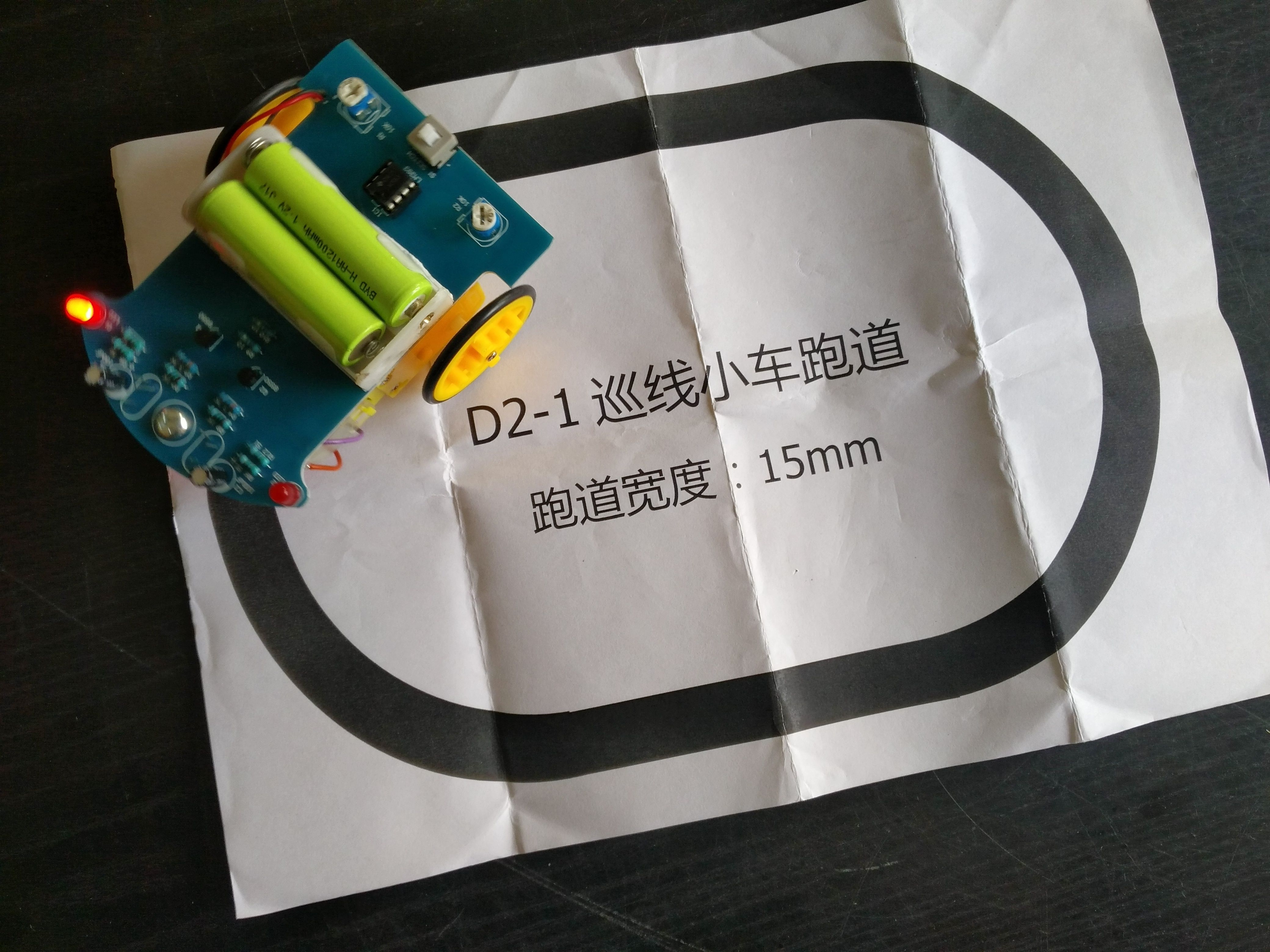
The toy is very simple in its construction. And as some young readers will probably be surprised, it does not have any microcontroller in its structure. And yet, it is very good at moving along the designated line.
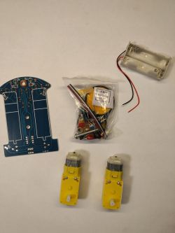
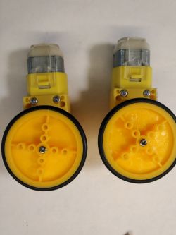
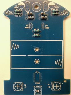
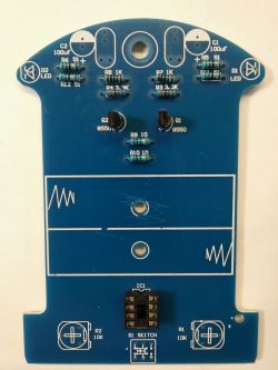
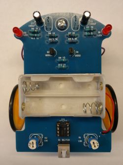
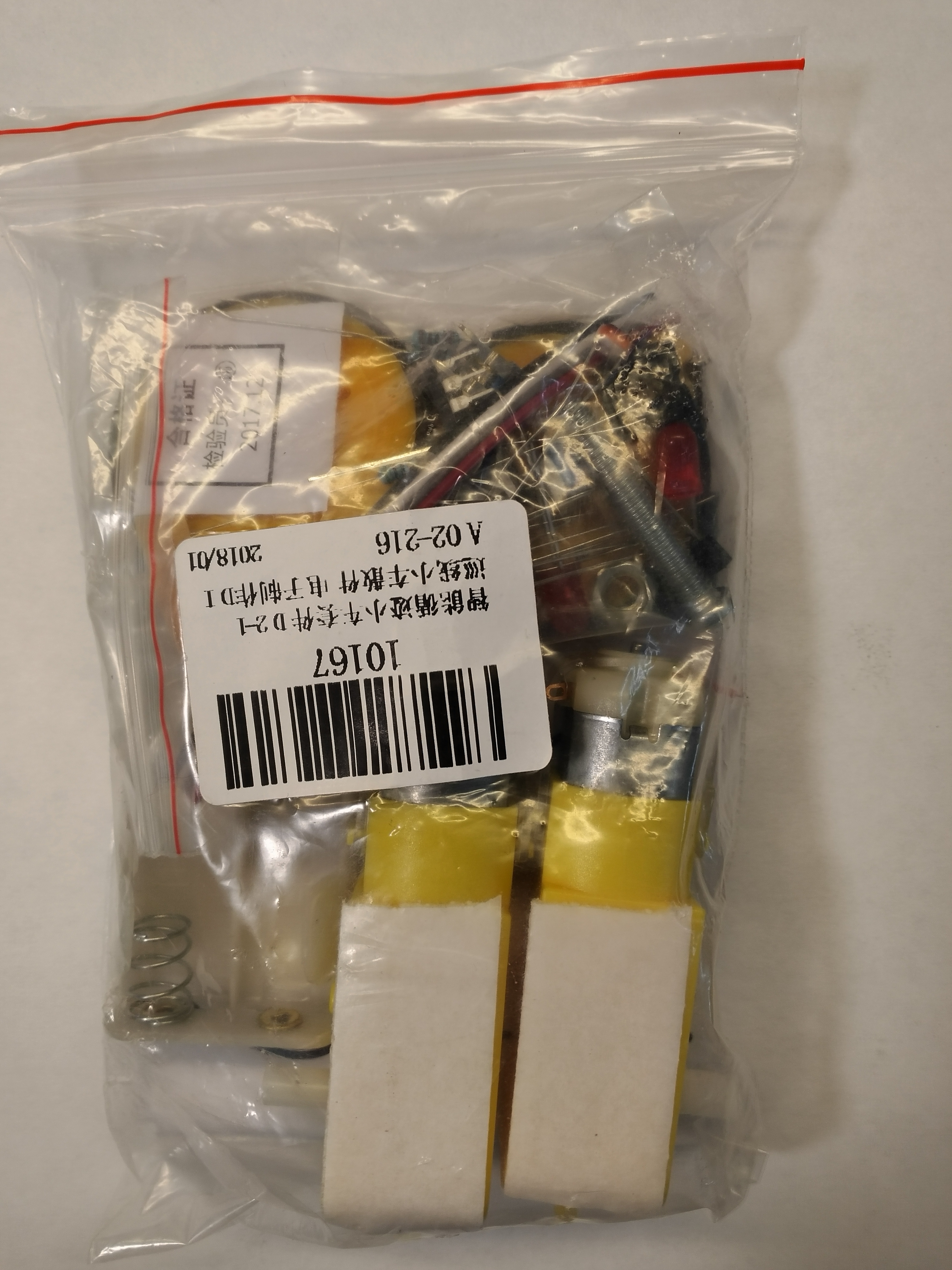
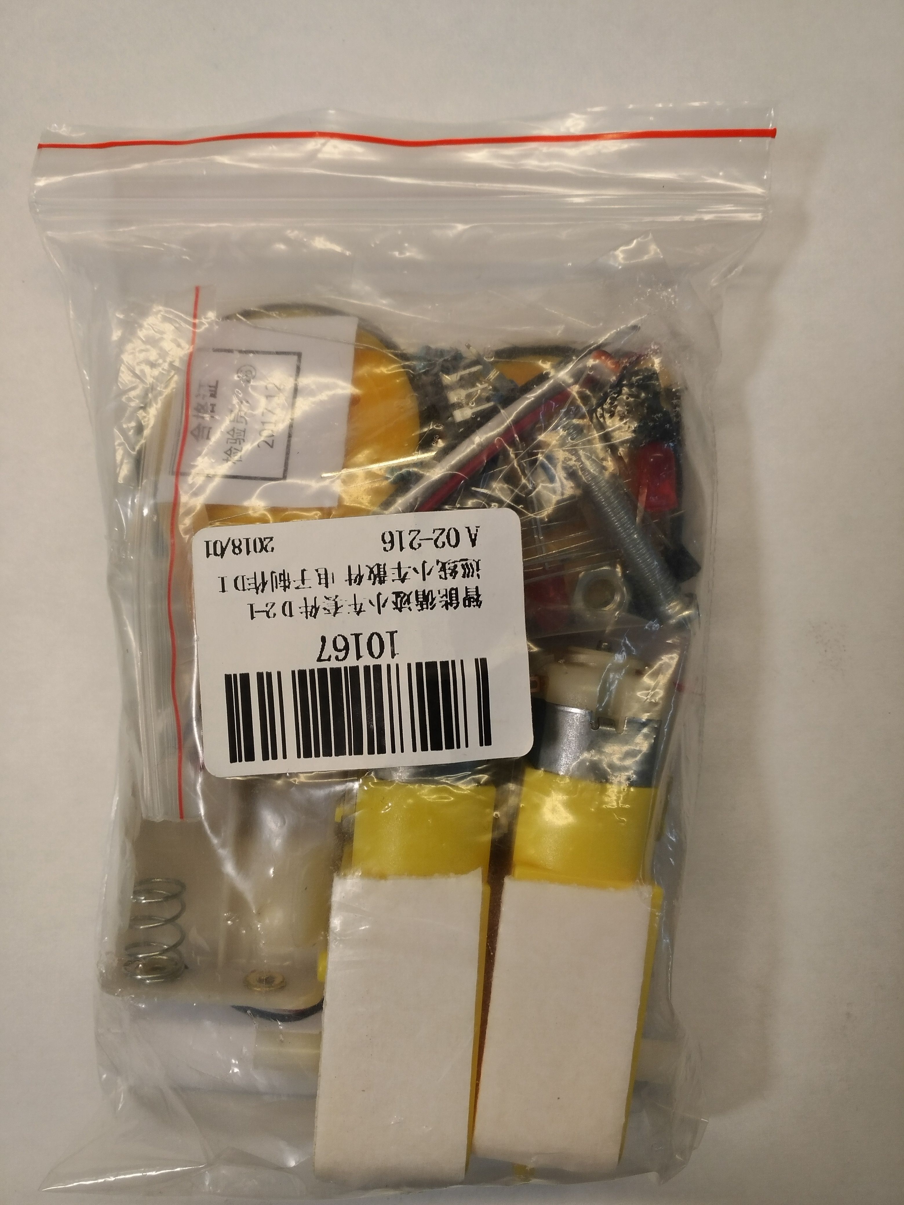
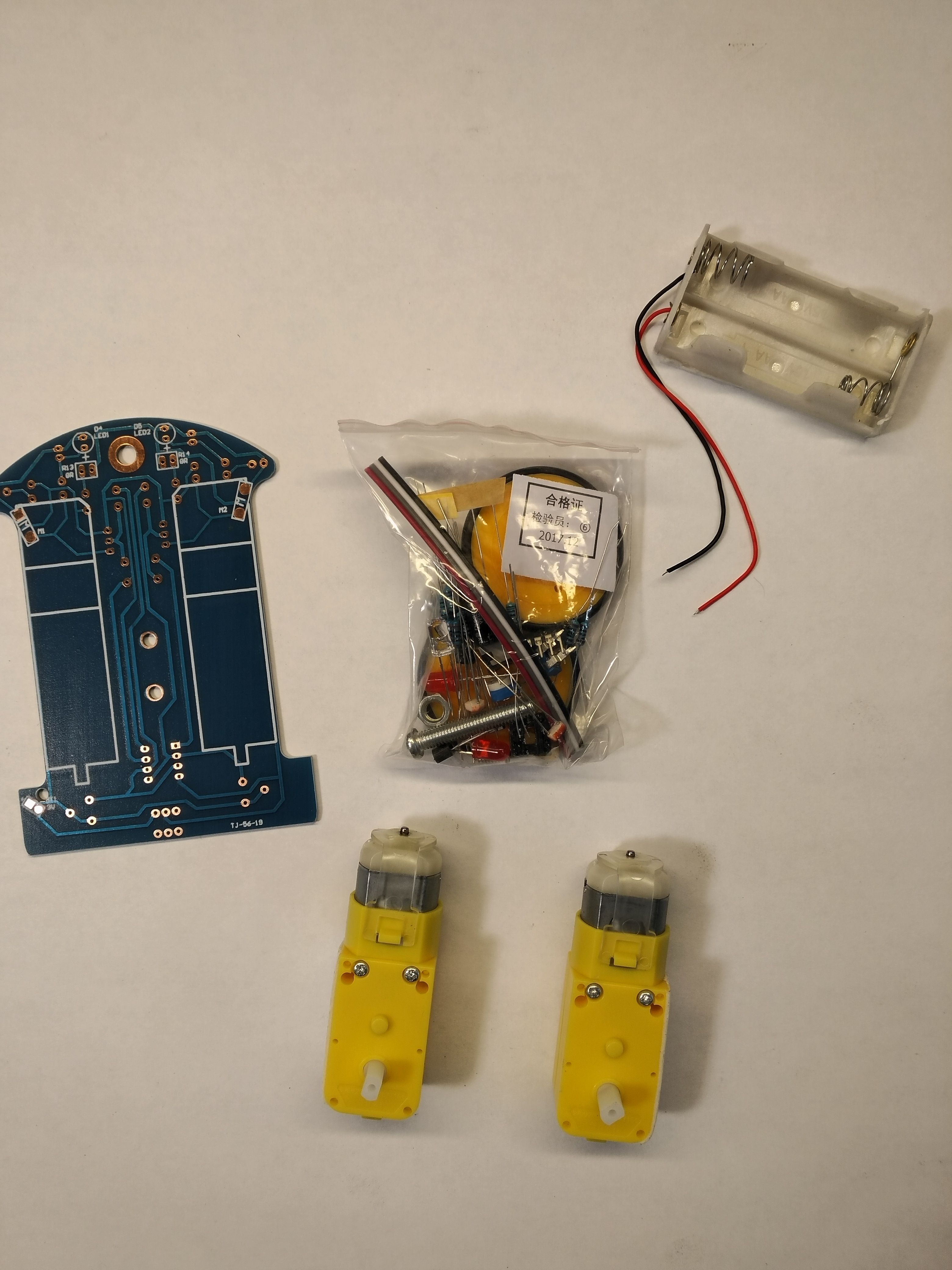
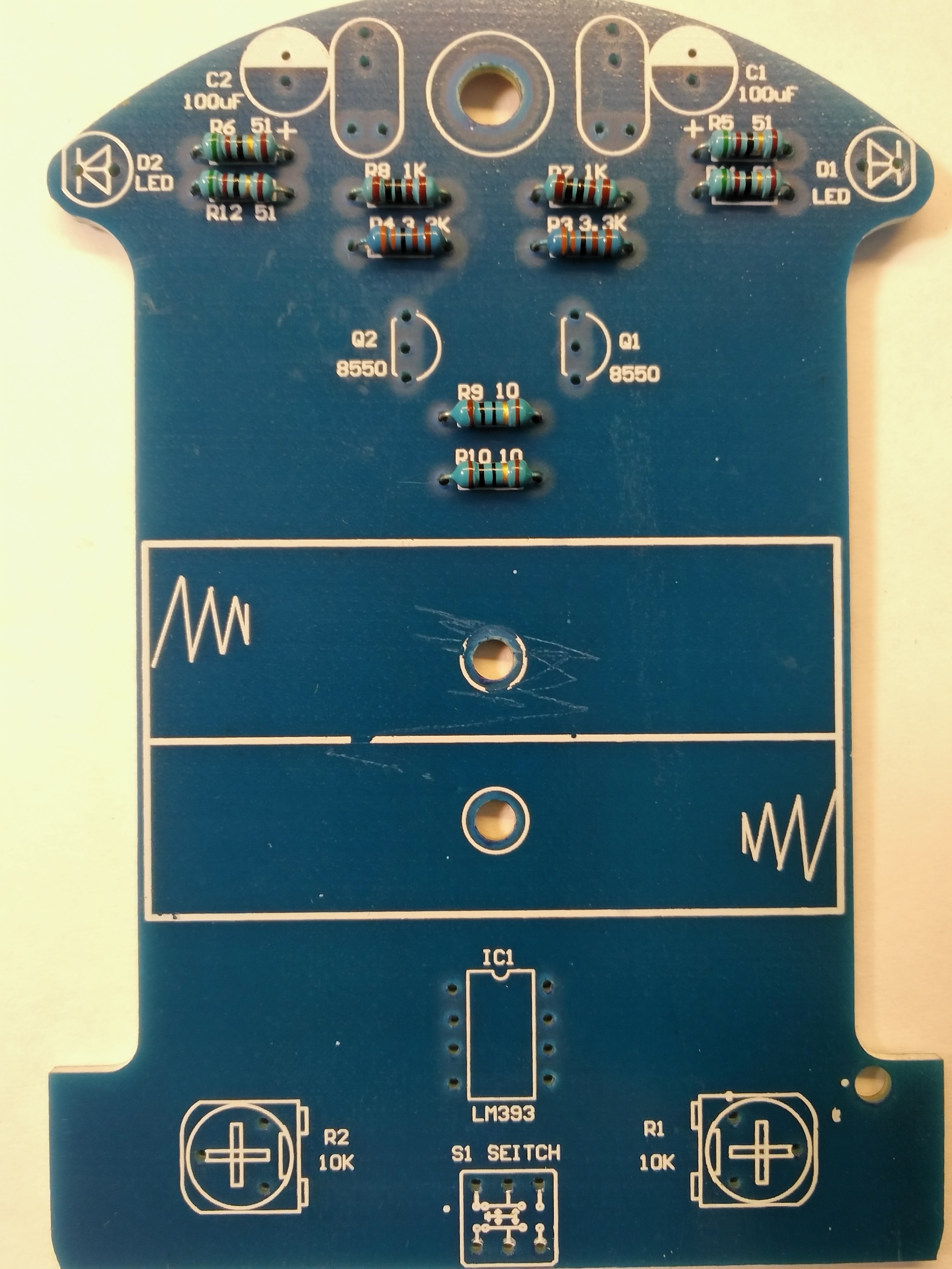
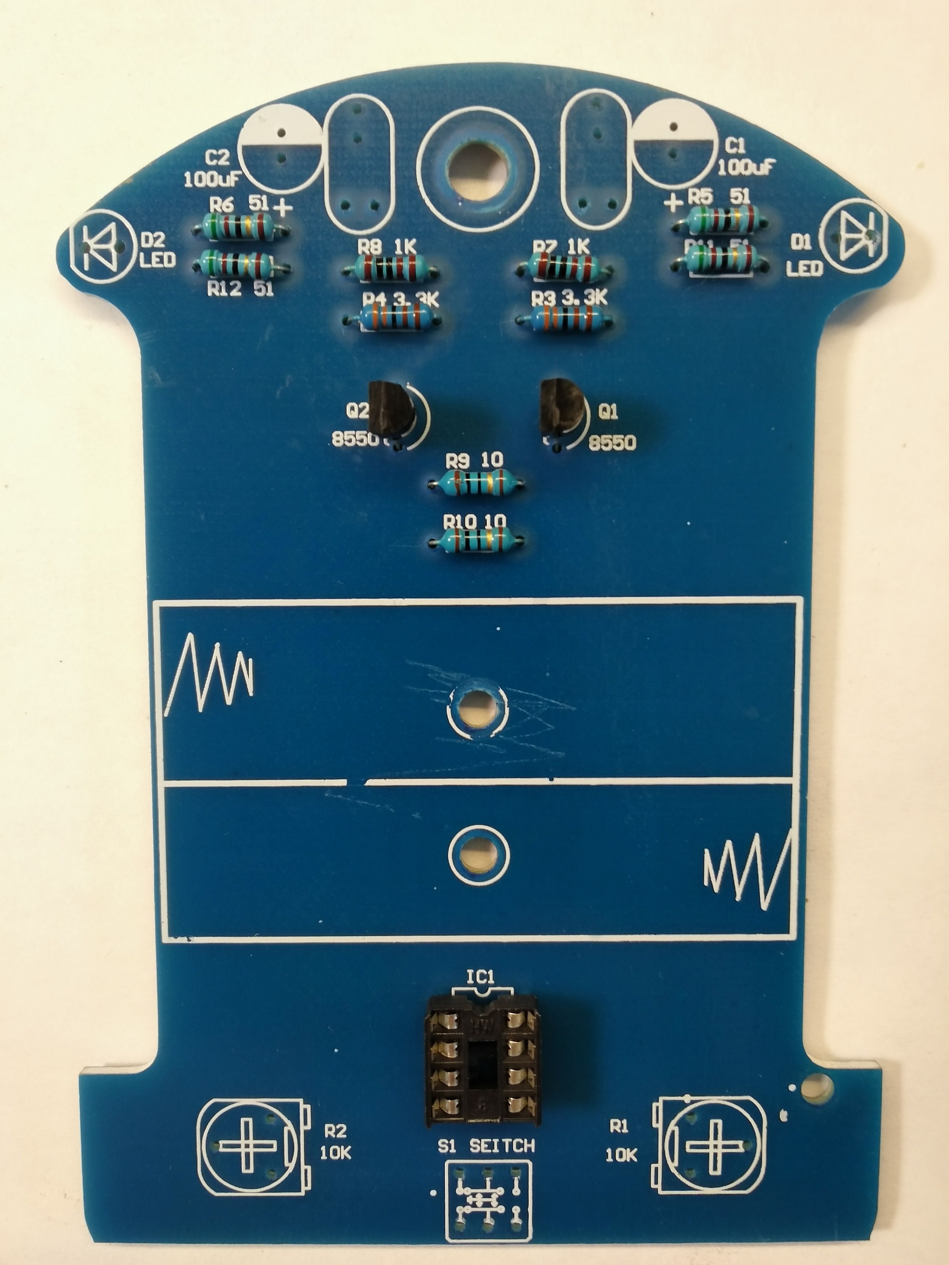
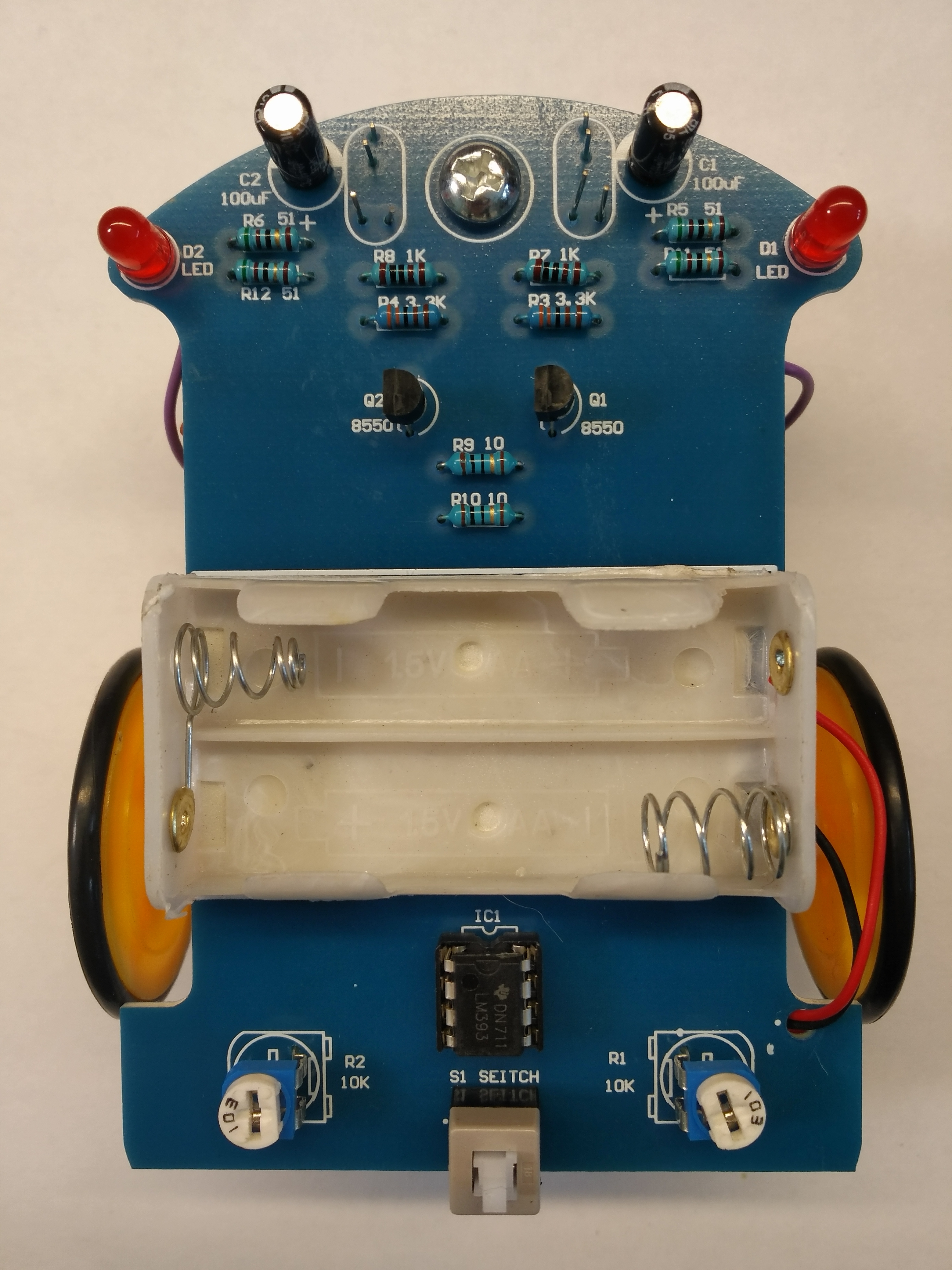
What we get in the set, you can see in the photos below:
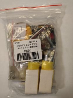
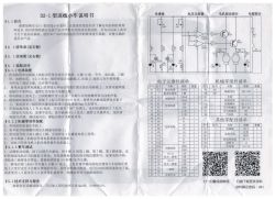
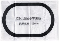
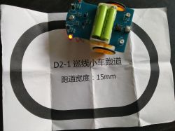
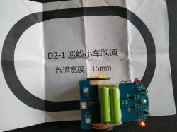
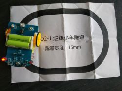
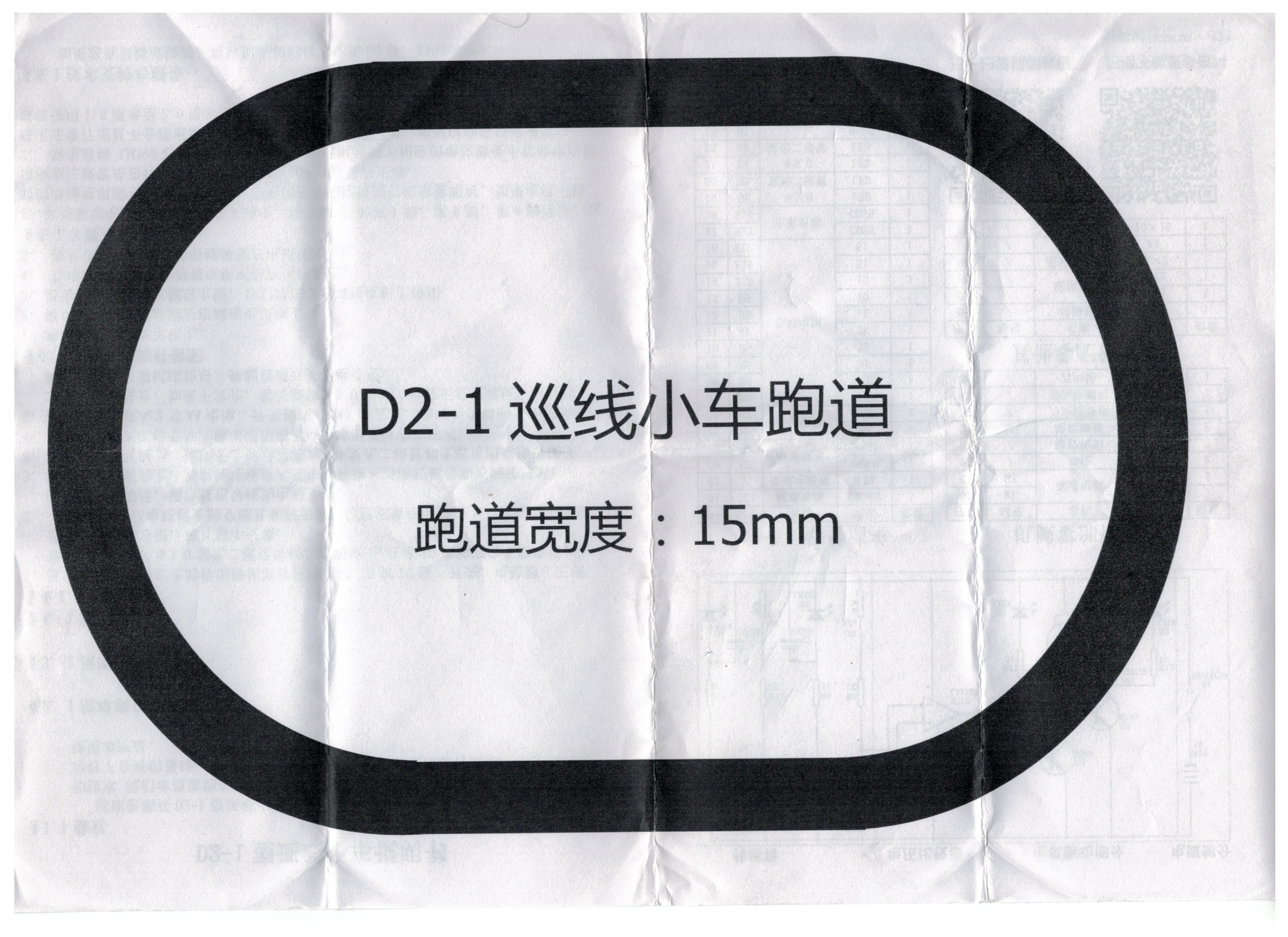
There is even a schematic and a "test track".
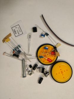
The set includes:
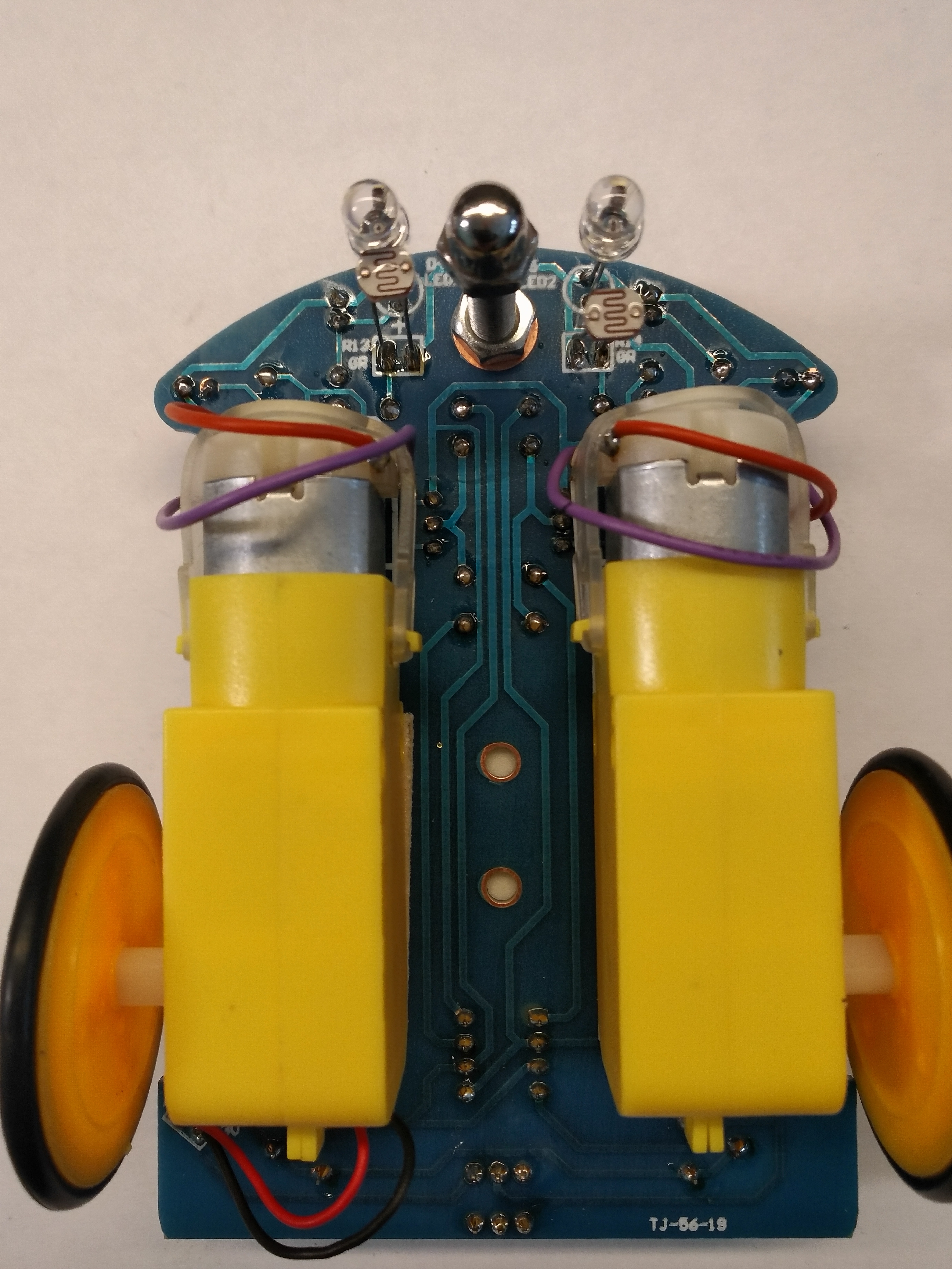
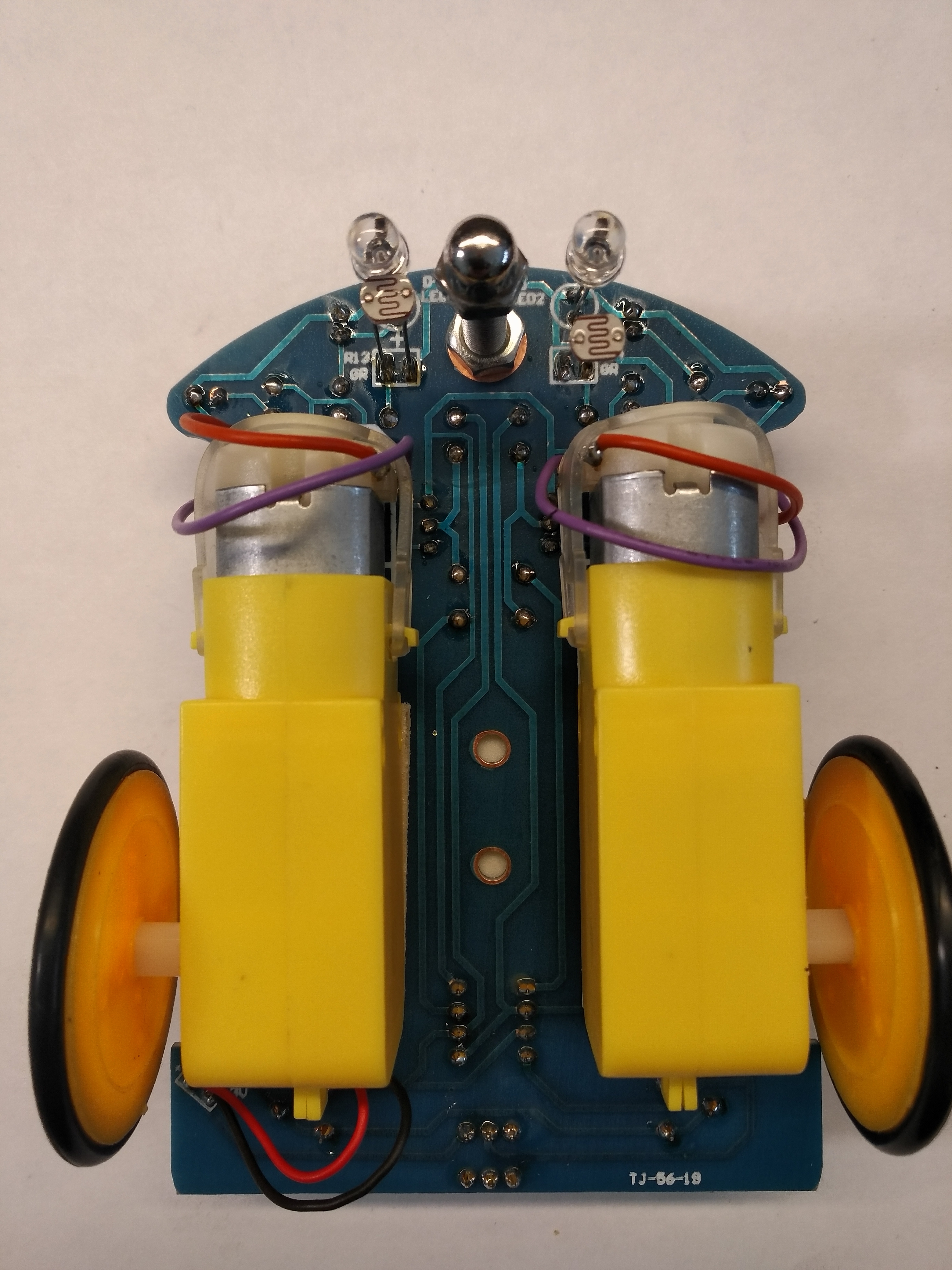
1. Two geared motors. They are glued with double-sided foam tape, which allows them to be quickly mounted to the PCB.
2. Two wheels, with "tires", and screws to screw them to the axles of the motors.
3. LM393 double operational amplifier and a socket for it.
4. Basket for two AA batteries. Stuck with double-sided adhesive tape.
5. Switch button S1.
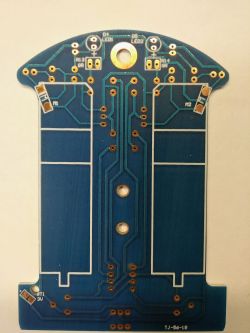
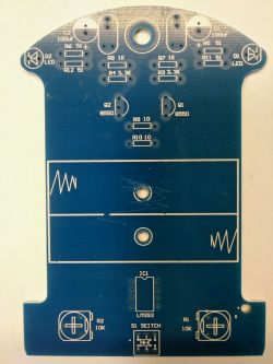
6. The PCB which is also the supporting structure of the whole "robot".
7. Two bright red LEDs in transparent housings. Cooperating with photoresistors.
8. Two red LEDs in diffusion casings. Facilitating system adjustment.
9. Two photoresistors. Acting in conjunction with bright LEDs, functions of sensors.
10. Two 10kOhm mounting potentiometers. To adjust the system.
11. Two 8550 transistors as drivers for the motors.
12. Ten resistors with different values.
13. Two electrolytic capacitors 100uF / 25V
14. M4 screw with a decorative nut, with a rounded head. It functions as a third wheel, and that is a very weak solution.
The system consumes 35mA at a voltage of 3V.
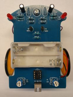


The system is very easy to assemble. As always, start with the lowest elements. It also suggests that you solder the wires to the pins on the motors before sticking everything together with double-sided tape.
I must say that with this DIY Kit, I am very pleased. This is a gadget that can really teach you a lot and show that you can do something interesting on discrete components (apart from the integrated op-amp), without using the ubiquitous microcontrollers.
The attached diagram will allow even very beginner electronics to understand the principle of operation of this gadget. Those slightly more advanced should understand it without even looking at this banal pattern.
Summarizing. I believe that if someone wants to learn something and build a toy that will make many people smile, then this gadget is a bull's eye.
If someone likes to combine, you can experiment with different LEDs that work with photoresistors. Can you change them to infrared (IR) and see what happens, will the photoresistor react at all, to this band? Or maybe ultraviolet (UV) diodes and mark the route so that it is visible only to our robot. Then just dress him up in a stuffed rat or some spider and you can get your mother-in-law's number
sesese ...
Best regards.
CMS


Comments
The gadget I took casually turned out to be a great entertainment module. If someone has children, it can guarantee fun for long hours associated with the assembly itself, pasting the path by observing... [Read more]
In my opinion, the best of the tested putties so far. [Read more]
Maybe that's why? Comparator based circuit I suppose? I did something similar once (also) for entertainment purposes. Somewhere else it lies in the junk ... As for marking the route with tape - I... [Read more]
Hello, I have to admit that I bought this car in December for children, but it has not been launched yet. It is soldered, only to insert the batteries. I wonder what to replace this screw with to make... [Read more]
This nut is a failure, when the insulation on the bends wrinkles, it gets stuck in these places. That's why in the video it's weighed down with stones (I stole from a flower). I think that if you... [Read more]
Oh no! This CMS again! You open the fridge and there he and his Chinese toys ... Just a joke ;) . A no-nonsense idea may be ... A LEGO brick circle. Back in the day, in the SYSTEM series with aircraft,... [Read more]
I have this kit and I confirm, a small simple thing, and it enjoys. As for the screw, the more "professional" LineFollower designs use support balls, e.g .: https://obrazki.elektroda.pl/8181283700_1525164618_thumb.jpg... [Read more]
@CMS thank you for the reviews of the future toy for my grandson. I hope I can play with it. [Read more]
I feel like Grandpa will have more fun :) . [Read more]
I know this topic for a good quarter of a century :-) On this principle, I used to service an automatic acetylene burner for cutting steel sheets and plates. Although in the beginning of the 90s, the... [Read more]