Several days before my wedding I came up with an idea to rent a photo booth for a wedding party. When I saw what the rental prices are, I quickly decided that I would do my own, because the cost of building it was close to the cost of renting a photo booth for 2-3 hours. By the way, I recorded some material for my YT channel (
JestemInzynieremPL).
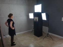
My photo booth design consisted of a digital camera, monitor and Arduino board, without a printer. Printed photos in the ubiquitous times of socialmedia are rather outdated, because everyone prefers a photo for a fejsika rather than a small printout. What's more, from the designer's point of view a photo booth, omitting a printer is a very good idea, because it greatly simplifies its construction. And it reduces its price. And the cost of operation.
Most cameras have a miniHDMI output, which can be used to send the image directly to the monitor. In older monitors, there is not always an HDMI socket, then you must use adapters for DVI or D-SUB jacks. I did the photo booth at cost, so I have a used monitor and I am using the miniHDMi - D-SUB adapter. After connecting the camera, the image from the display appears on the monitor. The device must have a power supply with an adapter pretending to be a battery so that it can work for several hours or more.
I set the camera so that after taking each picture it would display the picture for a certain time. Ot all the magic of the photo booth. All I had to do was make an Arduino circuit based layout that triggered the shutter of the camera after pressing the 'take a picture' button.
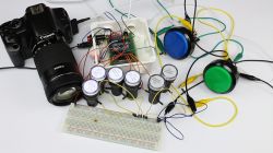
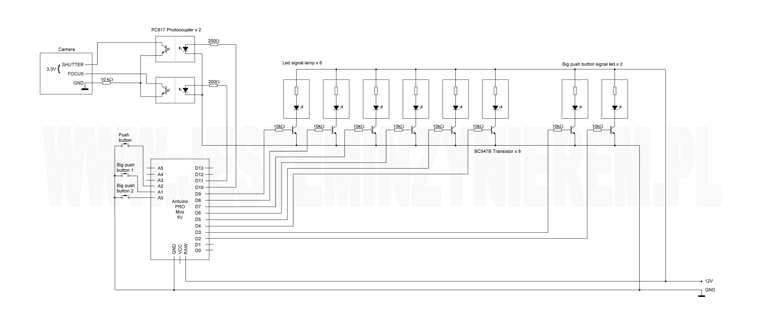
The camera's photo control system is based on the Arduino PRO Mini in the 5V version. I also used the construction of the device: 6 pcs. 12V signal lamps, 2 large buttons with backlight, one tact-switch button, LED, ON-OFF round switch, DC 12V socket, resistors with 200 Ohm and 10KOhm resistance, 2 optocouplers, 8 NPN transistors, prototype board, female goldpin strips and male, 2.5mm micro-jack, 4 nylon spacers and plastic housing.
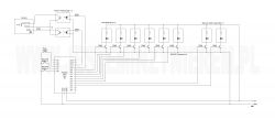
The scheme of the photo booth control system is very simple. The explanation may start with the fact that the whole is powered by 12V DC. There is a good option, because all elements of the system can be supplied with the same voltage.
As I mentioned before, the fotobudka is controlled by the Arduino PRO Mini board with 5V logic. All peripherals are connected to it. The power supply to the PCB is fed to the RAW pin, GND ground. Two big front buttons and one small one, placed on the controller's casing, give the possibility of triggering the shutter from the inside of the photo booth connected to pins A0, A1, A2. From the pin D2 to the pin D9, the signaling and high key backlight are connected. Pins D10 and D11 are connected to the camera.
Of course, the camera is not connected directly to the Arduino, because both devices have different operating voltage & # 8211; 3,3V camera, and Arduino 5V. Additionally, it is worth taking care of the camera's safety and electronically separating the Arduino camera system using an optocoupler. With this solution, for a zloty I have such protection that I can connect up to 1000V and nothing should happen with the camera.
The control system is connected to the camera via the cable inlet. This is a 2.5mm micro-jack. Proper shorting of the pins of the camera's socket allows you to imitate pressing the shutter release button.
These are now signal lamps. I admit that I do not know exactly what is in them, but I bet that some LED and resistor. The most important is that they are powered by 12V electricity, i.e. they can not be directly connected to Arduino. And here transistors come in with help.
The entire assembly of electronics, explanation of the scheme, operation algorithm and sketch of the control program can be seen in the following video:
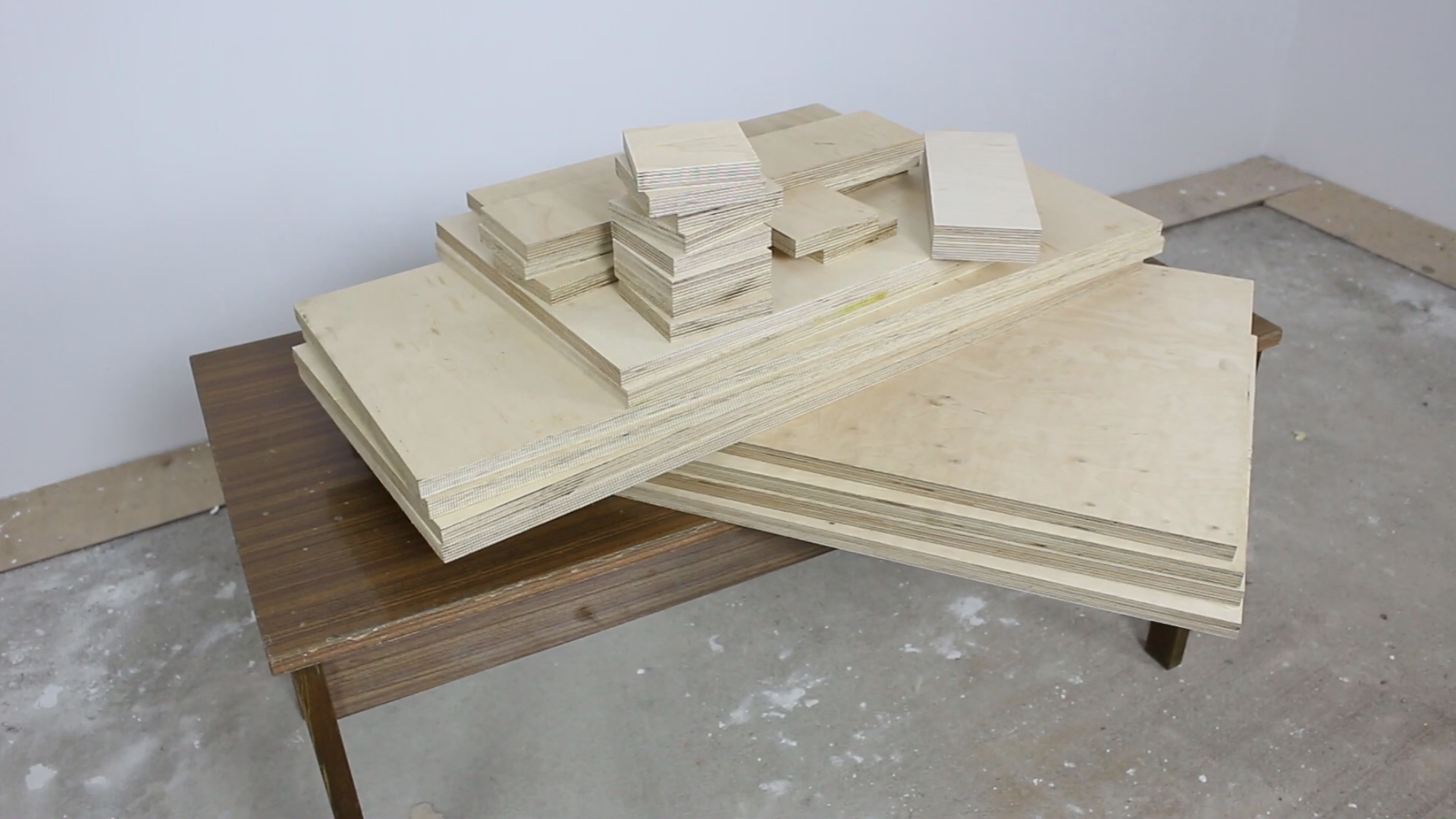
I started the construction of the photo booth body by cutting the plywood. I can give you advice so that you do not let her alone in the DIY store. Most large DIY stores have such great, great saws on which they cut the plates to the nearest millimeter. I was very pleased, all the boards were cut evenly and precisely.

I will immediately admit that I do not have much in common with woodwork, so it's possible that I made mistakes that seem blatant to those involved in this profession. If so, I would like to read your comments and comments.
Below is a video on which I am describing the construction of the body and showing the work of the photo booth:
At the end, a small summary: fotobudka is doing very well, she has already worked over a dozen events after 8-10 hours of uninterrupted work. I am very pleased with it, although there are a few things that I would change and improve in the construction of the next one. Maybe you have any questions or tips? I'm happy to discuss, but not in the style of Arduino? A real engineer does not tick it.
I bet that entering a link to the site with photo gallery taken by the photo booth will be treated as a prohibited advertisement? If not, I would like to praise


Comments
What model of Canon do you use? [Read more]
Canon 700D [Read more]
I admire my friend that a couple of days before my wedding had time and permission from (then future) wife to fight this construction :) [Read more]
The second time I would not have taken up in such a short time, because the last work on the photo booth ended the day before the wedding :-D [Read more]
Respect for taking up the challenge a few days before the wedding. I'm asking a few questions: - softboxes shine all the time? What is the source of light in them? - is this added lighting enough to... [Read more]
Yes, softboxes have a candle all the time. There are 5500K solid light bulbs in the lamps. I'm thinking about adding a flash, because it happens that "dynamic" pictures are sometimes disturbed. Yes,... [Read more]
Hello, great idea! Do you have the sizes of plywood you wrote down that you ordered in the shop for cutting? [Read more]
Thanks! The body was made of 18 mm thick plywood, I used panels with the following dimensions: 2 items - 868 x 500 mm 2 items - 850 x 500 mm 4 items - 850 x 350 mm 2 items - 500 x 368 mm 2 items -... [Read more]
Revelation! Especially for creativity and the deadline for implementation :) In the end something different than the amplifier, power supply or Tesla coil;) [Read more]
If manual sharpening, light permanently, writing on the card, why the arduino? [Read more]
In total, it's enough to set the self-timer on the camera, the button from the trigger and the monitor: D [Read more]
Arduino probably basically serves only to light up the lights, which count down the time to take off (and replace the self-timer). It looks like shooting a cannon to a sparrow, but in my opinion it is... [Read more]
to your questions, Artwa replied roughly: Using Arduino to trigger the shutter of the camera gives you much more control over the whole. I can freely set the time and number of photos taken "at... [Read more]
This paste into the first post, without it, just a few meters of two-wire cable, monostable button and a dedicated plug for the camera, with me just 2.5mm Jack. Before this type of events, quite interesting... [Read more]
From the experience I have gained, it is necessary to use as few cables as necessary to operate the photo booth. Drunk people can do a good shit :-D And that's btw. I do not know why such an aversion... [Read more]
BRAVO! Congratulations on the occasion of the wedding and the idea! Maybe other colleagues were having fun in this idea? I have a few ideas and I will try to present them in a few weeks. gre... [Read more]
I agree with you exactly. Why use 2 integrated circuits, if one processor can be used? And instead of an independent processor - PRO Mini, which was created just to use it in ready-made solutions. The... [Read more]
What type of camera did you use? Some of the Canons had the ability to control the USB - you could both release the shutter and set some exposure parameters. Of course, you can also transfer photos, and... [Read more]
# 3 [Read more]