An $8 electronic load module lets you test power supplies by forcing a controlled current instead of using bulbs, resistors, or a bare transistor on a heatsink.
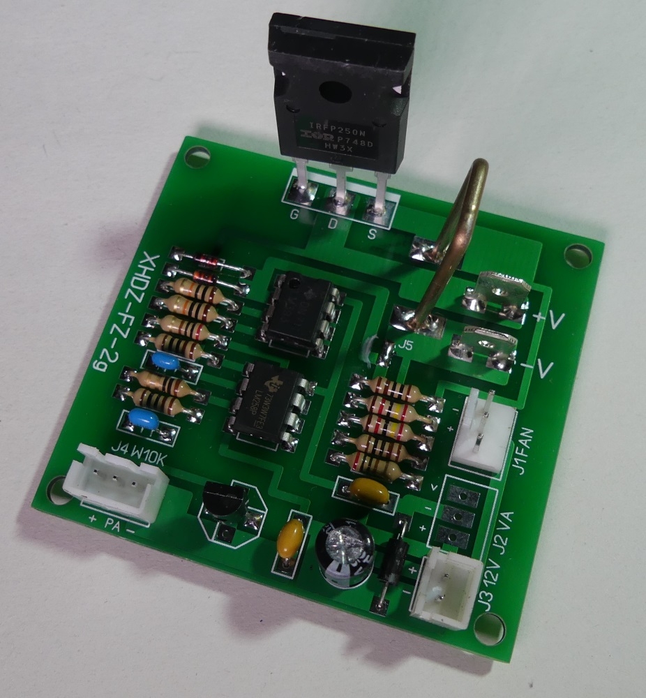
The board uses an IRFP250N, TL431, LM258, LM393, a bent-wire shunt resistor, a 5-20k potentiometer, and a 12V supply.
Auction specs claim 75W maximum power, 50W continuous power, 10A maximum current, and 100V maximum voltage.
To start it, mount the transistor on a heatsink with fan, connect the load terminals in series with an ammeter, and feed 12V into J3.
The 50W continuous rating is lower than the 75W peak rating, so cooling is critical during use.
Summary generated by AI based on the discussion content.
When testing, for example, power supplies, an electronic load is useful to, for example, force the flow of a specific current. In practice, light bulbs are often used quickly (which is a bad solution due to the low resistance of the cold fiber), resistors, or a random transistor on the heatsink, the base or gate of the transistor is controlled by an operational amplifier, or often without a feedback loop with an ordinary potentiometer. It is available on auction portals electronic load module priced ~ $ 8. In the description of the auction, we see the following parameters: maximum power 75W, continuous power 50W, maximum current 10A, maximum voltage 100V. On the board, we see a measuring resistor (in the form of a bent wire), a transistor IRFP250N, TL431, LM258, LM393. To start the artificial load, mount the transistor on a heat sink (preferably equipped with a fan), attach a 5-20k potentiometer ensuring current regulation, and connect a 12V power source.
The V- V + connector is used to connect the cables connecting the tested device, in series in this circuit it is worth to turn on the ammeter to control the set current. The 12V power supply is supplied to the J3 connector, the device consumes a current
About Author
TechEkspert wrote 7212 posts with
rating 5583 , helped 16 times.
Been with us since 2014 year.
I have such, DIY:
https://www.elektroda.pl/rtvforum/viewtopic.php?p=14988589#14988589
Maybe you have a schematic for the reviewed copy, I wonder if there will be big differences,
I also did it on a... [Read more]
TechEkspert
29 Aug 2018 20:35
There is no scheme, the description of the auction is usually tragic, this is a common feature of these cheap modules ...
It is important that it works :) and does not generate oscillations ...
The... [Read more]
tplewa
29 Aug 2018 22:20
@TechEkspert
Let's take a look at the IRFP250N and take into account that in this system it works in DC mode ... unfortunately, the documentation does not often provide SOA for DC mode ... but... [Read more]
_johnny_
30 Aug 2018 16:47
IGBT transistors are best suited for dissipating DC power. They have a much wider ch-ke SOA, so you can lose up to 300W in a housing like the transistor above. [Read more]
tplewa
30 Aug 2018 19:57
They don't necessarily have to be IGBTs. Anyway, it's better to give more transistors - in fact, apart from the transistor, we have few elements, in total an operational amplifier and a measuring... [Read more]
maciej_333
04 Sep 2018 15:39
Found this pattern in less than a minute: Link . As you can see, someone took the trouble to draw it from a PCB. Who will now solve the puzzle related to the purpose of using the D1 diode and the threshold... [Read more]
jaroslawk
04 Sep 2018 19:26
Hello,
If I am not mistaken, the output of the R13 resistor should be connected to GND and not to V- and the system works from about 0.7V. [Read more]
TechEkspert
05 Sep 2018 18:53
This is the scheme, but in a place where someone did reverse engineering ... and not at the seller / manufacturer.
As for D1, this is a primitive way to get virtual mass? [Read more]
FAQ
TL;DR: A $8, 75 W load module delivers only about 50 W continuous, “These 75 W are even temporary” [Elektroda, tplewa, post #17412495] IRFP250N’s DC SOA drops below 20 W at 100 V. Why it matters: Knowing the real limits prevents MOSFET failure and saves test time.
1. What is the safe continuous power for the IRFP250N on this board?
Stay near 50 W with strong airflow. The DC safe-operating-area curve shows the transistor falls below 40 W at 50 V and <20 W at 100 V [IRFP250N Datasheet][Elektroda, tplewa, post #17412495]
2. Can the module run the advertised 75 W indefinitely?
At 50 W the MOSFET’s junction rises ≈62 °C above heat-sink temperature (RθJC 1.25 °C/W) [IRFP250N Datasheet]. Forced airflow keeps case temperature under 100 °C and prevents thermal runaway.
4. What does diode D1 do in the published schematic?
6. How do I wire the potentiometer for current control?
Connect the wiper to the op-amp non-inverting input. 2. Tie one end to 12 V, the other to ground. 3. Use 5 – 20 kΩ to cover 0–10 A range [Elektroda, TechEkspert, post #17412176]
7. How can I stop oscillations?
Keep wiring short, add a 100 nF ceramic across V+ / V−, and place a 1 µF capacitor across the sense resistor to slow the loop—“important that it works and does not generate oscillations” [Elektroda, TechEkspert, post #17412253]
Paralleling two MOSFETs halves current per device, doubling reliability. Balance with 0.1 Ω source resistors to avoid current hogging [Elektroda, tplewa, post #17414054]
10. What happens at 100 V and 1 A (100 W)?
The transistor exceeds its DC SOA; thermal stress can cause sudden die cracking—an observed failure mode in high-voltage loads [IRFP250N Datasheet].
11. How do I insert an ammeter correctly?
Break the V+ line from the supply. 2. Wire the meter in series between supply and V+ terminal. 3. Keep leads short to reduce inductance [Elektroda, TechEkspert, post #17412176]

Comments
I have such, DIY: https://www.elektroda.pl/rtvforum/viewtopic.php?p=14988589#14988589 Maybe you have a schematic for the reviewed copy, I wonder if there will be big differences, I also did it on a... [Read more]
There is no scheme, the description of the auction is usually tragic, this is a common feature of these cheap modules ... It is important that it works :) and does not generate oscillations ... The... [Read more]
@TechEkspert Let's take a look at the IRFP250N and take into account that in this system it works in DC mode ... unfortunately, the documentation does not often provide SOA for DC mode ... but... [Read more]
IGBT transistors are best suited for dissipating DC power. They have a much wider ch-ke SOA, so you can lose up to 300W in a housing like the transistor above. [Read more]
They don't necessarily have to be IGBTs. Anyway, it's better to give more transistors - in fact, apart from the transistor, we have few elements, in total an operational amplifier and a measuring... [Read more]
Found this pattern in less than a minute: Link . As you can see, someone took the trouble to draw it from a PCB. Who will now solve the puzzle related to the purpose of using the D1 diode and the threshold... [Read more]
Hello, If I am not mistaken, the output of the R13 resistor should be connected to GND and not to V- and the system works from about 0.7V. [Read more]
This is the scheme, but in a place where someone did reverse engineering ... and not at the seller / manufacturer. As for D1, this is a primitive way to get virtual mass? [Read more]