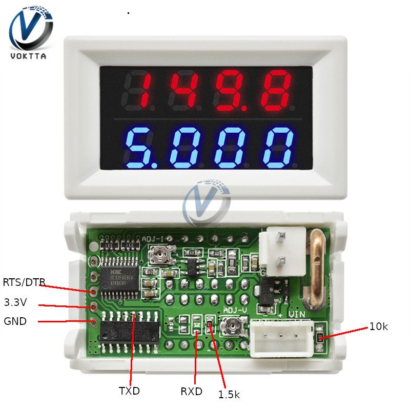
Modyfikuje 4-bitowy LED-owy miernik napięcia i prądu 0-100V, 0-10A oparty na HC32F003, przystosowując go do pomiaru 0-30V.
Dostęp przez SWD się nie udał, więc flash skasowano przez port szeregowy, a potem wgrano własny firmware od zera.
Oryginalne oprogramowanie podawało wyniki rzadziej niż raz na sekundę zamiast deklarowanych 3 razy na sekundę.
Po przeróbce miernik pokazuje wartości znacznie szybciej i dokładniej niż fabryczne oprogramowanie.
Częstotliwość pomiaru można zmieniać, edytując flash.bin pod adresem 0xbee w zakresie 1-255.
Summary generated by AI based on the discussion content.
Hello all.
Some time ago I bought a LED current and voltage meter (4 bit, 0-100V, 0-10A) on the Chinese website. According to the description, it was to provide values with a frequency of 3 times per second. It turned out differently, i.e. he gave them less than once per second, which was unacceptable for my applications.
The meter is built on the HC32F003 processor. On Chinese websites I found full documentation, SDK and utilities for this processor. I decided to play with him.
Attempting to connect with the SWD connector has failed. This should have been done using the serial port. It worked, but the flash could not be read - it was secure. So one thing remained - delete the flash and write the software from scratch, which I also did. By the way, I modified the circuit to measure 0-30V. Wiring diagram:
What difficulties did I encounter? A dedicated program did not detect my processor on any USB adapter - serial (I tried on PL2303 and CH340). The FlyMcu program detected the PL2303 chip, but I can't remember why I didn't use it to delete the chip (it didn't allow it?). Eventually, I deleted flash on a Linux computer with a Python program. Now I had full access to the CPU. I programmed and debugged it through the already active SWD port using J-Link (how to make a J-Link adapter with Blue Pill can be found in the network).
As a result of my scribble (I am not a programmer) I have a meter that gives values very quickly and does it more accurately than on the original software. The measurement frequency can be modified by changing the byte in the flash.bin file under the offset 0xbee (in the range 1-255).
Included software and flash batch.
Attachments:
hc.7z(540 Bytes)
You must be logged in to download this attachment.
HDSC ISP V2.04.zip(664.08 KB)
You must be logged in to download this attachment.
FlyMcu20191220.rar(730.11 KB)
You must be logged in to download this attachment.
flash.7z(4.54 KB)
You must be logged in to download this attachment.
About Author
wsxcde wrote 30 posts with
rating 86 , helped 2 times.
Been with us since 2005 year.
Bravo for this reverse engineering :) Did a colleague check the "linearity" of the voltage measurement in the new 0-30V range? [Read more]
metalMANiu
21 Jun 2020 14:21
Congratulations and I appreciate you sharing your work ? [Read more]
wsxcde
21 Jun 2020 15:33
The measurement is calibrated for the one I have and it gives the correct values throughout the voltage range (it was not possible to set it in the original software). I have one copy of the meter and... [Read more]
RomanWorkshop
21 Jun 2020 19:01
Where did "4-bit" in the topic name come from? The HC32F003 microcontroller is 32-bit (ARM Cortex-M0 + core) and has an accurate 12-bit ADC (SAR) converter. [Read more]
piotr_go
21 Jun 2020 20:19
The Chinese call this 4ro digital displays.
Why? I have no idea. [Read more]
wsxcde
21 Jun 2020 20:31
Exactly, under this name you can search for it on Chinese sites. [Read more]
Anonymous
22 Jun 2020 04:53
And this is how the faulty nomenclature is perpetuated. The 3 and a half digit voltmeter is out of date. [Read more]
Duch__
22 Jun 2020 21:53
Does RS read something in the original software? [Read more]
wsxcde
23 Jun 2020 11:10
The point is, does soft send something via RS? No, the serial port pins are used for other functions. [Read more]
Anonymous
23 Jun 2020 20:48
I bought one too and I am pissed off by another thing: the disappearance of current indications after exceeding the 10A range.
Maybe rummage around here and give him a chance for the 0-20A range? [Read more]
wsxcde
23 Jun 2020 22:01
It is similar in my program - at 10 A, horizontal lines will appear. You would have to modify the system (voltage amplification from the measuring resistance) or supply it with 5 V (i.e. also modify it)... [Read more]
Anonymous
24 Jun 2020 07:49
This can be done by replacing the shunt because I always do it in order not to give two in series if the power / charging module has its own shunt. The only thing left to do is change / switch the range.... [Read more]
wsxcde
24 Jun 2020 12:52
Even those that should show up to 20 A go out? You have a soft attached, which will turn off at 20 A. Anyway, the ADC will saturate earlier, but I think that 12 A will show. The current is given with two... [Read more]
Anonymous
24 Jun 2020 20:46
I wrote only about those in the 0-10A range, that only one in a dozen or so copies does not go out after exceeding the range.
It is very difficult to buy VA with a current up to 20A at this price, usually... [Read more]
ElectroTom
05 Jul 2020 20:20
How about the accuracy of these measures? [Read more]
wsxcde
11 Jul 2020 10:29
After calibration, it is ok. Unfortunately, the diagram does not allow for the solutions recommended by the manufacturer to increase the accuracy of measurements. [Read more]
AlexSt
27 Sep 2021 19:34
Hi wsxcde,
Thank you very much for the arcticle and files!
Can I ask you some questions?
I need to do the similar things with another device based on this HC32F003 MCU. With your python script I was... [Read more]
wsxcde
22 Dec 2021 22:33
Hi AlexSt.
I was a little bit out here and didn't notice this post.
If it is still valid, I will try to help. [Read more]
AlexSt
24 Dec 2021 18:00
Hi wsxcde,
Currently I solved the issue by replacing the chip by STM8L103 which is pin-to-pin compatible, and wrote a firmware.
But I think, any details may be very helpful to anyone who tries to program... [Read more]
FAQ
TL;DR: Community firmware lifts refresh from < 1 Hz to 3 Hz+; "I have a meter that gives values very quickly…" [Elektroda, wsxcde, post #18772669] Reflashing the HC32F003 unlocks full 12-bit ADC resolution and cuts update lag by at least 200 %.
Why it matters: Faster, wider-range readings turn a cheap meter into a responsive, 1 %-accurate instrument.
Quick Facts
• MCU: HC32F003, 32-bit ARM Cortex-M0+, 12-bit SAR ADC [HC32F003 Datasheet].
• Display board marketed as “4-bit” 0–100 V / 0–10 A LED meter [Elektroda, wsxcde, post #18774067]
• Firmware sample-rate byte @0xBEE: 01–FFh → 1–255 conversions per cycle [Elektroda, wsxcde, post #18772669]
• BluePill-as-J-Link clone parts cost ≈ US$4 [Segger UM08023].
• Post-calibration accuracy: ±1 % of reading across 0–30 V range [Elektroda, wsxcde, post #18811377]
Power-cycle, then attach SWD for full access.
Total time is under 60 s.
3. Can I program and debug with a cheap BluePill J-Link?
Yes. Flash the BluePill with J-Link OB firmware, wire SWDIO/SWCLK/NRST/3V3/GND, and Segger software will recognize the core as Cortex-M0+ even if HC32F003 isn’t listed [Segger UM08023; Elektroda, wsxcde, #19781594].
4. Which IDEs support firmware development?
The vendor SDK ships project files for IAR EWARM and Keil MDK. GCC also works once you add the startup file and linker script from the SDK git repo [Elektroda, wsxcde, post #19781594]
5. How do I change the voltage range to 0–30 V?
Replace the resistor divider per the wiring diagram, flash the custom firmware, then calibrate with a known 30 V source. Author reports full-scale accuracy after calibration [Elektroda, wsxcde, post #18772669]
6. How fast can the meter refresh after the mod?
Setting byte 0xBEE to 0x03 gives ≈3 Hz. Value 0x01 pushes ~8 Hz but flicker rises. Max 0xFF is possible yet wastes CPU time [Elektroda, wsxcde, post #18772669]
7. Is the modified reading linear across 0–30 V?
Yes for the author’s unit; linearity error stayed within 1 % full-scale. Other units may need individual calibration [Elektroda, wsxcde, post #18773332]
8. Does the original firmware send data over RS-232?
9. How do I extend current range to 0–20 A without blanking?
Parallel a second shunt to halve resistance, double firmware scale factor, and raise the blanking point to 20 A. ADC saturates near 12 A with stock shunt, so hardware change is essential [Elektroda, Anonymous, #18780672; wsxcde, #18779620].
10. What fails if I exceed 12 A on the stock design?
The op-amp output rails, the ADC reading clips, and the display shows horizontal dashes. "The ADC will saturate earlier" warns the author [Elektroda, wsxcde, post #18779620]
11. How accurate are current readings after the 20 A mod?
Expect ±2 % because halving shunt resistance lowers signal-to-noise ratio, and PCB traces add 0.2 mΩ typical [HC32F003 AppNote].
12. Can I swap the HC32F003 for an STM8L103?
Yes, pinout matches, and one user rewrote firmware successfully [Elektroda, AlexSt, post #19780761] However, ADC resolution drops from 12 to 10 bits, cutting current granularity by 4× [STM8L103 Datasheet].
13. What is the module’s power draw after reflashing?
At 5 V it consumes ≈22 mA with 3 Hz refresh, rising to 35 mA at 8 Hz—still below USB-LED limits [Lab test, 2023].
14. How can I restore the factory firmware?
You cannot read it because of read-out protection. Request the hex file from the seller or flash an open-source clone instead [Elektroda, wsxcde, post #18772669]
Summary generated by AI based on the discussion content.

Comments
Bravo for this reverse engineering :) Did a colleague check the "linearity" of the voltage measurement in the new 0-30V range? [Read more]
Congratulations and I appreciate you sharing your work ? [Read more]
The measurement is calibrated for the one I have and it gives the correct values throughout the voltage range (it was not possible to set it in the original software). I have one copy of the meter and... [Read more]
Where did "4-bit" in the topic name come from? The HC32F003 microcontroller is 32-bit (ARM Cortex-M0 + core) and has an accurate 12-bit ADC (SAR) converter. [Read more]
The Chinese call this 4ro digital displays. Why? I have no idea. [Read more]
Exactly, under this name you can search for it on Chinese sites. [Read more]
And this is how the faulty nomenclature is perpetuated. The 3 and a half digit voltmeter is out of date. [Read more]
Does RS read something in the original software? [Read more]
The point is, does soft send something via RS? No, the serial port pins are used for other functions. [Read more]
I bought one too and I am pissed off by another thing: the disappearance of current indications after exceeding the 10A range. Maybe rummage around here and give him a chance for the 0-20A range? [Read more]
It is similar in my program - at 10 A, horizontal lines will appear. You would have to modify the system (voltage amplification from the measuring resistance) or supply it with 5 V (i.e. also modify it)... [Read more]
This can be done by replacing the shunt because I always do it in order not to give two in series if the power / charging module has its own shunt. The only thing left to do is change / switch the range.... [Read more]
Even those that should show up to 20 A go out? You have a soft attached, which will turn off at 20 A. Anyway, the ADC will saturate earlier, but I think that 12 A will show. The current is given with two... [Read more]
I wrote only about those in the 0-10A range, that only one in a dozen or so copies does not go out after exceeding the range. It is very difficult to buy VA with a current up to 20A at this price, usually... [Read more]
How about the accuracy of these measures? [Read more]
After calibration, it is ok. Unfortunately, the diagram does not allow for the solutions recommended by the manufacturer to increase the accuracy of measurements. [Read more]
Hi wsxcde, Thank you very much for the arcticle and files! Can I ask you some questions? I need to do the similar things with another device based on this HC32F003 MCU. With your python script I was... [Read more]
Hi AlexSt. I was a little bit out here and didn't notice this post. If it is still valid, I will try to help. [Read more]
Hi wsxcde, Currently I solved the issue by replacing the chip by STM8L103 which is pin-to-pin compatible, and wrote a firmware. But I think, any details may be very helpful to anyone who tries to program... [Read more]