3W bicycle lamp [MAX16832] - power supply up to 60V
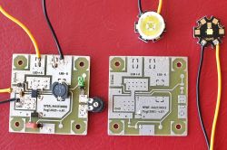
This mini-project is related to the previous one:
https://www.elektroda.pl/rtvforum/topic3790044.html
This time I took a Maxim MAX16832 (V MAX = 65V) supplying the diode with a constant current up to 1000 mA. This chip is manufactured in a hobbyist-friendly SOIC-08 housing with an added thermal pad underneath, which allows it to better radiate heat to the surface of the heat sink. This chip, like the MAX16822, is nice to fit. Note: the photos and diagram show the twin 1W version, please read the description carefully.
Today I present another version of this lamp (intended for city asphalts and bicycle paths) adapted to be powered by a battery with a constant voltage in the range of 7-65 V. Additionally, it can "feed" more than one Power LED (3W), so far I tested the operation of one Cree LED. The scheme is the same, a few elements have been changed, the PCBs are identical. Changes compared to the MAX16822 version:
1.Schottky diode 2A / 100V,
2.higher current choke (pay attention to the frequency of the inverter) - Coilcraft MSS1260-224KLB,
3.resistor programming the current R1 = 0R23 (theoretically it should give 867mA current for the Cree diode),
4. resistor R3 = 30k - at 20k the Cree diode receives too little current and does not behave stably.
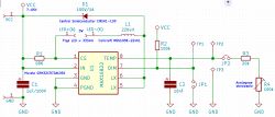
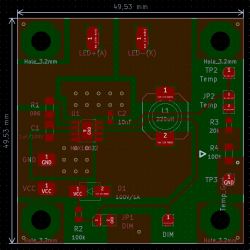
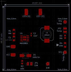
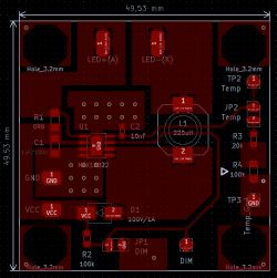
As you can see, the whole thing looks the same (except for a slightly larger choke, which, however, fits easily in its soldering field. It is worth recalling the numerous vias in the area of the integrated circuit, they were not put on display, they should be physically made, thanks to which we increase the cooling surface of the MAX16832 several times. .
Now measurements for one Cree 3W diode. Supply voltage 19.47V.
In the sleep mode (red jumper on), the voltage on the diode is 0V, current is 0mA, and the current consumed by the module is 0.61mA.
In the darker mode (green jumper on, minimal light - no worries, there is enough of it on the bicycle path), the voltage at Cree = 2.65V, the diode current is 75-> 65mA, the current consumed by the module is 13mA.
In bright mode (max), the voltage across the Cree is 3V, the current is 990-> 960mA, and the current consumed by the module is 263mA.
Marking 990-> 960mA means that at the beginning we have a current of 990mA, after a longer moment it drops to the level of 960mA.
Of course, in this version you should take care of the heat sink for the Cree diode, the module itself is very warm (especially the choke), but the integrated circuit has thermal protection (at 165 ° C), which gives hope that such a system will be sufficiently durable. I tested the module for several hours at home, it should be better cooled while driving.
Ultimately, I plan to install two series-connected Cree 3W LEDs with optics as in the description of the previous system, which will give better illumination of the road and shoulders and protect people from the opposite direction from glare.
In both versions(1W and 3W), in place of the potentiometer, you can solder a jumper (from R3 directly to the ground that we have on the Bottom side), the potentiometers are only used to adjust the desired brightness level of the dark mode, then you just need to solder the appropriate resistor R3.
If I had to use several Cree LEDs in series, more power would be released at this current. The choke heats up the most on the PCB. In this case, you can consider soldering copper radiation plates, but be careful that they do not come into contact with other "signals", they are not mass fields.
Summarizing these two projects, I plan to use the 3W module to build the front lamp. Simple logical switching on and switching the brightness gives good functionality of the lamp. The 1W module is very good for the tail light, it will normally work in darker mode, and when braking, it will turn on the bright mode as a brake light. A suitable contactor in the brake handle or the brake itself is sufficient.


Comments
@ yogi009 It's nice that you act ;) Do you have a ready version with a housing? Greetings [Read more]
Hi Sławek. Only these two PCB modules were fired. Housing - you know - the most difficult part for electronics. The more so because two features must be combined here: adequate cooling and sealing. You... [Read more]
Hello I personally use the PAM2863 chip. The voltage is lower, it is compensated by the current up to 2A and the simple construction of the system. PS I am wondering about the R2 resistor on the Dim... [Read more]
Is it good, I don't know. Certainly recommended by Maxim :-) In my two projects, the assumption was the flexibility of the supply voltage, so that the system works on both Li-Ion batteries and electric... [Read more]
Hello Does powering the LED diode directly through the L1 choke (no capacitive filtration) shorten the life of this diode? Ps. By what method did a colleague make the PCB? Was it a plotter? [Read more]
No, it doesn't. Many converters have exactly this way of powering the Power LED. This is a classic thermal transfer, and it is moderately successful. I tinned the whole thing so that I would not... [Read more]
I do not see such a solution in the documentation, even in the example PCB. Additionally, the condition in the description indicates low voltage. It would be enough to give a diode to be sure. Going... [Read more]
What did your colleague want to see? Anyone who wants to thoroughly analyze this particular chip should read the second catalog note regarding the finished module dedicated to this scalak. This is called... [Read more]
As for the processor, with the current it consumes, there is a lot to choose from dc / dc converters or other cheaper solutions. It's easier to seal one key than a potentiometer. As for the led,... [Read more]
Dude, if you read the topic from the beginning with understanding, you would know that the potentiometer is used here on the implementation module to set the brightness of the dark mode that interests... [Read more]
Generally, these are converters of lower power. More than once, I have encountered a case in which the failure of the filtering capacitor translated into the failure of the LED itself over time. Time... [Read more]
Exactly. This application is not accidental. [Read more]