Elektroda.com
Elektroda.com
X

3W bicycle lamp [MAX16832] - power supply up to 60V

yogi009 7377 12
This content has been translated flag-pl » flag-en View the original version here.
  • 3W bicycle lamp [MAX16832] - power supply up to 60V

    This mini-project is related to the previous one:
    https://www.elektroda.pl/rtvforum/topic3790044.html

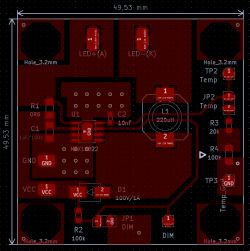
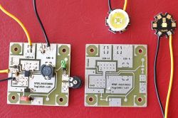
    This time I took a Maxim MAX16832 (V MAX = 65V) supplying the diode with a constant current up to 1000 mA. This chip is manufactured in a hobbyist-friendly SOIC-08 housing with an added thermal pad underneath, which allows it to better radiate heat to the surface of the heat sink. This chip, like the MAX16822, is nice to fit. Note: the photos and diagram show the twin 1W version, please read the description carefully.

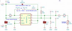
    Today I present another version of this lamp (intended for city asphalts and bicycle paths) adapted to be powered by a battery with a constant voltage in the range of 7-65 V. Additionally, it can "feed" more than one Power LED (3W), so far I tested the operation of one Cree LED. The scheme is the same, a few elements have been changed, the PCBs are identical. Changes compared to the MAX16822 version:

    1.Schottky diode 2A / 100V,
    2.higher current choke (pay attention to the frequency of the inverter) - Coilcraft MSS1260-224KLB,
    3.resistor programming the current R1 = 0R23 (theoretically it should give 867mA current for the Cree diode),
    4. resistor R3 = 30k - at 20k the Cree diode receives too little current and does not behave stably.
    3W bicycle lamp [MAX16832] - power supply up to 60V 3W bicycle lamp [MAX16832] - power supply up to 60V 3W bicycle lamp [MAX16832] - power supply up to 60V 3W bicycle lamp [MAX16832] - power supply up to 60V

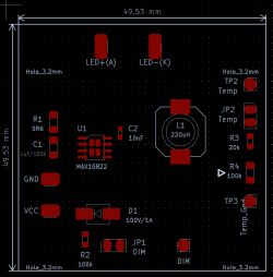
    As you can see, the whole thing looks the same (except for a slightly larger choke, which, however, fits easily in its soldering field. It is worth recalling the numerous vias in the area of the integrated circuit, they were not put on display, they should be physically made, thanks to which we increase the cooling surface of the MAX16832 several times. .

    Now measurements for one Cree 3W diode. Supply voltage 19.47V.

    In the sleep mode (red jumper on), the voltage on the diode is 0V, current is 0mA, and the current consumed by the module is 0.61mA.
    In the darker mode (green jumper on, minimal light - no worries, there is enough of it on the bicycle path), the voltage at Cree = 2.65V, the diode current is 75-> 65mA, the current consumed by the module is 13mA.
    In bright mode (max), the voltage across the Cree is 3V, the current is 990-> 960mA, and the current consumed by the module is 263mA.

    Marking 990-> 960mA means that at the beginning we have a current of 990mA, after a longer moment it drops to the level of 960mA.

    Of course, in this version you should take care of the heat sink for the Cree diode, the module itself is very warm (especially the choke), but the integrated circuit has thermal protection (at 165 ° C), which gives hope that such a system will be sufficiently durable. I tested the module for several hours at home, it should be better cooled while driving.

    Ultimately, I plan to install two series-connected Cree 3W LEDs with optics as in the description of the previous system, which will give better illumination of the road and shoulders and protect people from the opposite direction from glare.

    In both versions(1W and 3W), in place of the potentiometer, you can solder a jumper (from R3 directly to the ground that we have on the Bottom side), the potentiometers are only used to adjust the desired brightness level of the dark mode, then you just need to solder the appropriate resistor R3.

    If I had to use several Cree LEDs in series, more power would be released at this current. The choke heats up the most on the PCB. In this case, you can consider soldering copper radiation plates, but be careful that they do not come into contact with other "signals", they are not mass fields.

    Summarizing these two projects, I plan to use the 3W module to build the front lamp. Simple logical switching on and switching the brightness gives good functionality of the lamp. The 1W module is very good for the tail light, it will normally work in darker mode, and when braking, it will turn on the bright mode as a brake light. A suitable contactor in the brake handle or the brake itself is sufficient.

    Cool? Ranking DIY
    About Author
    yogi009
    Level 43  
    Offline 
    yogi009 wrote 13572 posts with rating 2329, helped 808 times. Been with us since 2006 year.
  • #2
    Slawek K.
    Level 35  
    @ yogi009 It's nice that you act ;)
    Do you have a ready version with a housing?

    Greetings
  • #3
    yogi009
    Level 43  
    Hi Sławek. Only these two PCB modules were fired. Housing - you know - the most difficult part for electronics. The more so because two features must be combined here: adequate cooling and sealing. You know, you drive in different conditions. Besides, some shockproof handle will have to be made so that the optics keeps the line of light (of course, I assume bicycle paths and asphalt). When I make a target heat sink for two (or maybe three) Cree diodes, I will provide extended measurement results, this time from a power supply of approx. 50VDC. I am pleased with the fact of using really bright (for this current) Cree diodes, additionally with a high real color rendering index and components recommended by Maxim (e.g. specific choke models). The brightness of each of the Cree diodes according to their catalog note for such a current is 450 lm, i.e. with two diodes we have 900 lm, and with three diodes - 1,350 lm in front of the optics dedicated to these diodes (Cree XP-G3). Well, you can see something in the night city. Such a construction will probably not work during night descents along forest paths, but here we are fighting for light for a civilian trekking bike :-)
  • #4
    nouki
    Level 25  
    Hello

    I personally use the PAM2863 chip. The voltage is lower, it is compensated by the current up to 2A and the simple construction of the system.

    PS I am wondering about the R2 resistor on the Dim leg - is it a good solution?

    3W bicycle lamp [MAX16832] - power supply up to 60V
  • #5
    yogi009
    Level 43  
    nouki wrote:
    PS I am wondering about the R2 resistor on the Dim leg - is it a good solution?

    Is it good, I don't know. Certainly recommended by Maxim :-) In my two projects, the assumption was the flexibility of the supply voltage, so that the system works on both Li-Ion batteries and electric bike batteries, i.e. in practice 36 and 48V packages with a maximum voltage in a charged state of 54V. The module will withstand a maximum of 65V at the input, so 60V batteries could enter this range, but ... While the 16S x nominal 3.7V package gives slightly below 60V, right after charging we have 67.2V (16S x 4.2V) . So this setup is out.
  • #6
    Anonymous
    Level 1  
  • #7
    yogi009
    Level 43  
    spec220 wrote:
    Does powering the LED diode directly through the L1 choke (no capacitive filtration) shorten the life of this diode?

    No, it doesn't. Many converters have exactly this way of powering the Power LED.

    spec220 wrote:
    By what method did a colleague make the PCB? Was it a plotter?

    This is a classic thermal transfer, and it is moderately successful. I tinned the whole thing so that I would not be chased by time, you know - prototyping likes to last, and bare copper without varnish Positiv quickly loses its shine (just like naked ... ah, never mind ;-) ). If it were a checked board, designed for quick assembly, I would solder without tinning and then varnished it after a quick test.
  • #8
    nouki
    Level 25  
    yogi009 wrote:
    nouki wrote:
    PS I am wondering about the R2 resistor on the Dim leg - is it a good solution?

    Is it good, I don't know. Certainly recommended by Maxim :-)

    I do not see such a solution in the documentation, even in the example PCB.
    Additionally, the condition in the description indicates low voltage. It would be enough to give a diode to be sure.
    Going through the documentation
    IN, CS, LX, DIM to GND ......................................... -0.3V to + 70V
    So without a resistor it will also be ok :)
    I do not see the efficiency of the system either - it is known that the quality and type of elements have an influence, but they could have given theirs.

    When it comes to power, maybe the colleague's universality wins.
    I personally have 2x cob with a current of 350mA and about 1000 lm to ride in the field. The panel itself is 140x15 two pieces. In addition, I have the option of turning on one or two with brightness adjustment every 20%. Power supply 5x li-po. Run time 4 hours
    Cree has a small footprint and high power, which causes a problem with cooling.
    If a colleague would like to have universality, as he writes, it would be useful to change the lens.
    The terrain is rather punctual and the scattered city will irritate others.

    Of course that's my opinion :)
    greetings
  • #9
    yogi009
    Level 43  
    nouki wrote:
    I do not see such a solution in the documentation, even in the example PCB.

    What did your colleague want to see? Anyone who wants to thoroughly analyze this particular chip should read the second catalog note regarding the finished module dedicated to this scalak. This is called putty. And there, the manufacturer of the system recommends exactly this diagram and practically this layout. Of course, you can discuss with the manufacturer :-) The efficiency of the module is also given.

    As for the Cree, the inquisitive could read that it is about the XP-G3, which can be powered by 2A, then it is really warm. Here we have half of this current, a relatively small heat sink and dedicated MBPCB are more than enough. I don't want to discuss the viability of the Cree compared to Chinese inventions, nor the CRI. Here's a promise from Cree:

    https://www.maritex.com.pl/product/attachment/89128/945916614ea3187b8c7e1480de5bfb1e

    Show me a note of these eastern inventions. Flickering? How much is alive? What is the real efficiency (I do not mean printing the text "10000 mAh" on a Li-Ion 16850 cell)? In addition, this system has analog control, which eliminates the need to add a module that produces the PWM waveform. Such a module is usually a microcontroller, which requires a stabilized 3 / 5V power supply. So some working 7-65VDC power supply for 3 / 5VDC. All this causes the expansion of the system. I know that the Far Eastern tiger is not afraid of anything, but personally, I prefer book applications in which what you program with a calculator in your hand you get in practice.

    I agree with one, in the target PCB for peace of mind you can give the so-called power input. diode of life, the voltage drop caused by one semiconductor junction is negligible here. Instead, we throw out the potentiometer and arrange the two switches a bit more ergonomically. But these are little things.
  • #10
    nouki
    Level 25  
    As for the processor, with the current it consumes, there is a lot to choose from dc / dc converters or other cheaper solutions.
    It's easier to seal one key than a potentiometer.
    As for the led, I have them for 1.5 years and who said that my friends Cree is not Chinese crap :)
    As for the sense of the chip on dim, please measure the voltage and think what can happen by connecting a 3.3V processor there.
    Li-po from the laptop and I made the lamp myself. I think it is easy to calculate the capacity, since at 700mA it works for 4 hours.

    greetings

    PS

    Anyone who wants to thoroughly analyze this particular chip should read the second catalog note regarding the finished module dedicated to this scalak.

    4. resistor R3 = 30k - at 20k the Cree diode receives too little current and does not behave stably.
    This producer did not know?
  • #11
    yogi009
    Level 43  
    Dude, if you read the topic from the beginning with understanding, you would know that the potentiometer is used here on the implementation module to set the brightness of the dark mode that interests us. This element is not present on the target board. In addition to the sealing in vehicles, we have numerous vibrations, moisture and dust, which are not loved by the potentiometer sliders.

    Second: there may be cheaper and better solutions. If you know them, you can post your article here, preferably in the DIY section, ideally something made with your own hands.

    Thirdly: I accept the possibility of producing Cree in the Far East, but ... they also make half of the good cars there, branded drives for Dutch and German e-bikes (I saw Chinese "Made in China" signatures inside the Gazelle engine for around 1500- 2000 Euro). I also saw the same inscription on the inner tube of the front fork of such a bicycle. What is the conclusion? A few things. Large producers have lowered production costs and raised product prices. Logic :-) For a gangster. Besides, these large, well-known companies watch over the quality of production, maybe not like they used to in Sweden, but certainly better than the Chinese no-name counterfeit factory.

    Fourth, read about this DIM entry and then write an elaboration.

    Fifthly, why another converter, if here we can have functionality without it and without a microcontroller (and therefore without the need to write code, which is a problem for many)?

    In general, respect my time and read the sources carefully first, then possibly show some constructive variants, or prove a connection error. I think engineers at Maxim will be happy to read.


    nouki wrote:
    This producer did not know?

    Yes, it's logical, he didn't know :-) Therefore, he added measurement fields to study the behavior of the system in order to determine the optimal point.
  • #12
    Anonymous
    Level 1  
  • #13
    yogi009
    Level 43  
    spec220 wrote:
    More than once I have encountered a case where the failure of the filtering capacitor over time translated into the failure of the LED itself

    Exactly. This application is not accidental.