logo elektroda
logo elektroda
X
logo elektroda

1W bicycle lamp [MAX16822] - power supply up to 60V

yogi009 9120 10
ADVERTISEMENT
Treść została przetłumaczona polish » english Zobacz oryginalną wersję tematu
  • Two-layer PCB for a bicycle light with electronic components.

    Some time ago I made a bicycle lamp powered by a bicycle hub dynamo. As such a dynamo in an unloaded state can generate definitely high voltages (up to 100V according to a German source), I was looking for a converter that can withstand high voltages. The choice fell on the chip from Maxim MAX16822 (V MAX = 65V) supplying the diode with a constant current up to 350 mA. This chip is manufactured in a hobbyist-friendly SOIC-08 housing without a thermal pad underneath, in a word, it is nice to install.

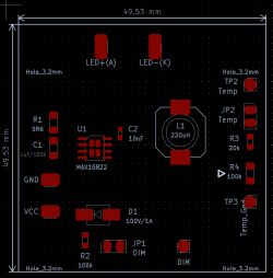
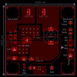
    Today I present a new version of this lamp (intended for city asphalts and bicycle paths) adapted to be powered by a battery with a constant voltage in the range of 7-65V. Additionally, it can power more than one Power LED (1W), I tested 1-3 such LEDs. Maybe the schematic and PCB first:
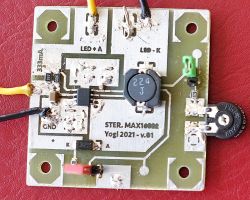
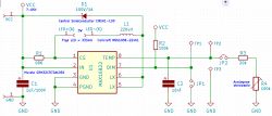
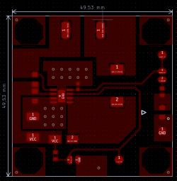
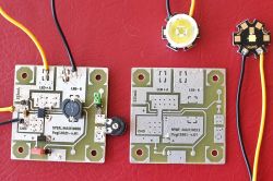
    View of the PCB with the control circuit for a dynamo-powered bike light. Electrical schematic of bicycle lamp with MAX16822 circuit. PCB schematic for a bicycle light using the MAX16822 circuit Schematic and PCB design for a two-layer circuit board for a bicycle light based on the MAX16822 chip. Two-layer PCB for a bicycle lamp with MAX16822 circuit. Two-layer PCB measuring 49.53 mm with visible traces, GND, VCC connections, and components.

    PCB is double-layer, the Bottom layer is a spilled mass that also acts as a heat sink. The emitted amount of heat is not frighteningly large, but with 2-3 LEDs it can heat up the circuit well without proper heat dissipation on the PCB. According to the manufacturer, at 165 ° C there is a sudden current limitation (thermal protection). I have never seen such a mode in practice.

    The system is interesting because in addition to determining the maximum current supplied to the diode (according to the note 0R6 it gives a diode current of 333 mA, in my example I used a 0R64 resistor which theoretically gave a diode current of 310 mA), you can control the brightness using the PWM input (standard in these applications). However, in the case of a higher supply voltage (eg 60V) it is difficult to find a small stabilizer to power the microcontroller (eg Attiny13) generating the PWM signal. And here it turned out that a trick can be used to analogously limit the diode current. It is enough to connect the temperature control input to ground through a resistor, which will reduce the diode current (external thermal protection). The diagram shows a 20 k? resistor and a 100 k? potentiometer, thanks to which we can adjust the brightness of the LED diode in a fairly wide range. During the tests, I came to the conclusion that this 20 k? resistor is enough, and the outputs for the 100 k? potentiometer / resistor can be shorted - we will then get the reduced diode brightness mode. Removal of the green jumper returns the LED to full brightness mode. On the other hand, giving the low state to the PWM input causes the LED to go out (let's call it the "Sleep" mode), then the current consumption is around 1 mA.

    What does it all mean? First of all, we have a simple circuit that can power 1, 2, 3 and maybe more Power LEDs (study the datasheet). Second, the logic switch is a simple jumper (or a small contact switch). Third, we can just as easily set two levels of brightness, e.g.. light for the bike path and light for slightly darker corners. We might as well imagine a red rear light with a brake light option - just install the microswitch in the brake levers or on the brakes themselves. There is no need to use an additional PWM system, although it can of course be done (and obtain e.g. orange hazard lights).

    Now for some quick measurements.

    1. 50V power supply, 1 LED 1W - 145 lm.

    AT LED = 2.78 V (U LED LOW = 2.57 V) - voltage across the LED
    AND LED = 317.3 mA (I. LED LOW = 17.12 mA) - LED currents
    AND INPUT = 26.58 mA (I INPUT LOW = 3.25 mA) - current drawn from the battery
    AND SLEEP = 0.81 mA (I SLEEP LOW = 1.03 mA) - current consumption in "Sleep" mode

    2. 50V power supply, 2 LEDs 1W in series - 290 lm.

    AT LED = 5.51 V (U LED LOW = 5.13V)
    AND LED = 318 mA (I LED LOW = 16.6 mA)
    AND INPUT = 45.2 mA (I INPUT LOW = 5 mA)
    AND SLEEP = 0.81 mA (I SLEEP LOW = 1.03 mA)

    3. 50V power supply, 3 LEDs 1W in series - 430 lm.

    AT LED = 8.27 V (U LED LOW = 7.70 V)
    AND LED = 319.6 mA (I. LED LOW = 15.54 mA)
    AND INPUT = 63.8 mA (I INPUT LOW = 6.64 mA)
    AND SLEEP = 0.81 mA (I SLEEP LOW = 1.03 mA)

    The "LOW" mode is simply a green jumper closed. The "SLEEP" mode is a closed red jumper (low state on PWM input). As you can see, the power consumption is perfectly acceptable. The system is suitable, among others for use on e-bikes up to 60V, I tested it successfully with 54V.

    Soon I will add measurements for lower supply voltages.

    It is worth using interesting Power LED diodes (eg Cree XP-G3 with a brightness of 164 lm / 350 mA) with directional optics so as not to dazzle cyclists and walkers approaching from the opposite direction (round optics 7 ° plus the second elliptical ? 7 °). The effect is really good. Nevertheless, I am already announcing a slightly more powerful, three-diode version of the lamp (current approx. 870 mA - over 1200 lm), I plan to build and test such a module in the near future.

    Cool? Ranking DIY
    About Author
    yogi009
    Level 43  
    Offline 
    yogi009 wrote 14563 posts with rating 2595, helped 843 times. Been with us since 2006 year.
  • ADVERTISEMENT
  • #2 19335494
    Maciek_C
    Level 14  
    Hello
    A very nice thing, unfortunately there are not many good, "non-blinking" lamps at an affordable price on the market, using such a dynamo, so your lamp is an interesting project all the more.

    Do you already have a housing for this?

    I also used to do a lot of good lighting based on the hub dynamo (original Axa companies pulsed terribly) and finally went the easy way - I made a DC installation on the bike, rectifying the output voltage of the generator and filtering with 20,000uF / 35V capacitors.
    I hid the capacitors and the bridge in the steerer tube.

    As a front lamp, I have successfully used such a cheap invention (with an integrated converter) - a 12V 9W work lamp for the price of PLN 30:

    1W bicycle lamp [MAX16822] - power supply up to 60V

    I know, maybe it's a light guerrilla fighter, but it has already traveled about 10,000 km and it serves well.
    After some time, following the blow, I added a motorcycle phone holder to the bike, which allows you to charge the phone from a dynamo (for a trifle PLN 60):

    1W bicycle lamp [MAX16822] - power supply up to 60V

    In addition, the rear light is made on the MC34063 and the whole thing works great.
  • ADVERTISEMENT
  • #3 19335546
    yogi009
    Level 43  
    First, I will test a two or three times more powerful converter, then I will make a housing. With currents of 330-700 mA (750 mA this will be the next prototype), it is difficult to expect a great effect when driving at night on forest paths. However, in the city and on asphalt, for example, 3 such LEDs in the front should do the job (3 x 3W) - the cited Cree LEDs then give about 980 lumens. It is still not the Chinese 80,000 lumens, because it is also not a converter for higher currents. One Cree XP-G3 diode will take up to 2A of current, which gives an estimated 930 lumens, with three such LEDs we have about 2800 lumens of brightness. Additionally, this series in the "White" light version has a CRI of 90%.

    And this 1-watt converter is very suitable for city paths and asphalts - it is impossible not to see it. You can also make a very bright tail light. For sure the safety level will increase many times, the brightness of such a red LED with a power of 1W is equal to the brightness of mopeds, it is enough to choose the right optics with a slightly wider scattering.

    I know that you can buy everything from a Chinese and usually cheap. But I don't know if it is good. Besides, I prefer (and like) to do something for myself.
  • ADVERTISEMENT
  • #4 19335573
    conisl
    Level 11  
    yogi009 wrote:
    With currents of 330-700 mA (750 mA this will be the next prototype), it is difficult to expect a great effect when driving at night on forest paths.


    I don't think it is possible to make a dynamo-powered lamp that would be fine in a night forest. I have seen strong bicycle lamps once, but they are powered by a battery attached to the frame. However, even with them, I wouldn't risk driving outside the city, you can hurt yourself.

    Regards
  • #5 19335579
    yogi009
    Level 43  
    conisl wrote:
    I don't think it is possible to make a dynamo-powered lamp that would be fine in a night forest.


    Buddy, read it with understanding. This is not a dynamo powered lamp. I described that one a long time ago, enter "MAX16822" in the forum search engine, you will find the old article.
  • #6 19335602
    conisl
    Level 11  
    yogi009 wrote:
    Buddy, read it with understanding. This is not a dynamo powered lamp.


    Do not be angry, but the content of your article does not show how you power the improved version of the lamp.
  • #7 19335640
    Millaka
    Level 24  
    And wouldn't it be better to use the dynamo to charge the 18650 and then power the lamp from there?
    Then, for sure, nothing would blink and you could shine even when stationary.
  • #8 19335693
    @GUTEK@
    Level 31  
    Dynamo has too little current to charge 18650, at least that's my opinion.

    As for the dynamo lamp, you can buy the XC-997C for less than PLN 30 - there are several versions of these lamps, the C version is powered by a dynamo. It is not a miracle, but it has a 1F capacitor inside (if I remember correctly). Thanks to that, it does not blink and it still shines a moment after stopping.
    There is even a video of how it shines - https://www.youtube.com/watch?v=bgCicw9sBFo
  • ADVERTISEMENT
  • #9 19335724
    yogi009
    Level 43  
    conisl wrote:
    Do not be angry, but the content of your article does not show how you power the improved version of the lamp.

    Ok, I underlined this in the original article in bold. To all, this is the battery powered version . I am writing about it, among others indicating that it is suitable for most electric bikes that have 24, 36 or 48V batteries.

    Millaka wrote:
    And wouldn't it be better to use the dynamo to charge the 18650 and then power the lamp from there?
    Then, for sure, nothing would blink and you could shine even when stationary.

    I don't know where you're getting that blinking. You will not notice this effect in this construction.

    @GUTEK@ wrote:
    And as for the dynamo lamp, you can buy the XC-997C for less than PLN 30

    This is DIY, which is the section in which we present own designs . Auction portals and their offer are not an authority here.
  • #10 19360661
    Łukaszoo
    Level 16  
    I don't know about a hub dynamo, but a "regular" dynamo in a way behaves like a current source with an efficiency of around 500mA and a maximum voltage depending on how fast we are going.

    Based on this information, I assembled a lamp that had two 3W power LEDs (in series), and from the electronics only a rectifier bridge and a capacitor. It worked great, never failed, the dynamo never gave out a current that was dangerous for those LEDs. At the same time, the LEDs were lit when driving the bike (which is why I was tempted to 2 pcs in series, despite the higher voltage required). Therefore, it seems a bit overcomplicated to me.
    If it was a li-ion battery charger that uses dynamo energy - then it would make the most sense.
  • #11 19365071
    yogi009
    Level 43  
    And this LED is not blinking at low speed? A dedicated inverter, however, has several advantages, it monitors the programmed current, thanks to which it maintains the brightness level at a constant level. Anyway, this is a topic about power ... from batteries or accumulators :-) I wrote this in bold in the first post :-)

Topic summary

A user has developed a bicycle lamp powered by a battery with a constant voltage range of 7-65V, utilizing the MAX16822 chip from Maxim, which can handle up to 65V and supply a constant current of 350 mA. The lamp is designed for urban use and can power multiple 1W Power LEDs, with tests showing it can effectively illuminate city paths. Discussions include the challenges of using hub dynamos, the potential for using a battery to avoid flickering, and the advantages of dedicated inverters for maintaining brightness. Some users share their experiences with alternative lighting solutions and express skepticism about the effectiveness of dynamo-powered lamps in low-speed scenarios.
Summary generated by the language model.
ADVERTISEMENT