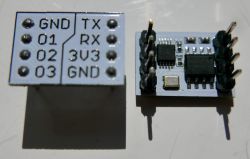
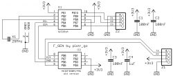
FAQ
TL;DR: Si5351A module delivers 4 kHz–112.5 MHz on three outputs [Elektroda, piotr_go, post #19559788]; "200 MHz works" [Elektroda, piotr_go, post #19560478], but only two outputs stay stable above 112.5 MHz. UART menu plus EEPROM lets you store presets in seconds. Calibration command ("c") corrects crystal error in <1 min [Elektroda, Menu Image, post #19559788]
Why it matters: A cheap UART-controlled clock can replace dozens of quartz crystals or VFO coils in hobby RF projects.
Quick Facts
• Frequency range: 4 kHz–112.5 MHz on 3 outputs; up to 200 MHz on 2 outputs [Elektroda, piotr_go, post #19560478]
• Frequency step: Typical 1 Hz with 25 MHz crystal [SiLabs AN619].
• Output swing: 3 Vpp @14 MHz, 0.45 Vpp @100 MHz [Elektroda, ArturAVS, post #19561255]
• Interface: 115 200 bps UART; commands F1–F3, c, w [Elektroda, piotr_go, post #19559788]
• Supply voltage: 3.3 V single rail [Elektroda, piotr_go, post #19559788]
What frequency coverage can I expect?
The menu supports 4 kHz–112.5 MHz on all three outputs [Elektroda, piotr_go, post #19559788] Two outputs keep working up to 200 MHz if you need higher range [Elektroda, piotr_go, post #19560478] External projects push identical chips to about 290 MHz, but signal purity degrades quickly [Elektroda, djbpm, post #19560451]
Why did the author cap the default range at 112.5 MHz?
He believed the fractional divider must stay ≥8, and he only needed ≤30 MHz for his own work [Elektroda, piotr_go, post #19559941] Above 112.5 MHz only two channels remain, so the simpler limit avoids user confusion.
Can the board really output 200 MHz?
Yes. Scope screenshots show 195–200 MHz tuning on two channels [Elektroda, piotr_go, post #19560478] Expect lower amplitude and higher phase noise than below 100 MHz.
How does amplitude change with frequency?
Measured swing drops from 3 Vpp at 14 MHz to 0.45 Vpp at 100 MHz, a-6.5 dB/octave trend [Elektroda, ArturAVS, post #19561255] Mismatched loads or 1:1 probes exaggerate the loss [Elektroda, H3nry, post #19563743]
What is the output impedance and how should I terminate it?
Si5351A drivers are low-Z CMOS, approximating 50 Ω. Terminate each line with 50 Ω to ground or use SMA/BNC connectors to avoid RLC resonances [Elektroda, lazor, post #19562274] “Mismatch hides the real waveform,” notes lazor [Elektroda, 19562007]
How do I calibrate the crystal?
- Connect a known-good frequency counter.
- Send the “c” command over UART; the MCU measures and computes ppm error [Elektroda, Menu Image, post #19559788]
- Press “w” to store the correction in EEPROM [Elektroda, piotr_go, post #19559788] Calibration takes under one minute.
Can I add CAT control or I²C port expanders?
The firmware is closed-source, but extra I²C devices and CAT framing could be added in a v2 release [Elektroda, piotr_go, post #19561702] A reference Arduino CAT driver for Si5351 exists in the RS-HFIQ transceiver project [ArturAVS link, #19560693].
Does the PCB follow RF design rules?
No. Traces are short but lack controlled impedance and SMA feeds. Re-route outputs as 50 Ω micro-strips and add ground stitching vias for cleaner edges [Elektroda, ArturAVS, post #19562061]
What edge-cases should I watch for?
Above 150 MHz harmonic energy rises, and some Si5351A samples fail beyond 290 MHz [Elektroda, djbpm, post #19560451] EEPROM burnout occurs after ~100 k write cycles, so avoid constant frequency sweeps [SiLabs datasheet].
Is the source code available?
Only binary HEX files are shared to prevent cloning, although a menu snippet was sent privately to one user [Elektroda, miszcz310 & piotr_go, #19579732-#19579754].
What instruments are required for accurate testing?
Use at least a 300 MHz-bandwidth oscilloscope with a 10:1 probe or a spectrum analyzer. A 1:1 probe skews readings above 50 MHz [Elektroda, lazor, post #19565749] 50 Ω termination is mandatory.
How much does the project cost to build?
Si5351A module ≈ €4, HK32F030 MCU ≈ €1, PCB and passives ≈ €3. Total parts under €10 excluding connectors (July 2025 retail, Mouser list).


Comments
Why did you cut the bandwidth so much? According to the manufacturer, it works from 2.5kHz to 200MHz, I managed to chase it to about 180MHz in Bascom, I didn't need more. [Read more]
Somewhere I read that the minimum divisor is 8 for some versions of Si5351. I don't think I would even have anything to check if it works at higher frequencies; besides - I don't need any more,... [Read more]
Si5351 is used in NanoVNA and reaches even 300MHz there, although with some copies there are problems above 290, but up to 290 is probably every piece. [Read more]
200MHz works, but at higher frequencies like 112.5MHz you can only use 2 channels. I will leave Soft as is for now. https://obrazki.elektroda.pl/1473496000_1628716132_thumb.jpg The screen shows... [Read more]
You see. This method of control will facilitate the work on SDR construction based on, for example, YU1LM. A suitable driver has been developed for the Si570 generator that enables CAT control from a PC.... [Read more]
As for me, it is not enough to say what the quality of this generator is. The equipment for verifying such equipment is not cheap, but such a frequency meter is ... well, definitely too low for you, Piotr. ... [Read more]
Heh, they couldn't call it worse. Take it here find it by typing "cat" in google. :D I found something: I do not have access to the appropriate equipment. If I don't buy something myself,... [Read more]
I just checked on my generator; @ 14MHz ~ 3Vpp for @ 100MHz ~ 450mV. Unfortunately, the soft for Arduino Nano from RS-HFIQ blocks the generator's output for frequencies outside the amateur bands. The... [Read more]
@arturavs SDR requires much better hardware. The mismatched path and lack of termination lead to the oscilloscope measurements to be incorrect (in the sense what you see on the oscilloscope is not the... [Read more]
Maybe in v2, if it does. It would be better to change the slinger to one that is more accessible. Today I found an old damaged kit for a 1.2Ghz meter from the lumber. It must have been lying for 20 years.... [Read more]
No offense to your knowledge, but it doesn't necessarily have to be better equipment (organoleptically tested). After all, Si5351 does not participate directly in the signal processing for SDR but... [Read more]
It depends on what modulation (FM, AM, QPSK, QAM?) And I don't mean directly about Si5351 but about PCB design. Because a good scalak is also followed by the need to know how to design a PCB for such... [Read more]
You're right here. Piotr made the board as he did, ignoring all the rules for RF, and at least it would fit to output the signals from Si to the SMA sockets through appropriately designed signal paths.... [Read more]
There is (photo from the menu) Exactly. This 112.5MHz is mainly a curiosity so that you can check on the radio if it works. [Read more]
In fact, it somehow escaped my attention :D [Read more]
It should only be noted that the generator output is low Z (50 ohms) and with impedance mismatch we have cases where RLC or RC filters are formed, so you have to assume that if something does not work,... [Read more]
I didn't connect it to the radio. I have attached a piece of wire and you can easily pick it up within a dozen or so meters. [Read more]
What do you receive? also a piece of wire? [Read more]
The yellow one in the film. Possibly an antenna that the radio has. A simple test. Everyone probably has an FM radio at home, phone or car. [Read more]