Elektroda.com
Elektroda.com
X

UART configurable frequency generator by piotr_go

piotr_go 7221 27
This content has been translated flag-pl » flag-en View the original version here.
  • UART configurable frequency generator by piotr_go

    Hello
    Sometimes a man needs some unusual generator or quartz. You have to wait 2 days or 2 months for an order, and I am too stingy to buy a proprietary generator, so what? You have to do something yourself.
    For a long time I had an idea ... Something small, I set the frequencies and I forget.
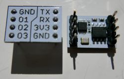
    So I present the generator module project based on the Si5351A chip and the HK32F030MJ4M6 microcontroller.
    The generator has 3 outputs with a frequency range of 4kHz ... 112.5MHz and is configurable via the UART interface and the settings are stored in the built-in EEPROM in HK32F030MJ4M6.
    Own Soft, written in C.
    Power supply 3.3V.


    Menu:
    UART configurable frequency generator by piotr_go
    'F1', 'F2', 'F3' - frequency configuration
    'c' - calibration
    'w' - save settings
    Baudrate: 115200

    Diagram:
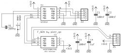
    UART configurable frequency generator by piotr_go
    When using the newer version HK32F030MJ4M6, the SDA / SCL pins must be switched.
    As there was little space on the board, I used a pull-up built into the microcontroller for the SDA ("kids, don't do it at home" :D ).
    SCL is push / pull controlled.
    Attachments:

    Cool? Ranking DIY
    About Author
    piotr_go
    DIY electronics designer
    Offline 
    piotr_go wrote 2562 posts with rating 2840, helped 88 times. Been with us since 2003 year.
  • #2
    ArturAVS
    Moderator HP/Truck/Electric
    Quote:
    The generator has 3 outputs with a frequency range of 4kHz ... 112.5MHz

    Why did you cut the bandwidth so much? According to the manufacturer, it works from 2.5kHz to 200MHz, I managed to chase it to about 180MHz in Bascom, I didn't need more.
  • #3
    piotr_go
    DIY electronics designer
    ArturAVS wrote:
    Why did you cut the bandwidth so much?

    Somewhere I read that the minimum divisor is 8 for some versions of Si5351.
    I don't think I would even have anything to check if it works at higher frequencies; besides - I don't need any more, 1 ... 30MHz is enough for me.
    Hmmmm, I can see SDRem, if it works, I will post a newer soft.
  • #4
    djbpm
    Level 23  
    Si5351 is used in NanoVNA and reaches even 300MHz there, although with some copies there are problems above 290, but up to 290 is probably every piece.
  • #5
    piotr_go
    DIY electronics designer
    200MHz works, but at higher frequencies like 112.5MHz you can only use 2 channels.
    I will leave Soft as is for now.
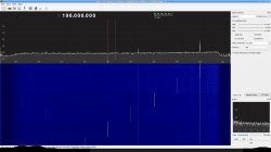
    UART configurable frequency generator by piotr_go
    The screen shows a change of 195 ... 200MHz.
  • #6
    ArturAVS
    Moderator HP/Truck/Electric
    You see. This method of control will facilitate the work on SDR construction based on, for example, YU1LM. A suitable driver has been developed for the Si570 generator that enables CAT control from a PC. There is also a version for Si5351, but this is mediated by Arduino Nano, because it also controls the switching of bandpass filters; https://sites.google.com/site/rshfiqtransceiver/ The schema and sources are available, then you could try to implement CAT in your software.
  • #7
    _lazor_
    Moderator of Designing
    piotr_go wrote:
    200MHz works, but at higher frequencies like 112.5MHz you can only use 2 channels.
    I will leave Soft as is for now.
    UART configurable frequency generator by piotr_go
    The screen shows a change of 195 ... 200MHz.


    As for me, it is not enough to say what the quality of this generator is. The equipment for verifying such equipment is not cheap, but such a frequency meter is ... well, definitely too low for you, Piotr.

    It would be useful to do a sweep and check how the signal amplitude changes and what is the SNR. And when measuring, it would be useful to terminate the circuit with 50 ohms.

    And what exactly does the output impedance look like? did you keep 50 ohms?
  • #8
    piotr_go
    DIY electronics designer
    ArturAVS wrote:
    you could try to implement CAT in your software

    Heh, they couldn't call it worse. Take it here find it by typing "cat" in google. :D
    I found something: FT-897D_Ya...mmands.pdf Download (121.01 kB)

    _lazor_ wrote:
    It would be useful to do a sweep and check how the signal amplitude changes and what is the SNR. And when measuring, it would be useful to terminate the circuit with 50 ohms.
    And what exactly does the output impedance look like? did you keep 50 ohms?

    I do not have access to the appropriate equipment. If I don't buy something myself, I can only watch it on the Internet.

    I checked 200MHz out of curiosity. As I wrote, I need a 30MHz max.
  • #9
    ArturAVS
    Moderator HP/Truck/Electric
    _lazor_ wrote:
    It would be nice to do a sweep and check how the signal amplitude changes

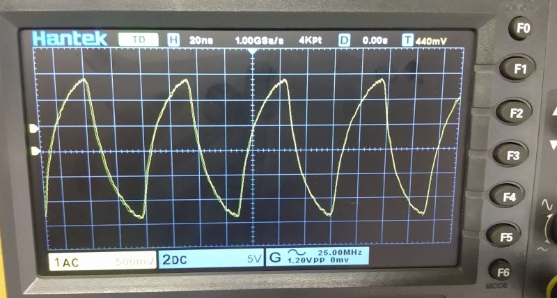
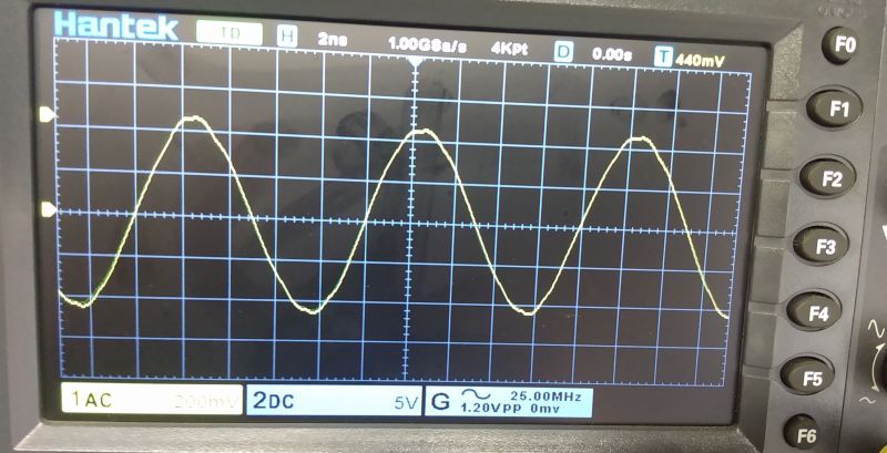
    I just checked on my generator; @ 14MHz ~ 3Vpp for @ 100MHz ~ 450mV. Unfortunately, the soft for Arduino Nano from RS-HFIQ blocks the generator's output for frequencies outside the amateur bands. The shape of the output waveform also changes depending on the frequency. Less than 14MHz;

    UART configurable frequency generator by piotr_go

    I 100MHz;


    UART configurable frequency generator by piotr_go

    The shape of the waveform when used as a VFO in SDR is of secondary importance because the mixer is mostly digital switched analog keys (four signals are phase shifted by 90 °), for a traditional mixer it is good to have a 50? wideband transformer at the output. I checked on a diode mixer (without a broadband transformer) by connecting Si directly to the mixer input I IF. in the factory NFM receiver module and there were no problems.

    @piotr_go and how to connect a digital port expander to I?C (band control) and use the remaining two free pins of the Prock for e.g. TX / RX switching? I see potential in your study :spoko:
  • #10
    _lazor_
    Moderator of Designing
    @ArturAVS SDR requires much better hardware. The mismatched path and lack of termination lead to the oscilloscope measurements to be incorrect (in the sense what you see on the oscilloscope is not the real output of the generator).

    I don't know why you want a broadband transformer, the voltage drop probably doesn't come from the generator itself, but from the line mismatch.
  • #11
    piotr_go
    DIY electronics designer
    ArturAVS wrote:
    as if to join I?C

    Maybe in v2, if it does. It would be better to change the slinger to one that is more accessible.

    Today I found an old damaged kit for a 1.2Ghz meter from the lumber. It must have been lying for 20 years. It's a miracle I didn't dismantle it. :)
    The slingshot was crazy, fortunately the electrode was soft to it, so I uploaded it and started it.
    Unfortunately, the prescaler turned out to be broken too, so I won't be able to find myself.
  • #12
    ArturAVS
    Moderator HP/Truck/Electric
    _lazor_ wrote:
    You need much better-made equipment for SDR.

    No offense to your knowledge, but it doesn't necessarily have to be better equipment (organoleptically tested). After all, Si5351 does not participate directly in the signal processing for SDR but only serves as a controlled "digital" heterodyne. The transformer is useful in analog receivers.

    piotr_go wrote:
    Unfortunately, the prescaler turned out to be broken too, so I won't be able to find myself.

    Of the many Si5351A-based constructions, all of them needed to be calibrated, did you take that into account too?
  • #13
    _lazor_
    Moderator of Designing
    ArturAVS wrote:
    _lazor_ wrote:
    You need much better-made equipment for SDR.

    No offense to your knowledge, but it doesn't necessarily have to be better equipment (organoleptically tested). After all, Si5351 does not participate directly in the signal processing for SDR but only serves as a controlled "digital" heterodyne. The transformer is useful in analog receivers.


    It depends on what modulation (FM, AM, QPSK, QAM?) And I don't mean directly about Si5351 but about PCB design. Because a good scalak is also followed by the need to know how to design a PCB for such a scalak.
    30MHz and a board designed in such a way?

    At the same time, if someone is satisfied with saliva instead of glue, it is cool, I speak from my point of view and experience, and it would not be enough for me.
  • #14
    ArturAVS
    Moderator HP/Truck/Electric
    _lazor_ wrote:
    I don't mean Si5351 directly, but PCB design. Because a good scalak is also followed by the need to know how to design a PCB for such a scalak.
    30MHz and a board designed in such a way?

    You're right here. Piotr made the board as he did, ignoring all the rules for RF, and at least it would fit to output the signals from Si to the SMA sockets through appropriately designed signal paths. Many of the factory Si modules also in terms of PCBs leave a lot to be desired.

    _lazor_ wrote:
    At the same time, if someone is satisfied with saliva instead of glue, it is cool, I speak from my point of view and experience, and it would not be enough for me.

    Not everyone is a perfectionist :D Piotr probably wanted to show how you can easily use Si to replace a generator with an unusual frequency, but I like this minimalist version.
  • #15
    piotr_go
    DIY electronics designer
    ArturAVS wrote:
    Of the many Si5351A-based constructions, all of them needed to be calibrated, did you take that into account too?

    There is (photo from the menu)

    ArturAVS wrote:
    Piotr probably wanted to show how you can easily use Si to replace a generator with an unusual frequency

    Exactly.

    This 112.5MHz is mainly a curiosity so that you can check on the radio if it works.
  • #16
    ArturAVS
    Moderator HP/Truck/Electric
    piotr_go wrote:
    There is (photo from the menu)

    In fact, it somehow escaped my attention :D
  • #17
    _lazor_
    Moderator of Designing
    piotr_go wrote:
    This 112.5MHz is mainly a curiosity so that you can check on the radio if it works.


    It should only be noted that the generator output is low Z (50 ohms) and with impedance mismatch we have cases where RLC or RC filters are formed, so you have to assume that if something does not work, it is not necessarily the radio, but the generator itself.
    From poverty you can simply use adapters and use BNC / SMA on the terminal block, you didn't make long paths, so they probably won't have such a huge impact.
  • #18
    piotr_go
    DIY electronics designer
    _lazor_ wrote:
    From poverty you can simply use BNC / SMA adapters

    I didn't connect it to the radio. I have attached a piece of wire and you can easily pick it up within a dozen or so meters.
  • #19
    _lazor_
    Moderator of Designing
    What do you receive? also a piece of wire?
  • #20
    piotr_go
    DIY electronics designer
    The yellow one in the film. Possibly an antenna that the radio has.
    A simple test. Everyone probably has an FM radio at home, phone or car.
  • #21
    H3nry
    Level 32  
    ArturAVS wrote:
    _lazor_ wrote:
    It would be nice to do a sweep and check how the signal amplitude changes

    I just checked on my generator; @ 14MHz ~ 3Vpp for @ 100MHz ~ 450mV. Unfortunately, the soft for Arduino Nano from RS-HFIQ blocks the generator's output for frequencies outside the amateur bands. The shape of the output waveform also changes depending on the frequency. Less than 14MHz;

    UART configurable frequency generator by piotr_go

    I 100MHz;


    UART configurable frequency generator by piotr_go


    Incorrect measurement result due to mismatch and limited measurement bandwidth of the oscilloscope.
  • #22
    ArturAVS
    Moderator HP/Truck/Electric
    Before you start filing your sentences, you could at least ask about the parameters of the equipment and the measurement conditions. And here I will warn you; oscilloscope analog band 150 MHz (probe Rhode & Schwarz 300MHz calibrated), board of the factory module with Si5351A on board with 50? terminator on the dedicated signal output. Matching or not could result from the PCB topology of the module itself, and on the other hand, Si is rather a digital signal generator with 3V logic and amateurs found its use as a VFO / BFO. Experimenting with it myself, I used one Si as a VFO for the first transformation, VXO for the second and BFO for the SSB detector.
  • #23
    H3nry
    Level 32  
    So I was right, there was no matching of the measuring input and the bandwidth was too small.
  • #25
    ArturAVS
    Moderator HP/Truck/Electric
    _lazor_ wrote:
    It never measures 1: 1. I hope you didn't measure?

    Unfortunately, yes, 1: 1. In a few weeks I will expand this SDR a bit and I will repeat the measurements.
  • #26
    _lazor_
    Moderator of Designing
    You also have an example of how termination works:
    https://tinyurl.com/ye97ohvs

    play with the value of the resistor, signal shape, etc. The fact that there was a sine curve at 14MHz also does not have to be true, if the circuit was badly terminated (I have not seen the PCB schematic, so I do not know if it was well terminated, but I am afraid it was not).
  • #27
    miszcz310
    Level 22  
    I downloaded the software because I was interested in how the menu is written. And here he sneezes, because only binaries. But all in all, I understand that you have to somehow defend yourself against the ubiquitous majfrends.
    Could you describe how it is made? It can also be via PW.
    regards
  • #28
    piotr_go
    DIY electronics designer
    miszcz310 wrote:
    Could you describe how it is done. It can also be via PW.

    A piece of the menu went to PW.