Hello!
I recently came across this board while looking to convert an Aubess/Tuya relay to OpenBeken... And I was wondering what was making my smart lights tchuutchuu! So please join me in this teardown and modding journey

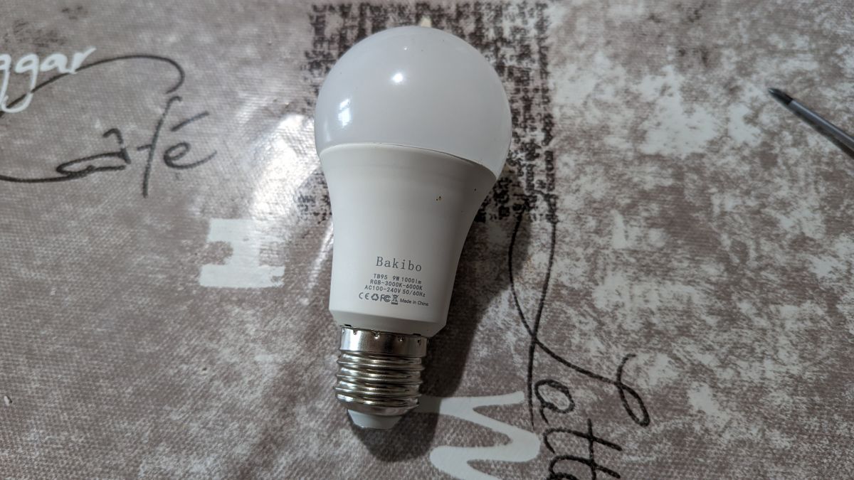
I bought these lights back in 2019 from
Amazon France. They are not available anymore, this link is only for reference. The build quality is good, the body is made of plastic and aluminum. It is compatible with Google Home and Alexa but you need the Smart Life app... Which I'm not a fan of.
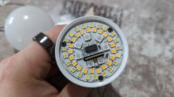
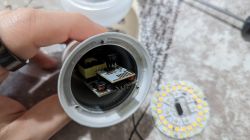
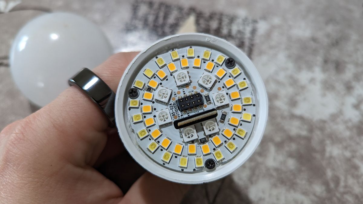
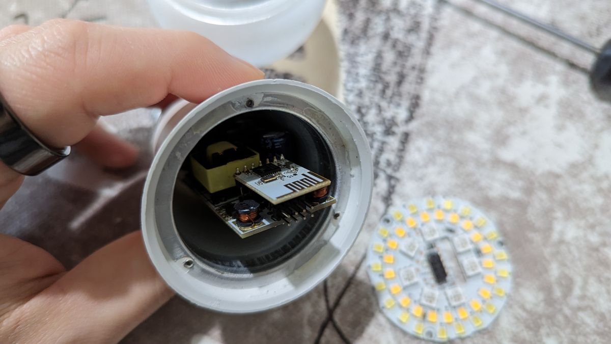
The white dome is held secured to the housing with 2 or 3 dots of glue. Simply twist the dome to break the joints, and unclip it from the housing when it starts rotating. The electronics are made of 3 pieces: the LED board, power supply, and driver board. The LED board is held secured to the housing with 3 small screws and a bit of glue: unscrew the screws then use a dental pick or a small flat screwdriver to pry the board up to break the glue joints. Upon reassembly, I would add some thermal paste where the board meets the housing to help dissipate the heat. The driver board sticks through the LED board... Push against it with your thumb while pulling the LED board to keep the power supply + driver boards inside.

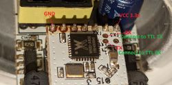
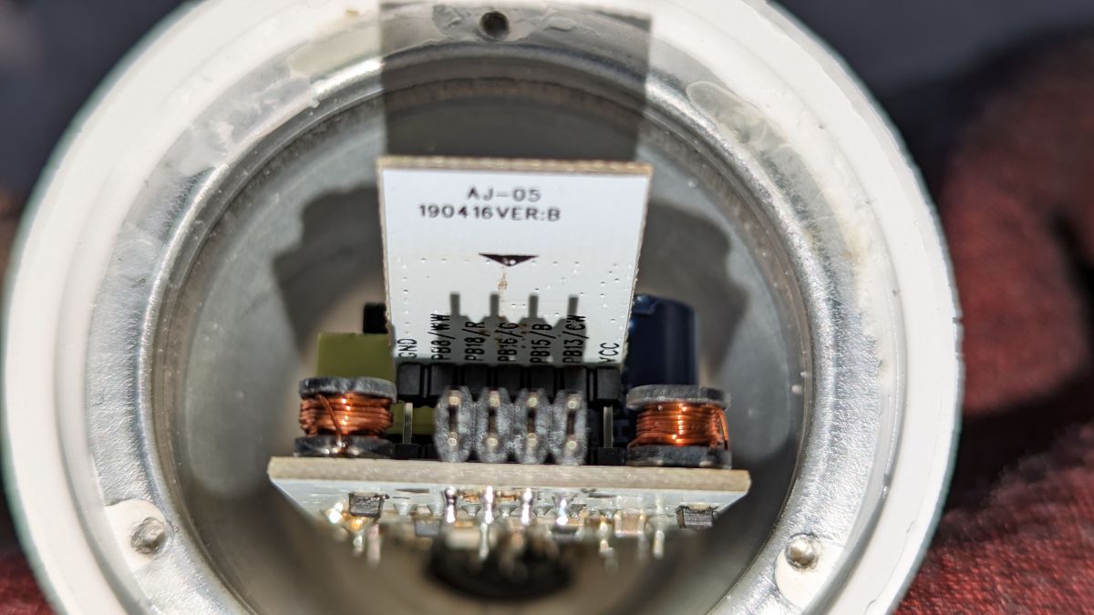
The driver board is soldered to the power supply. By the way, the power supply looks to be a real switching power supply, which is way better than what you can find in an Aubess/Tuya relay! There might be high voltage in there so be careful, but you could connect a USB-TTL converter to the driver board without fearing of frying your USB-TTL or computer. Back to the driver board, it is identified as "AJ-05" on the back, where you can also see the pinout! That's so convenient
(left to right)
- GND
- PB8/WW
- PB18/R
- PB16/G
- PB15/B
- PB13/CW
- VCC (3.3v)
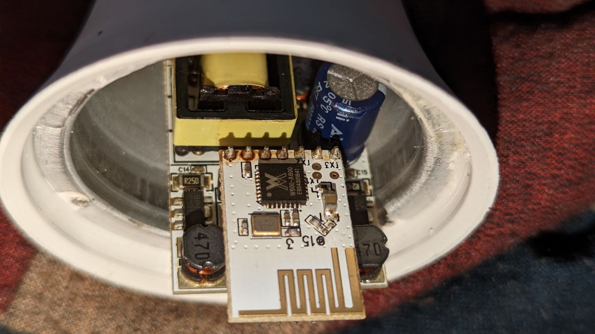
The board hosts a Winnermicro W600-A800 microcontroller
datasheet here.
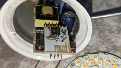

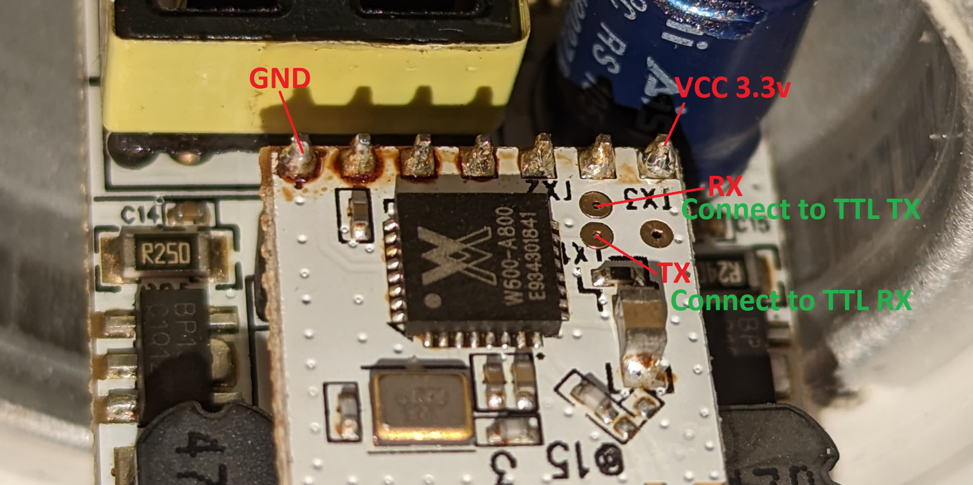
We can see 3 test pads on the driver board next to the W600 chip, this is where it gets interesting
- TX1 = PA4 - UART0_TX
- TX2 = PA5 - UART0_RX
- TX3 = TEST (useless for us)
In other words... Would you want to connect this lamp to a USB-TTL converter this is what you would want to do:
Ok... and now what? Well now we can flash
our favorite OpenBeken app on the chip, and unleash the potential of the light bulb! Well... kind of... more on that later.
I started using
vshymanskyy's w600tool software. Since the reset pin is not readily available on the driver board, we can briefly disconnect then reconnect the ground pin to reset the device when w600tool asks for a reset. Let's say your USB-TTL is known on your computer as COM8, first let's check if we talk the same language as the chip by reading its MAC address:
If the output looks decent, let's continue and flash the chip! At this point, I realized there was
another tool from OpenBK team that could be used to flash the chip and I think that's the one I used... The OpenW600_xxxxx.fls file was downloaded
OpenBK2731T_App releases page on Github, look for the W600 UART flash file.
Reboot the device, and you should see a new Wifi popping up around you called OpenW600something. Connect to it, browse to
http://192.168.4.1 and configure the device to match your wills (wifi, mqtt...). Then, configure the pins:
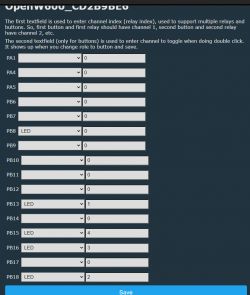
With these settings, each color has its own channel. However, there is an issue: they are not dimmable. They are either on or off. I tried playing with the settings to get some PWM working but I couldn't get any working results. OpenW600 does not even support PWM on all pins... I'm pretty sure the hardware is capable of outputting PWM on those pins because there is no driver down the line toward the LEDs, only humble transistors. So I guess some modifications would be required on the firmware, I'll look into that later.
Anyways! Now the light bulb can be reassembled and updated using the OTA feature of the OpenBK/OpenW600 firmware.


Comments
Thanks for very detailed description. I am suprised that there is a PWM issue, please look into it if you can, you can build obk online, no need to setup compiler on your PC. Otherwise I'll try to look... [Read more]
Thank you. I may have misconfigured the pins tho... In such a case, I guess setting the pin to PWM should work, correct? I already have the code and the compiler on my computer because I also highly modified... [Read more]
I've been thinking about that temperature issue and I assumed the simplest way to handle it without codebase changes would be to do addChangeHandler with publishFloat command and multiple there value by... [Read more]
Follow-up: OTA was broken, even when compiling the firmware locally. It was partially working since I could not even start another OTA from the web app after trying and failing one first time. Something... [Read more]
We've really tried to reduce the OTA image size so it works again. Problem should be solved, at least for the time being. HTTPS support would take too much memory, we can't afford that on W600 platform,... [Read more]
I have a TW-03 based device (MLB7-1025-WHT, https://monsterilluminessence.com/product/smart-led-light-strip/ ) with PWM configures on PB15/PB16/PB18 and I'm also having the issue where PWM doesn't work.... [Read more]
The link you have posted is giving me "403 Forbidden", even with extra brace character removed from the end. Maybe it's not available from EU? I can try to look into that PWM issue soon, in a meantime,... [Read more]
I have a similar issue with the same setup. RGB LED on pins 15, 16, 18 on the TW-03 chip. Running version 1.17.291. if I set pins to relay I can turn LEDs on and off, but if set to PWM the LEDs stay... [Read more]
I haven't seen this issue yet, but maybe we should turn off totally PWM in HAL when a 0 duty is passed: https://github.com/openshwprojects/OpenBK7231T_App/blob/main/src/hal/w800/hal_pins_w800.c [Read more]
I think that may work. I'm willing to give it a test, but am not well versed in compiling binaries. [Read more]
If you open a pull request, you get automatic online builds for all supported platforms. [Read more]